1
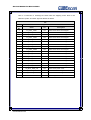
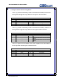
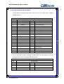
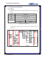
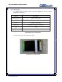
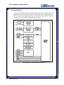
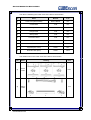
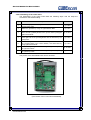
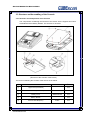
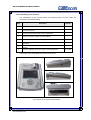
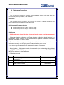
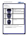
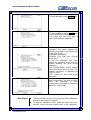
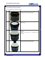
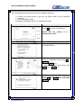
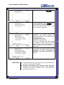
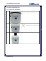
Service Manual
Service Manual for BioCon-500TM
CUBEscan BioCon-500 Service Manual
The Information contained in this service manual is proprietary to the Mcube Technology
Co., Ltd. It is only used for convenience of our customers. It may not be changed in whole
or in part without the written notice.
Any service work performed by persons who are not authorized by Mcube Technology Co.,
Ltd. may void your warranty.
This service manual contains technical contents for service as below.
-
Product configuration
Product configuration and block diagram
Product components and their functions
Signal interface and their definition
-
Structure and assembling of the device
Structure and components
Assembling sequence
-
Signal test
-
Troubleshooting
Mcube Technology Co., Ltd.
www.mcubetech.co.kr
i
Service Manual for BioCon-500TM
Table of Contents
Contents
1. Product Configuration
Page
---------
1
1.1 Maintenance Mode Password
---------
1
1.2 Product Configuration
---------
2
1.3 Signal Interface
---------
4
1.3.1 Signal Interface of the Control Board
---------
5
1.3.2 Signal Interface of the Analog Board
---------
11
1.3.3 Signal Interface of the Key Board
---------
13
1.3.4 Signal Interface of the Charge Board
---------
14
1.3.5 Signal Interface of the Battery Board
---------
15
---------
16
2.1 DC Adapter
---------
16
2.2 Ultrasonic Probe
---------
17
2.3 Battery Module
---------
17
2.4 LCD Module
---------
18
2.5 Printer Module
---------
19
2.6 Charge Board
---------
19
2.7 Analog Board
---------
20
2.8 Control Board
---------
22
---------
24
---------
24
3.1.1. Structure and Components of the Upper Case
---------
24
3.1.2. Assembling of the Upper Case
---------
26
---------
27
---------
27
2. The Components of the Product
3. Structure and Assembling of the Device
3.1. Structure and Assembling of the Upper Case
3.2. Structure and Assembling of the Lower Case
3.2.1. Structure and Components of the Lower Case
Mcube Technology Co., Ltd.
www.mcubetech.co.kr
ii
Service Manual for BioCon-500TM
3.2.2. Assembling of the Lower Case
---------
29
---------
30
3.3.1. Structure and Components of the Console
---------
30
3.3.2. Assembling of the Console
---------
31
---------
32
---------
32
---------
33
---------
34
4.1. DC Adapter Cable
---------
34
4.2. Ultrasonic Probe Cable
---------
35
4.3. USB Cable
---------
36
---------
37
---------
37
5.1.1. Power Test
---------
37
5.1.2. TCG1 Test
---------
38
5.1.3. TCG2 Test
---------
39
5.1.4. Ultrasonic Pulse Test
---------
40
5.2. Test for the Control Board
---------
41
5.2.1. Power Test
---------
41
5.2.2. LCD Test
---------
41
6. Troubleshooting
---------
46
7. Maintenance Mode
---------
50
8. Calibration Procedures
---------
54
8.1 Purpose
---------
54
8.2 Scope
---------
54
8.3 Supported Firmware Version
---------
54
3.3. Structure and Assembling of the Console
3.4. Structure and Assembling of the Ultrasonic Probe
Module
3.4.1. Structure and Components of the Ultrasonic
Probe Module
3.4.2. Assembling of the Ultrasonic Probe Module
4. External Cable Configuration
5. Signal Test
5.1. Test for Analog board
Mcube Technology Co., Ltd.
www.mcubetech.co.kr
iii
Service Manual for BioCon-500TM
8.4 General
---------
54
8.5 Procedures
---------
55
8.5.1 Calkit calibration
---------
55
8.5.2 CubeScan Phantom Calibration
---------
59
8.5.3 Dansk Phantom Calibration
---------
61
---------
65
8.6 Error Messages during CaliKit Calibration and
CubeScan Phantom Calibration
Mcube Technology Co., Ltd.
www.mcubetech.co.kr
iv
Service Manual for BioCon-500TM
1. Product Configuration
1.1
Maintenance Mode Password
BioCon-500 has two system modes. One is Normal mode, and the other is
Maintenance mode. Normal mode is for the normal user, and Maintenance mode is for
the technicians in the hospital or service engineers. To enter the maintenance mode,
push LEFT key with ENTER key being pushed and then push PRINT key after the
system is turned on and the top screen is displayed in normal mode. When you press
‘ENTER+LEFT+PRINT’ keys, the BioCon-500 asks for the Maintenance mode
password (after the firmware version 3.1.009). Input ‘1122’ for the password. You
cannot change the password.
Mcube Technology Co., Ltd.
www.mcubetech.co.kr
1
Service Manual for BioCon-500TM
1.2
Product Configuration
BioCon-500
TM
is a 3-dimensional ultrasonic equipment to measure the bladder volume
and quantity of remaining urine safely and comfortably through non-invasive method. Its
overall structure is as below.
(System Configuration of BioCon-500)
Mcube Technology Co., Ltd.
www.mcubetech.co.kr
2
Service Manual for BioCon-500TM
The system, in large, consists of a console, an ultrasonic probe, and a DC adapter
Component
DC Adapter
Console
Ultrasonic Probe
Function
Supplies a DC power required in the Charge Board for charging
at the system.
Controls system operation and various signals, and handles
signal transmission and reception.
Transmits and receives the ultrasonic signals, being used in close
contact with the patient.
The Console consists of a printer module, a LCD module, a battery module, and a
number of boards. Its functions are as below.
Component
Function
Charge Board
Charges the battery module with DC 16V input from a DC
adapter.
Battery Board
Connects the Charge Board and the Battery Module.
Transmits an ultrasonic pulse to the ultrasonic probe, processes
Analog Board
the signal just received, and transmits the data transferred
through the A/D converter to the control board. It also drives the
stepping motors required in imaging.
Connection Board
Key Board
Input from a user.
Performs interfacing between the users and the system.
Controls the overall system with following major functions.
- Processes user’s input.
- Drives the stepping motor of the thermal printer and
transmits data
Control Board
- Controls the charging of a battery module
- Interfaces PC through USB.
- Displays data on LCD
- Processes data received from the Analog Board
Battery Module
LCD Module
Printer Module
Provides the power required in the system.
Displays various information.
Prints the information about the bladder and bladder images on
the thermal paper
Mcube Technology Co., Ltd.
www.mcubetech.co.kr
3
Service Manual for BioCon-500TM
1.3 Signal Interface
The signal interface for the system is as below.
DC Adapter
J1
J2
Charging
Board
J7
JP101
J5
JP2
J4
JP1
Battery
Board
J1
Battery
Module
Printer
Module
JP2
JP6
JP1
JP7
J6
J2
Analog Board
JP3
JP7
JP4
JP5
JP6
JP4
JP5
Ultrasonic
Probe
Connection
Board
JP1
JP2
JP3
JP1
JP2
JP3
PC
J4
USB
Control
Board
J2
Key Board
J1
J3
JP5
JP4
LCD Module
(Structure of Signal Interface at BioCon-500)
Mcube Technology Co., Ltd.
www.mcubetech.co.kr
4
Service Manual for BioCon-500TM
1.3.1 Signal Interface of the Control Board
JP1 is a connector to exchange the data with ADC (Analog-Digital Converter) in the
Analog Board. And each signal is defined as below.
JP1
TO:
Analog Board Connection
Pin No.
Name
I/O
1
FH_DB0
In
AD Conversion Data In bit 0
2
FH_DB1
In
AD Conversion Data In bit 1
3
FH_DB2
In
AD Conversion Data In bit 2
4
FH_DB3
In
AD Conversion Data In bit 3
5
FH_DB4
In
AD Conversion Data In bit 4
6
FH_DB5
In
AD Conversion Data In bit 5
7
FH_DB6
In
AD Conversion Data In bit 6
8
FH_DB7
In
AD Conversion Data In bit 7
9
FH_DB8
In
AD Conversion Data In bit 8
10
FH_DB9
In
AD Conversion Data In bit 9
11
FH_DB10
In
AD Conversion Data In bit 10
12
FH_DB11
In
AD Conversion Data In bit 11
13
FH_BLANK
Out
Blank signal
14
FH_AD_CS
Out
ADC chip select
15
FH_AD_RD
Out
ADC Read
16
FH_CONVST
Out
ADC Conversion Start
17
FH_AD_CLK
Out
ADC clock
18
FH_AD_BUSY
In
ADC busy
19
FH_POS_PULSE
Out
To generate positive pulse
20
PH_NEG_PULSE
Out
To generate negative pulse
Mcube Technology Co., Ltd.
www.mcubetech.co.kr
Description
5
Service Manual for BioCon-500TM
JP2 is a connector representing a power from the analog board and other various
signals. And each signal is defined as belows.
JP2
To:
Analog Board Connection
Pin
No.
Name
I/O
1
H_BAT_UNSWITCHED
Power
Input power from analog board
2
H_BAT_UNSWITCHED
Power
Input power from analog board
3
H_BAT_UNSWITCHED
Power
Input power from analog board
4
H_BAT_UNSWITCHED
Power
Input power from analog board
5
SWITCHING_ON
Out
To say that control board is on.
6
-
-
Reserved
7
-
-
Reserved
8
-
-
Reserved
9
-
-
Reserved
10
-
-
Reserved
11
-
-
Reserved
12
-
-
Reserved
13
VDD
Power
ADC digital logic power
14
VDD
Power
ADC digital logic power
15
Ground
Power
Ground signal
16
Ground
Power
Ground signal
17
Ground
Power
Ground signal
18
CH_AN_PWR_ON
Out
19
CH_SCLK
in
Probe detection signal
20
FH_SCAN_SW
In
Probe scan switch input
Mcube Technology Co., Ltd.
www.mcubetech.co.kr
Description
Analog board power on/off
6
Service Manual for BioCon-500TM
JP3 is a connector to exchange the data with the stepping motor built in the
ultrasonic probe. And each signal is defined as below.
JP3
To:
Analog Board Connection
Pin
No.
Name
I/O
1
FH_MOT_CON1
Out
Probe motor driver control signal
2
FH_MOT_CON2
Out
Probe motor driver control signal
3
FH_MOT_CON3
Out
Probe motor driver control signal
4
FH_MOT_CON4
Out
Probe motor driver control signal
5
FH_MOT_CON5
Out
Probe motor driver control signal
6
FH_MOT_CON6
Out
Probe motor driver control signal
7
FH_MOT_CON7
Out
Probe motor driver control signal
8
FH_MOT_CON8
Out
Probe motor driver control signal
9
FH_MOT_CON9
Out
Probe motor driver control signal
10
FH_MOT_CON10
Out
Probe motor driver control signal
11
FH_MOT_CON11
Out
Probe motor driver control signal
12
FH_MOT_CON12
Out
Probe motor driver control signal
13
FH_MOT_CON13
Out
Probe motor driver control signal
14
FH_MOT_CON14
Out
Probe motor driver control signal
15
FH_MOT_CON15
Out
Probe motor driver control signal
16
FH_MOT_CON16
Out
Probe motor driver control signal
17
CH_MOT_PWR_ON
Out
Probe motor power on/off
18
H_PROBE_PWR
Power
Power for motor driving
19
H_PROBE_PWR
Power
Power for motor driving
20
Ground
Power
Ground signal
Mcube Technology Co., Ltd.
www.mcubetech.co.kr
Description
7
Service Manual for BioCon-500TM
JP4 is a connector to provide a driving power required in LCD backlight. And each
signal is defined as below.
JP4
TO:
LCD Backlight
Pin No.
Name
I/O
Description
1
High
Out
2
-
-
Not used
3
-
-
Not used
4
Low
Out
AC high voltage
Ground
JP5 is a connector related to an LCD display and connected to an LCD module.
And each signal is defined as below.
JP5
TO:
LCD Module
Pin No.
Name
I/O
Description
1
VD0
Out
Display data signal
2
VD1
Out
Display data signal
3
VD2
Out
Display data signal
4
VD3
Out
Display data signal
5
VM
Out
Display on/off signal
6
VFRAME
Out
Scan start-up signal
7
-
-
8
VLINE
Out
Data input latch signal
9
VCLK
Out
Data input clock signal
10
VCC
Power
Power supply for logic(+5V)
11
Ground
Power
Ground signal
12
VEE
Power
Power supply for LCD
13
VO
Power
LCD contrast adjust voltage
14
Ground
Power
Ground signal
Mcube Technology Co., Ltd.
www.mcubetech.co.kr
Not used
8
Service Manual for BioCon-500TM
JP6 and JP7, the connector terminals for the connection with the printer module, are
connectors for the driving of a stepping motor built in the printer module, for data latch,
for data I/O, and for power. And each signal is defined as below
JP6
TO:
Printer Module
Pin No.
Name
I/O
Description
1
FP_STROBE3
Out
Third strobe
2
FP_STROBE2
Out
Second strobe
3
FP_STROBE1
Out
First strobe
4
VP_LOGIC
Power
5
FP_PRI_CLK
Out
Serial clock
6
FP_LATCH
Out
Latch
7
FP_PRI_DATA_IN
IN
8
PRT_PWR
Power
Dot-line voltage
9
PRT_PWR
Power
Dot-line voltage
10
SM4
Out
Fourth phase of stepper motor
11
SM3
Out
Third phase of stepper motor
12
SM2
Out
Second phase of stepper motor
13
SM1
Out
First phase of stepper motor
Logic voltage
Data input
JP7
TO:
Printer Module
Pin No.
Name
1
CO
Collector of photo-transistor
2
VF
Anode of photo-sensor
3
L-GND
Power
Ground for logic
4
PRT_PWR
Power
Dot-line voltage
5
PRT_PWR
Power
Dot-line voltage
6
FP_PRI_DATA_OUT
Out
Data output
7
FP_STROBE6
Out
Sixth strobe
8
FP_STROBE5
Out
Fifth strobe
9
FP_STROBE4
Out
Fourth strobe
10
P-GND
Power
Ground for dot-line
11
P-GND
Power
Ground for dot-line
12
P-GND
Power
Ground for dot-line
13
P-GND
Power
Ground for dot-line
14
TM
In
Mcube Technology Co., Ltd.
www.mcubetech.co.kr
I/O
Description
Thermistor first terminal
(second is ground)
9
Service Manual for BioCon-500TM
J3 is a connector for the connection with the Key Board, a user input device. And
each signal is defined as below.
J3
TO:
Key Board
Pin No.
Name
I/O
Description
1
POW_OUT
Out
For turn on/off power
2
POW_IN
In
For turn on/off power
3
-
-
Not used
4
-
-
Not used
5
SW1
In
Print key input
6
SW2
In
Scan key input
7
SW3
In
Up key input
8
SW4
In
Down key input
9
SW5
In
Right key input
10
SW6
In
Left key input
11
SW7
In
Enter key input
12
SW8
In
Power key input
13
-
-
Not used
14
-
-
Not used
15
VDD
Power
16
CK_LIGHT
In
Reserved
17
-
-
Not used
18
-
-
Not used
19
Ground
Power
Ground signal
20
Ground
Power
Ground signal
"+3.3V"
J4 is a connector for data exchange between PC and BioCon-500 through USB.
The USB cable is the type-B. And each signal is defined as below.
J4
TO:
USB Interface
Pin No.
Name
I/O
1
VUSB
In
+5V input from PC
2
D+
I/O
USB D+ line
3
D-
I/O
USB D- line
4
Ground
Power
Mcube Technology Co., Ltd.
www.mcubetech.co.kr
Description
Ground signal
10
Service Manual for BioCon-500TM
1.3.2 Signal interface of the Analog Board
JP1 is a (+) terminal of the battery module connected from the battery module to the
analog board through the Charge Board. And its signal is defined as below.
JP1
TO:
Charge Board
Pin No.
Name
I/O
Description
1
BAT_POS
Power
Input power from charge board
2
BAT_POS
Power
Input power from charge board
JP2 is a (-) terminal of the battery module connected from the battery module to the
analog board through the Charge Board. And the signal is defined as below.
JP2
TO:
Pin No.
Charge Board
Name
I/O
1
BAT_NEG
Power
2
BAT_NEG
Power
Description
Ground for input power from the Charge
Board
Ground for input power from the Charge
Board
JP101 is a signal to control ON/OFF of DC power supplied from the DC adapter to
the Charge Board. And its signal is defined as below.
JP101
TO:
Charge Board
Pin No.
Name
I/O
Description
1
ANP_PWR_ON
Out
Analog board power on/off
2
EE+5V
Power
Mcube Technology Co., Ltd.
www.mcubetech.co.kr
"+5V"
11
Service Manual for BioCon-500TM
JP3 is a connector linked to the ultrasonic probe. And it consists of signals for a
driving of a stepping motor built in the ultrasonic probe, a signal for transmission and
reception of the electric signals with ultrasonic oscillator, and a signal for reception of
the input from the switch built in the ultrasonic probe. These signals are defined as
below.
JP3
TO:
Ultrasonic Probe
Pin No.
Name
I/O
1
Shield ground
Power
Description
Cable shield
2
CHECK_CON2
in
Check Connector 2(Orange)
3
SCAN_SW & DATA
In
Scan switch input from probe (Grey)
4
-
-
Not Connected
5
ANGLE1
Out
6
CHECK_CON2
7
-
8
in
Step motor control signal (Red)
Check Connector 2 (Violet)
-
Not Connected
ANGLE2
Out
Step motor control signal (Blue)
9
-
-
10
ANGLE3
Out
Step motor control signal (White)
11
ANGLE4
Out
Step motor control signal (Black)
12
-
-
13
PLANE1
Out
Not Connected
Not Connected
Step motor control signal (Brown)
14
-
-
15
PLANE2
Out
Not Connected
Step motor control signal (Green)
16
PLANE3
Out
Step motor control signal (Pink)
17
PLANE4
Out
Step motor control signal (Yellow)
18
SIGNAL
I/O
Signal line (Coaxial +)
19
-
-
20
SIG_GND
Power
Not Connected
Signal ground (Coaxial Shield)
*. JP7, JP4, JP5: Refer to JP1, JP2, and JP3 of Control Board, respectively.
Mcube Technology Co., Ltd.
www.mcubetech.co.kr
12
Service Manual for BioCon-500TM
1.3.3 Signal Interface of the Key Board
J1 is a signal to deliver the key input from the user to the control board. And it is
defined as below.
J1
TO:
Control Board
Pin No.
Name
I/O
Description
1
POW_OUT
In
For turn on/off power
2
POW_IN
Out
For turn on/off power
3
-
-
Not Connected
4
-
-
Not Connected
5
SW1
Out
Print key output
6
SW2
Out
Scan key output
7
SW3
Out
Up key output
8
SW4
Out
Down key output
9
SW5
Out
Right key output
10
SW6
Out
Left key output
11
SW7
Out
Enter key output
12
SW8
Out
Power key output
13
-
-
Not Connected
Not Connected
14
-
-
15
VDD
Power
16
-
-
Not Connected
17
-
-
Not Connected
"+3.3V"
18
-
-
Not Connected
19
Ground
Power
Ground signal
20
SIG_GND
Power
Signal ground (Coaxial Shield)
J2 is a connector for LEDs to display the status both of the DC adapter connection
and of charging. And each signal is defined as below.
J2
TO:
Charge Board
Pin No.
Name
I/O
1
ADAPTER_ON_ANODE
In
Adapter on LED anode
2
ADAPTER_ON_CATHODE
In
Adapter on LED cathode
3
FAST_CHARGE_ANODE
In
Fast charge LED anode
4
FAST_CHARGE_CATHODE
In
Fast charge LED cathode
Mcube Technology Co., Ltd.
www.mcubetech.co.kr
Description
13
Service Manual for BioCon-500TM
1.3.4 Signal Interface of the Charge Board
J1 is a power input from DC adapter. And it is defined as below.
J1
TO:
DC Adapter
Pin No.
Name
I/O
Description
1
ADAPTER+
Power
+16V input
2
ADAPTER-
Power
Ground
3
-
-
Not Connected
J2 is a connector for LEDs to display the status both of the DC adapter connection and
of charging. And each signal is defined as below.
J2
TO:
Key Board
Pin No.
Name
I/O
Description
1
ADAPTER_ON_ANODE
Out
Adapter on LED anode
2
ADAPTER_ON_CATHODE
Out
Adapter on LED cathode
3
FAST_CHARGE_ANODE
Out
Fast charge anode
4
FAST_CHARGE_CATHODE
Out
Fast charge cathode
J6 is a connector connected to (+) and (-) terminals of the battery board. And each
signal is defined as below.
J6
TO:
Battery Board
Pin No.
Name
I/O
Description
1
BATTERY+
Power
Battery module plus
2
BATTERY-
Power
Battery module minus
3
-
-
Reserved
*. J7, J4, J5: Refer to JP101, JP1, and JP2 of Analog Board, respectively.
Mcube Technology Co., Ltd.
www.mcubetech.co.kr
14
Service Manual for BioCon-500TM
1.3.5 Signal Interface of the Battery Board
J1 is a connector connected to (+) and (-) terminals of the battery module. And it is
defined as below.
J1
TO:
Battery Module
Pin No.
Name
I/O
Description
1
BATTERY-
Power
2
-
-
Reserved
3
-
-
Reserved
4
-
-
Reserved
5
BATTERY+
Power
Battery module minus
Battery module plus
J2 is a connector connected to (+) and (-) terminals of the battery board. And it is
defined as below.
J2
TO:
Battery Board
Pin No.
Name
I/O
1
BATTERY-
Power
2
-
-
Reserved
3
-
-
Reserved
4
-
-
Reserved
5
BATTERY+
Power
Mcube Technology Co., Ltd.
www.mcubetech.co.kr
Description
Battery module minus
Battery module plus
15
Service Manual for BioCon-500TM
2. The Component of the Product
2.1 DC Adapter
Supplies the DC power required in charging the battery module. And its specification
is as below.
Section
Specification
Input
100 ~ 240V, 50~60Hz, 1.2A
Output
+16V, 2.8A
Inner part
Positive
Outer part
Negative
DC Plug
(Specification of DC Adapter)
The power system supplied through DC adapter has the following connection
configuration.
(Connection Configuration of Power Signal in BioCon-500)
Mcube Technology Co., Ltd.
www.mcubetech.co.kr
16
Service Manual for BioCon-500TM
2.2 Ultrasonic Probe
Transmits the ultrasonic pulse in close contacts with the patient’s bladder and sends
the received signals reflected from the human body to the analog board band.
Ultrasonic probe consists of a transducer assembly, two motors used in adjusting
the location of a transducer assembly, and a switch board for receiving the scan
start input from the user. The product specification is as below.
Section
Specification
Output Power
1mW maximum
The Working Frequency
2.8MHz
5.85mm (H)
6dB beam area
4.99mm (V)
2
The maximum value of the temporal average
0.0313 mW/cm
Transducer Dimension
14mm diameter
(Specification of the Ultrasonic Probe)
2.3 Battery Module
Is a power source to supply the power to the system. And its specification is as
below.
Section
Specification
Configuration
2S+2P
Voltage
7.4V
Operating
Standard Charge
0 to 45°
C
Temperature
Standard Discharge
-10 to 50°
C
(Specification of the Battery Module)
Mcube Technology Co., Ltd.
www.mcubetech.co.kr
17
Service Manual for BioCon-500TM
2.4 LCD Module
Is a display device to display various information adjusted by the user. And its
specification is as below.
Section
Specification
Display Resolution
320(W) x 240(H) (dots)
Dot Size
0.33(W) x 0.33(H) (mm)
Dot Pitch
0.36(W) x 0.36(H) (mm)
Display Type
FSTN (Black and White), Transmissive
Duty
1/240
Backlight
CCFT inverter
(Specification of the LCD Module)
The actual picture of LCD module is as below.
(Actual Picture of LCD Module)
Mcube Technology Co., Ltd.
www.mcubetech.co.kr
18
Service Manual for BioCon-500TM
2.5 Printer Module
A thermal printer to print out visualized bladder information and visual images. And its
specification is as below.
Section
Specification
Printing Method
thermal dot line printing
Resolution
8 dots/mm
Dot per line
384 dots
Printing Width
48 mm
Paper width
57.5 ± 0.5 mm
(Specification of Printer Module)
2.6 Charge Board
It charges the battery module with the DC power input from DC power adapter.
The configuration of the Charge Board is as below.
Section
Specification
Max charging current
1000 mA
Max charging voltage
8.4 ± 0.05 V
Fault
Red
Full charge
Yellow
LED Display
(Specification of Charge Board)
Mcube Technology Co., Ltd.
www.mcubetech.co.kr
19
Service Manual for BioCon-500TM
2.7 Analog Board
It transmits the ultrasonic pulse to ultrasonic probe, performs the signal process of
signals received by the ultrasonic probe, and sends the data converted through the
A/D converter to the control board. Also, it drives the stepping motor required in
scanning. The block diagram of Analog board is as below.
(Block Diagram of Analog Board in BioCon-500)
Mcube Technology Co., Ltd.
www.mcubetech.co.kr
20
Service Manual for BioCon-500TM
Each block of Analog board has following function.
Classification
Power Control Block
Motor Control Block
Function
Controls ON/OFF of power required in analog board and
supplies the power required in each component.
A motor-driving module for the ultrasonic probe.
A module that generates the pulse required in the ultrasonic
Transceiver
wave generation and receives the ultrasonic reflection
signal from the ultrasonic probe.
TCG
BPF
Main Amp.
Rectifier
ADC
Mcube Technology Co., Ltd.
www.mcubetech.co.kr
TCG (Time Controlled Gain) block to impose Internal timevaried gain.
A band pass filter module to remove the undesired
frequency signal other than the required signal.
A main amplifier module to impose overall gain to the
signal.
Rectifies the signal before A/D conversion.
Transmits the data to the control board by converting
analog into digital.
21
Service Manual for BioCon-500TM
2.8 Control Board
The control board is in charge of the signal for overall system and other various
signals. And its configuration is as below.
) 3 B/ $ 7&+
) 3 B3 5 ,B&/ .
) 3 B3 5 ,B' $ 7$ B,1
-3
) 3 B3 5 ,B' $ 7$ B2 8 7
@
@
) 3B675 2 %( >
&3 B9 / 2 * ,&B2 1
&3 B+ ( $ ' B7( 0 3
&3B35 7B3 : 5 B2 1
&3 B3 $ 3 ( 5 B( 0 3 7<
@
90
-3
3 5 ,1 7( 5
,1 7( 5 ) $ &( %/ 2 &.
9' >
' ,6 3 / $ <B2 1
9 &/ .
&/ B/ &' B$ ' -
&/ B/ &' B&75 /
9 / ,1 (
/ &'
,QW
HUIDFH%ORFN
-3
) 3 B0 2 7B&2 1 >
-3
$
' $ 7 $ >@
$ >@
Q* &6
-
86%
,1 7 ( 5 ) $ &(
%/ 2 &.
' $ 7 $ >@
$' ' 5
Q* &6
( ; 7,1 7
&) B( ; 7,1 7
Q: (
&) BQ; ' 5 ( 4
Q2 (
&) BQ; ' $ &.
&) B72 8 7
&8 B6 8 6 3 ( 1 '
&) B&2 1 ) B&6
&) B&2 1 ) B3 * 0
) 3* $
&) B&2 1 ) B&/ .
&38
&) B&2 1 ) B,1 ,7
&) B&2 1 ) B' ,1
&) B&2 1 ) B' 2 1 (
32: ( 5
%/ 2 &.
&) B6 : B7,0 ( 5
&/ . 2 8 7
&) B72 8 7
-3
-3
Q* &6
Q* &6
Q* &6
Q: %(
Q: %(
Q2 (
Q: (
' $ 7$ >
$>
@
@
-3
0 ( 0 2 5 < %/ 2 &.
(Block Diagram of Control Board in BioCon-500)
Mcube Technology Co., Ltd.
www.mcubetech.co.kr
22
Service Manual for BioCon-500TM
The function of each module in the control board is as below.
Classification
Power Block
Function
Supplies various powers required in control board.
Provides USB interface with PC and supports USB 1.1 full speed.
The connector type is standard USB B type.
USB Interface Block
<Picture of USB cable>
The memory block has a control S/W and a booting S/W and it
includes RAM memory required in driving the control S/W.
Referenc
e NO.
Memory Block
Capacity
Type
Purpose
U1
8M bits
SRAM
RAM section
U2
8M bits
Flash ROM
Control device
U3
8M bits
Flash ROM
Store scan data &
Booting
system information
(Configuration of memory)
A module performing such functions as chattering removal for key
FPGA
input by the user, serial data transmission to the thermal printer,
motor control logic, and memory decoder.
LCD Interface Block
Printer Interface
Block
Provides interface with LCD.
A module to drive motor of thermal printer.
Mcube Technology Co., Ltd.
www.mcubetech.co.kr
23
Service Manual for BioCon-500TM
3. Structure and Assembling of the Device
3.1 Structure and Assembling of the Upper Case
3.1.1 Structure and Components of the Upper Case
The main components constituting the Upper Case of the device are the Printer
Module, the LCD Module and the Key Board. The structure is as below.
(Structure of the Upper Case of the Device)
The items included in the upper case of the device are as below.
No.
Name
Material
Q’TY
①
Upper Case (disassembled)
PC/ABS
1EA
②
Printer Module
1EA
③
LCD Module
1EA
④
Key Board
PCB
1EA
⑤
Direction Button (gray)
SILICONE
1EA
⑥
PWR Button (red)
SILICONE
1EA
⑦
PRINT/SCAN Button (blue)
SILICONE
2EA
⑧
LCD Window
PC 2.5T
1EA
⑨
M3 washer Bolt (6mm)
STEEL
4EA
⑩
M4 screw Bolt (10mm)
STEEL
6EA
Mcube Technology Co., Ltd.
www.mcubetech.co.kr
24
Service Manual for BioCon-500TM
The cables used in the upper case of the device are as below.
No.
Name
⑪
Printer
Cable
1SET
⑫
Key Board
Cable
1EA
⑬
LED
Cable
1EA
⑭
LCD GND
Cable
2EA
⑮
Key Board
GND
Cable
2EA
Mcube Technology Co., Ltd.
www.mcubetech.co.kr
Drawing
Q’TY
25
Service Manual for BioCon-500TM
3.1.2 Assembling of the Upper Case
The assembling of the upper board takes the following steps, and the steps are
reversed for the dissembling.
Step
1
2
3
Description
Remark
Attach the ⑤Direction Button, the ⑥PWR button, and the ⑦
PRINT/SCAN Button to the ④Key Board.
Attach the ④Key Board assembled in step 1 to the rear lower of
the ①Upper Case by using the ⑩M3 washer bolts.
Attach the ③LCD Module to the rear center of the ①Upper
Case by using the ⑨M3 washer bolts.
Insert the ②PRINT Module to the grooves of front upper, then
attach it by using lever lock as below
⑧ X 6EA
⑨ X 4EA
4
5
6
7
Remove the adhesive paper from the rear of the ⑧LCD Window,
then attach in the front center of the ①Upper Case.
Connect the ③LCD Module and the ④Key Board by using the
⑭LCD GND Cables and the fixing holes of them.
Connect the ⑮Key Board GND Cable to the fixing holes in lower
of the ④Key Board.
⑭ X 2EA
⑮ X 2EA
8
Connect the ⑪Printer Cable to the ②PRINT Module.
⑪ X 1SET
9
Connect the ⑫Key Board Cable to the ④Key Board.
⑫ X 1EA
10
Connect the ⑬LED Cable to the ④Key Board.
⑬ X 1EA
The picture of the Upper Case assembled is as below.
(The Picture of the Upper Case Assembled)
Mcube Technology Co., Ltd.
www.mcubetech.co.kr
26
Service Manual for BioCon-500TM
3.2 Structure and Assembling of the Lower Case
3.2.1 Structure and Components of the Lower Case
The main components constituting the Lower Case of the device are the Control
Board, the Analog Board, the Charge Board, and the Battery Board.
The structure is as below.
(Structure of the Lower Case of the Device)
Mcube Technology Co., Ltd.
www.mcubetech.co.kr
27
Service Manual for BioCon-500TM
The items constituting the Lower Case of the device are as below.
No.
Name
Material
Q’TY
①
Lower Case (disassembled)
SHEET METAL
1EA
②
Control Board
PCB
1EA
③
Analog Board
PCB
1EA
④
Charge Board
PCB
1EA
⑤
Battery Board
PCB
1EA
⑥
Connection Board
PCB
1EA
⑦
Spacer
SILICONE
4EA
⑧
Handle
Plastic
1EA
⑨
Supporter (M3, 12mm)
STEEL
2EA
⑩
M3 Washer Bolt (6mm)
STEEL
20EA
The cables used in the Lower Case of the device are as below.
No.
Name
⑪
Power
Cable
1SET
⑫
Battery
Cable
1EA
Mcube Technology Co., Ltd.
www.mcubetech.co.kr
Drawing
Q’TY
28
Service Manual for BioCon-500TM
3.2.2 Assembling of the Lower Case
The assembling of the Lower Case takes the following steps. And the steps are
reversed for the disassembling.
Step
Description
Remark
1
Attach the ⑦Spacers to the ①Lower Case with 10mm from the
①Lower Case edge.
⑦ X 4EA
2
Attach the ⑧Handle by using the ⑩M3 Washer Bolts.
⑩ X 2EA
3
4
5
6
7
Attach the ②Control Board, the ③Analog Board, the ④Charge
Board, and the ⑤Battery Board to the ①Lower Case by using the
⑩M3 Washer Bolts.
At this time, the upper right hole of the ②Control Board and the
lower right hole of the ③Analog Board must be attached by the
⑨Supporter.
Connect the ⑥Connection Board into the ②Control Board and
the ③Analog Board in the correct direction, and attach them by
using ⑩M3 Washer Bolts.
Connect the ⑥Charge Board and the ③Analog Board by using
the ⑪Power Cables.
Connect the ⑥Charge Board and the ⑤Battery Board by using
the ⑫Battery Cable.
⑩ X 16EA
⑨ X 2EA
⑩ X 2EA
⑪ X 1SET
⑫ X 1EA
The picture of the assembled lower case is as below.
(The Picture of the Lower Case Assembled)
Mcube Technology Co., Ltd.
www.mcubetech.co.kr
29
Service Manual for BioCon-500TM
3.3 Structure and Assembling of the Console
3.3.1 Structure and Components of the Console
The components constituting the Console of the device are the Upper/Lower Case
assembled and the Battery Module. The structure is as below.
(Structure of the Console of the Device)
The items constituting the Console of the device are as below.
No.
Name
①
Upper Case (assembled)
1EA
②
Lower Case (assembled)
1EA
③
Battery Cover
④
Battery Module
⑤
M3 Flat Head Bolt(6mm)
Mcube Technology Co., Ltd.
www.mcubetech.co.kr
Material
SHEET METAL
Q’TY
1EA
1EA
STEEL
7EA
30
Service Manual for BioCon-500TM
3.3.2 Assembling of the Console
The assembling of the Console takes the following steps. And the steps are
reversed for the disassembling.
Step
Description
1
Connect the Key Board GND Cable to the Control Board
2
Connect the data cable and the backlight cable of the LCD Module
to the Control Board.
3
Connect the Key Board Cable to the Control Board.
4
Connect the Printer Cable to the Control Board.
5
Connect the LED Cable to the Charge Board.
6
7
8
Attach the ①Upper Case to the ②Lower Case by using the ⑤Flat
Head Bolts.
Insert the ④Battery module into the battery hole in the correct
direction.
Cover the ③Battery Cover by using the ⑤Flat Head Bolts
Remark
⑤ X 5EA
⑤ X 2EA
The picture of the assembled the Console is as below.
(The Picture of the Console Assembled)
Mcube Technology Co., Ltd.
www.mcubetech.co.kr
31
Service Manual for BioCon-500TM
3.4 Structure and Assembling of Ultrasonic Probe Module
3.4.1 Structure and Components of Ultrasonic Probe Module
The main components constituting the Ultrasonic Probe Module are the Probe and the
Probe Cable. The structure of the Ultrasonic Probe Module is as below.
(The Structure and Connection of the Ultrasonic Probe Module)
Mcube Technology Co., Ltd.
www.mcubetech.co.kr
32
Service Manual for BioCon-500TM
The components constituting the Ultrasonic Probe Module are as below.
No.
Name
Material
Q’TY
①
Probe
1EA
②
Probe Cable
1EA
③
Button Sheet
PC
1EA
④
S/N Sheet
PC
1EA
⑤
Ranch Bolt M3 20mm
STEEL
2EA
3.4.2 Assembling of Ultrasonic Probe Module
The assembling of the ultrasonic probe module takes the following steps. And the
steps are reversed for the disassembling.
Step
1
2
Description
Remark
Connect signal line (A and B) into housing by wire color in the right
direction. Show in a picture of the previous page
Attach the ②Probe Cable to the ①Probe by using the ⑤Ranch
Bolt.
3
Attach the ③Button Sheet where the button is located
4
Attach the ④S/N Sheet to the opposite side of the ③Button Sheet
The picture of the Ultrasonic Probe Module assembled is as below.
(The Picture of the Assembled Ultrasonic Probe)
Mcube Technology Co., Ltd.
www.mcubetech.co.kr
33
Service Manual for BioCon-500TM
4. External Cable Configuration
The external cable constituting BioCon-500 consists of the connection with DC
adapter, the connection with ultrasonic probe, the connection with Serial port of PC,
and the cable for the connection with USB of PC.
- DC adapter cable
- Ultrasonic probe cable
- USB cable
4.1 DC Adapter Cable
DC adapter supplies DC power required in battery module for the system operation by
TM
TM
the battery in BioCon-500 . It supplies the power to BioCon-500 from the DC
adapters through a cable as below.
(DC Adapter Cable)
The signal of DC adapter cable is defined as below.
Pin No.
Description
1
Ground
2
+16V input
(Pin Configuration of DC Adapter Cable)
Mcube Technology Co., Ltd.
www.mcubetech.co.kr
34
Service Manual for BioCon-500TM
4.2 Ultrasonic Probe Cable
The cable between the Console and the Ultrasonic Probe consists of ultrasonic, motor
control, and user input signals as the following structure. In the figure below, D is a
terminal connected to the Console, while B and C are the terminals located within the
Probe.
(Configuration of the Ultrasonic Probe Cable)
The signal configuration at the Ultrasonic Probe Cable is as below.
D
B
C
(Pin No.)
1
(Pin No.)
(Pin No.)
①
Color
Description
Cable shield
2
④
orange
Check Connector 2
3
②
grey
Scan Switch input from probe
-
Not Connected
red
Control signal for step motor
violet
Check Connector 1
-
Not Connected
blue
Control signal for step motor
-
Not Connected
4
5
1
③
6
7
8
2
9
10
3
white
Control signal for step motor
11
4
black
Control signal for step motor
-
Not Connected
brown
Control signal for step motor
-
Not Connected
12
13
9
14
15
10
green
Control signal for step motor
16
7
pink
Control signal for step motor
17
8
yellow
Control signal for step motor
18
6
Signal line (Coaxial +)
19
20
5
Not Connected
Signal ground (Coaxial shield)
(Pin Configuration of the Ultrasonic Probe Cable)
Mcube Technology Co., Ltd.
www.mcubetech.co.kr
35
Service Manual for BioCon-500TM
4.3 USB Cable
Data exchange between the Console of BioCon-500 and PC is made through the USB.
The terminals of BioCon-500 and of PC are USB B-type connector and USB A-type
connector, respectively. And its figure is as below.
(USB Cable: Connection between BioCon-500 and PC)
USB B-type terminal of BioCon-500 and USB A-type terminal of PC are connected in
signal colors as below.
USB A-TYPE
Wire Color
USB B-TYPE
1
RED
1
2
WHITE
2
3
GREEN
3
4
BLACK
4
Case
SHEEL
Case
(Pin Configuration of USB Cable)
Mcube Technology Co., Ltd.
www.mcubetech.co.kr
36
Service Manual for BioCon-500TM
5. Signal Test
5.1 Test for the Analog Board
To check and test the signal of the analog board, following measurement devices
are required.
- Digital multi-meter
- Digital oscilloscope
Test the analog board by checking the signal with above measurement devices in
the following order.
5.1.1 Power Test
① Turn on the analog board.
② Test the power for below location by using multi-meter.
Location
Measured Value
TP1 & '+' of C40
+5V (+/- 5%)
TP1& '-' of C48
-5V (+/- 5%)
TP1& TP8
+7V (+/- 5%)
Mcube Technology Co., Ltd.
www.mcubetech.co.kr
37
Service Manual for BioCon-500TM
5.1.2 TCG1 Test
① Turn on the analog board.
② Set up Oscilloscope as below and connect the probe to TP10.
Item
Setup Value
Axis of Voltage
0.5 [V]
Axis of Time
2 [us]
Trigger Level
+500 [mV]
Trigger Method
Single Shot
③ Press the scan button of BioCon-500
④ Measure the rising time of the voltage measured with Oscilloscope from 0.5V
to 1.5V.
-The signal is measured in the following figure.
(The Figure of TCG1 Measurement Signal)
- At this time, the value during the rising period must be measured as
below.
Item
Measured Value
Rising Time
5.5 ~ 7.2[us]
Mcube Technology Co., Ltd.
www.mcubetech.co.kr
38
Service Manual for BioCon-500TM
5.1.3 TCG2 Test
① Turn on the analog board.
② Set up Oscilloscope as below and connect the probe to TP11.
Item
Setup Value
Axis of Voltage
0.5 [V]
Axis of Time
40 [us]
Trigger Level
+500 [mV]
Trigger Method
Single Shot
③ Press the scan button of BioCon-500
④ Measure the rising time of the voltage measured with Oscilloscope from 0.5V
to 1.5V.
- The signal is measured in the following figure.
(The Figure of TCG2 Measurement Signal)
- At this time, the value during the rising time must be measured as below.
Item
Measured Value
Rising Time
156 ~ 172 [us]
Mcube Technology Co., Ltd.
www.mcubetech.co.kr
39
Service Manual for BioCon-500TM
5.1.4
Ultrasonic Pulse Test
① Turn on the analog board.
② Set up the Oscilloscope as below and connect the probe to TP6.
Item
Setup Value
Axis of Voltage
20 [V]
Axis of Time
400 [ns]
Trigger level
+20 [V]
Trigger Method
Single Shot
③ Press the scan button of BioCon-500
④ Measure the voltage shape measured by Oscilloscope
-The signal is measured in the following figure.
(Figure of the Ultrasonic Pulse Signal)
- The peak-to-peak voltage at TP6 must be measured in the following scope.
Item
Measured Value
Vpp @TP6
60 ~ 90 [V]
Mcube Technology Co., Ltd.
www.mcubetech.co.kr
40
Service Manual for BioCon-500TM
5.2 Test for the Control Board
To check and test the signal of the Control board, following measurement devices
are required.
- Digital multi-meter
Test the analog board by checking the signal with above measurement devices in
the following order.
5.2.1 Power Test
① Turn on the system
② Test the power for below location by using multi-meter.
Location
Measured Value
U18.1 & U18.3
+7.4 ~ +8.4V
U18.1 & U18.2
+3.3V (+/- 5%)
U16.3 & U16.4
+6V (+/- 5%)
“+” & “-“ of C48
+2.5V (+/- 5%)
“+” & “-“ of C50
+5V (+/- 5%)
5.2.1 LCD Test
①
Turn on the system.
②
Remove the 5 bolts connecting the top case to the bottom case.
③
Open the top case.
④
Remove the cable in J8 from charging board.
Mcube Technology Co., Ltd.
www.mcubetech.co.kr
41
Service Manual for BioCon-500TM
⑤
Remove two cables in JP6, JP7 from control board.
⑥
Remove the backlight cable in JP4 from control board.
Mcube Technology Co., Ltd.
www.mcubetech.co.kr
42
Service Manual for BioCon-500TM
⑦
After removing 4 cables you can lay down the top case as follows.
⑧
Turn on the system by pressing the switch S2 in control board.
Mcube Technology Co., Ltd.
www.mcubetech.co.kr
43
Service Manual for BioCon-500TM
⑨
Check the voltage between Pin 14 and Pin 12 in LCD module using digital
multimeter.
* PIN 14: Ground, Black
* PIN 12: +, Red
* Set the voltage to -23V, by changing the resistance value of R26.
- R26:
Turning clockwise (A direction), the absolute driver voltage is lowered.
Turning counter-clockwise (B direction), the absolute driver voltage is raised
WARING: The voltage between pin14 and pin12 shall not exceed -25V.
Over voltage will destroy the LCD module.
Mcube Technology Co., Ltd.
www.mcubetech.co.kr
44
Service Manual for BioCon-500TM
⑩
Set the voltage to -18V, between pin14 and pin13 by turning R20.
⑪
Turn off the device.
⑫
Connect again LCD backlight cable to JP4 in control board.
⑬
Turn on the device again.
After that, turn R20 so you can get the adequate brightness of LCD.
- R20:
Turning clockwise (A direction), the absolute driver voltage is raised
Turning counter-clockwise (B direction), the absolute driver voltage is lowered.
Mcube Technology Co., Ltd.
www.mcubetech.co.kr
45
Service Manual for BioCon-500TM
6. Troubleshooting
6.1 System is not turned on.
No.
1
Check point
Is POWER key pressed for more than 1
second?
Measure the voltage of battery module.
3
Is battery module connected?
5
The system operates when pressing
the POWER key for more than 1
second.
2
4
Description
More than +7V
If not connected, connect the battery
module.
Is the connector connected between the
Connect the connector between two
Key Board and control board?
boards.
Not solved yet?
Exchange the control boards
6.2 System is not turned off.
No.
1
2
Check point
Description
Is POWER key pressed more than 1
The system operates when pressing
second?
POWER key for more than 1 second.
Is the system not turned off even when
Turn the power off by removing the
pressing the Power key for more than 1
battery module from the system.
second?
And exchange control boards.
6.3 Initial screen is not displayed when turning the system on.
No.
1
2
3
4
Check point
Is backlight on in LCD?
Description
Check if the connector for backlight of
LCD is connected properly.
Is the FPC connector to the LCD module
Check if the connector is connected
well connected?
properly.
Check the voltage between the Control
th
board ground and 12 pin of JP5.
Check the voltage between the Control
th
board ground and 13 pin of JP5.
5
Is the system turned off?
6
The system is not turned off.
Mcube Technology Co., Ltd.
www.mcubetech.co.kr
Check if -23V (+/-1V).
Check if -18V (+/-1V).
Try again after replacing the LCD
module.
Test again after replacing the Control
board.
46
Service Manual for BioCon-500TM
6.4 The green LED is not turned on even when the power adapter is
connected.
No.
1
2
Check point
Description
Is green LED not turned on even when the
Yes ->Refer to item 2.
system is OFF?
No -> Refer to item 4
Is the 4 pin connector connecting the Key
Board and the Charge Board connected?
Check the connection status and if not
connected,
connect
the
4
pin
connector.
3
Replace the Charge Board.
No problem.
4
Green LED is on when the system is OFF,
Because of charging control in Control
but it is turned off when the system is ON.
board sometime Green LED is off
when system is on.
6.5 NO SCANHEAD message is displayed during scanning.
No.
1
Check point
Is the ultrasonic probe connected well to
the Console?
3
If not, NO SCANHEAD message is
displayed when the scan button is
pushed.
rd
2
Description
th
Is open between the 3 and 6 pin of the
Test again after replacing with other
probe connector?
ultrasonic probe.
The message is displayed when the 3
rd
th
and 6 pin of Probe connector is short
Request service from the headquarter
6.6 NO PAPER message is displayed during printing.
No.
Check point
1
Does printer module have thermal paper?
If not, insert thermal paper.
Does message still appears even when
Try again after replacing the control
there is paper?
board.
2
Mcube Technology Co., Ltd.
www.mcubetech.co.kr
Description
47
Service Manual for BioCon-500TM
6.7 No image is displayed after scanning.
No.
Check point
Description
In this case, the mode showing the
1
scan result is set as CONTOUR.
Normal Image
2
Scanned image from open object (in
air)
Image
when
the
transducer
connection is open.
Check the resistance from the
ultrasonic probe connector to the
th
th
18 and 20 pin
Error in transducer connection.
Retry after replacing the probe
Check if ‘SCAN RESULT’ is set as
‘CONTOUR’.
3
Yes, retry after setting as ‘B-MODE’.
No,
request
service
from
the
headquarter.
Mcube Technology Co., Ltd.
www.mcubetech.co.kr
48
Service Manual for BioCon-500TM
6.8 The system is turned off while in use.
No.
Check point
Description
When
1
auto
power-off
function
is
Is auto power-off on in the setup menu of
active, system will be turned off if no
Maintenance mode?
key input is made during the fixed
time.
2
Is the system turned off with the message
Turn off the system to protect the
of “BATTERY LOW, SYSTEM WILL BE
battery
TURNED OFF”?
insufficient. Try again after charging.
module
if
the
power
is
6.9 Error in motor rotation during scan operation
No.
Check point
Description
Check error in motor.
Measure the resistance of each case in
probe Connector
1
2
1)
Pin number 5 and 8
2)
Pin number 10 and 11
3)
Pin number 13 and 15
4)
Pin number 16 and 17
In case of normal resistance
Normal resistance value
15 +/- 1 (Ohms)
Test again after replacing with other
analog board
6.10 Error in Printing (No feeding)
No.
Check point
1
Thermal Paper
2
Motor sound?
3
Not solved?
Mcube Technology Co., Ltd.
www.mcubetech.co.kr
Description
No paper.
Properly inserted.
Yes, go to 3
No, check the printer connector
Replace control board.
49
Service Manual for BioCon-500TM
7. Maintenance Mode
Maintenance mode can be used to adjust the system variables before the shipment. Setup of those variables follows the procedure below.
No.
1
LCD Screen
Manipulation
Check ID OK!!!
To enter the Maintenance mode, push
Erase Sector OK!!!
LEFT key with ENTER key being
Blank Check OK!!!
pushed and then push PRINT key after
Program OK!!!
the system is turned on and the initial
Verify OK!!!
screen is displayed in normal mode. At
Programming is completed!!!
this time, the information as left is
displayed on the screen.
Turn off the system and again turn it on
to have the checkers as shown left on
LCD.
2
When
the
maintenance
3
system
mode,
“MAINTENANCE
is
the
MODE”
booted
in
message
will
be
displayed on the lower part of the
screen as left.
Mcube Technology Co., Ltd.
www.mcubetech.co.kr
50
Service Manual for BioCon-500TM
The initial screen of the system is
<<MAINTENANCE MODE>>
4
displayed
after
of
the
approximately
10
appearance
of
Maintenance mode should be
seconds
accessed by only qualified person.
checkers. At this time, push RIGHT key
1. To go to maintenance menu
with LEFT key being pushed together
to display the screen as left.
press ENTER key.
Push
ENTER
key
to
go
to
maintenance menu.
2. To return top menu
Push DOWN key to return to the
press DOWN key.
previous page.
Push ENTER key from the screen 4
above to display maintenance menu as
left.
*) Key manipulation
10
Use up/down key to move menu items
Store Mode
Maximum
from the menu.
System Reset
Return
Probe Offset
9
▶ appears beside the current menu
Print Density
7
item. To replace the item value, push
Outline Mode
On
ENTER key while the ▶ is still
▶ Cal. Value
5
Calibration
Exit
Return
displayed for the corresponding item.
To change the item value, scroll until
the desired value appears by using
left/right value and push ENTER key.
*) Refer to the table below for the
details.
Mcube Technology Co., Ltd.
www.mcubetech.co.kr
51
Service Manual for BioCon-500TM
When the set-up is done, push LEFT
key with ENTER key being pushed and
6
Check ID OK!!!
then push PRINT key to display the
Erase Sector OK!!!
initial
Blank Check OK!!!
checkers during rebooting. At this time,
Program OK!!!
the information as left is displayed on
Verify OK!!!
the screen. And then turn the system
Programming is completed!!!
off.
Mcube Technology Co., Ltd.
www.mcubetech.co.kr
screen
without
having
the
52
Service Manual for BioCon-500TM
The system variables of Maintenance mode have the following meanings.
Item
Contents
Change the threshold value. Value range is from 5 to 20.
Cal. Value
This value is changed during calibration process.
Appoints which one to store from the current session. In case of
Store Mode
current, the last scanned value is stored. And in case of maximum, the
image data with maximum volume is stored.
Reset values of system variables to default.
The default values are as below.
Menu
Maintenance
Item
Reset Value
Cal. Value
10
Store Mode
Maximum
Probe Offset
9
Print Density
7
Outline Mode
On
Print Option
Raw Image
Flash Store
On
Scan Result
B-Mode
Auto Power
5 minute
Prescan Enable
On
System Reset
Setup
Set the initial position of the transducer in the probe. Range is from 3 to
Probe Offset
12.
This value is set during calibration process.
Adjusts the density of the print out. The adjustable value ranges from 3
Print Density
to 10.
On / Off control
To control whether the edge information of the bladder is displayed or
Outline Mode
not on the screen with ultrasound image.
On : The edge information will be displayed.
Exit
Returns to the previous screen in Maintenance menu.
Mcube Technology Co., Ltd.
www.mcubetech.co.kr
53
Service Manual for BioCon-500TM
8. Calibration Procedures
8.1 Purpose
This procedure is prepared for guidance on the calibration of the BioCon-500. After fully
understanding of this procedure, do the calibration.
8.2 Scope
This procedure covers preparations & procedures for needed to calibrate the BioCon-500
using CalKit, CubeScan Phantom, or Dansk Phantom.
8.3 Supported Firmware Version
l
l
Version 3.10pt, Version 3.10pto, Version 3.10apt
Version 2.61pt, Version 2.61pto, Version 2.61apt
8.4 General
- CalKit calibration should be done in a normal mode (not in a maintenance mode).
- CubeScan phantom calibration and Dansk phantom calibration should be done in a
maintenance mode. There is no way to do CubeScan phantom calibration and Dansk
phantom calibration in a normal mode.
- There is no limit in using even though the calibration time is elapsed since last
calibration currently. But this policy can be changed without prior notice.
- Do not mix up the calibration menu and the tool used in a calibration.
- Normal mode vs. Maintenance mode. You can switch two modes using the combined
key ‘ENTER+LEFT+PRINT’. In a maintenance mode the message “MAINTENANCE
MODE” is displayed in the Top Screen.
- Calibration necessity
Item
1
2
3
4
5
When
When you upgraded BioCon-500’s program over
Version 3.10
After replacing Analog Board
After replacing Digital Board
After replacing Probe
Periodical check (Once a year )
Mcube Technology Co., Ltd.
www.mcubetech.co.kr
Remark
Necessary
Necessary
Necessary
Necessary
Recommended
54
Service Manual for BioCon-500TM
8.5 Procedures
8.5.1 CalKit calibration
8.5.1.1 Preparing the CalKit
No.
Figure
1
Description
Open the cap of the calibration kit and pour
saline solution up to the fill-mark of the
calibration kit.
Confirm that the air bubble is absent.
You can also the pure water on behalf of the
saline solution. But in this case, do calibration
after confirming that all the air bubbles went
away.
Close the cap of the calibration kit.
2
Align the probe scan button with the arrow mark
of the calibration kit, and put the probe into the
probe holder firmly.
3
8.5.1.2 Calibrating the BioCon-500 with the calibration kit (CalKit)
1) Connect the probe which is put into the probe holder of the calibration kit.
2) Turn on the BioCon-500
3) Check if the BioCon-500 is in a normal mode.
Mcube Technology Co., Ltd.
www.mcubetech.co.kr
55
Service Manual for BioCon-500TM
Screen Display in the BioCon-500
Description
The Top Screen.
Press UP key to go to setup menu.
Check that the system is in a
normal mode.
Setup Menu
Go to “Calibration” setup using UP or
DOWN key.
Press ENTER key.
Display the “Start” setup value using
LEFT key or RIGHT key.
Mcube Technology Co., Ltd.
www.mcubetech.co.kr
56
Service Manual for BioCon-500TM
Calibration top screen
To start calibration, press ENTER key.
Screen during calibration.
To stop calibration, press DOWN key
in the first path or second path.
In the third path and fourth path, a
user cannot stop the calibration.
When there is any error during
calibration, the system displays the
following message in the bottom part
of the LCD screen.
“Calibration has failed!!!”
“ERROR: First Path, Not Enough
Water (EC1)”.
In the error message, “First Path”
means the calibration steps when the
system detected any error during
calibration.
“Not Enough Water” means additive
information about the error state. This
additive information is displayed for
only EC1 error.
“EC1” means the error code during
calibration.
The screen when the calibration is
done successfully. The date and time
when the calibration is done
successfully is displayed in the bottom
part of the LCD screen.
IMPORTANT:
l
l
Mcube Technology Co., Ltd.
www.mcubetech.co.kr
The BioCon-500 returns to the top screen when calibration
process is terminated or stopped.
To stop the calibration menu, press the down key (only
effective in the first and second path of the calibration
57
Service Manual for BioCon-500TM
process) more than 5 seconds or turn of the system by
pressing the power key.
Mcube Technology Co., Ltd.
www.mcubetech.co.kr
58
Service Manual for BioCon-500TM
8.5.2 CubeScan Phantom Calibration
8.5.2.1 Preparing the CubeScan phantom
No.
Figure
Description
Place the CubeScan phantom on a flat surface.
And open the cover of the phantom.
1
Drop about 5ml water to the center surface of
the phantom.
2
Place the holder on the top of the Cubescan
phantom.
Check if the holder is in a stable and flat
position.
3
Put the probe into the probe holder.
4
Mcube Technology Co., Ltd.
www.mcubetech.co.kr
59
Service Manual for BioCon-500TM
8.5.2.2 Calibrating the BioCon-500 with the CubeScan Phantom
1) Connect the probe which is put into the probe holder of the CubeScan
phantom.
2) Turn on the BioCon-500
3) Check if the BioCon-500 is in a maintenance mode.
Screen Display in the BioCon-500
Description
The Top Screen.
Press UP key to go to setup menu.
Check that the system
maintenance mode.
-
is
in
a
Press “LEFT+RIGHT” key.
Maintenance Top Screen
Press ENTER key.
Maintenance Setup Menu
1. Go to “Calibration” setup using UP or
DOWN key.
2. Press ENTER key.
3. Display the “Start” setup value using
LEFT key or RIGHT key.
Maintenance Calibration Top screen
Select CubeScan Phantom Calibration
using UP or DOWN key and press
ENTER key.
Mcube Technology Co., Ltd.
www.mcubetech.co.kr
60
Service Manual for BioCon-500TM
To start calibration, press ENTER key.
Screen during calibration.
To stop calibration, press DOWN key in
the first path or second path.
In the third path and fourth path, a user
cannot stop the calibration.
When there is any error during
calibration, the system displays the
following message in the bottom part of
the LCD screen.
“Calibration has failed!!!”
“ERROR: First Path(EC3)”.
In the error message, “First Path” means
the calibration steps when the system
detected any error during calibration.
“EC3” means the error code during
calibration.
The screen when the calibration is done
successfully. The date and time when the
calibration is done successfully is
displayed in the bottom part of the LCD
screen.
IMPORTANT:
l
l
Mcube Technology Co., Ltd.
www.mcubetech.co.kr
The BioCon-500 returns to the top screen when calibration
process is terminated or stopped.
To stop the calibration menu, press the down key (only
effective in the first and second path of the calibration
process) more than 5 seconds or turn of the system by
pressing the power key.
61
Service Manual for BioCon-500TM
8.5.3 Dansk Phantom Calibration
8.5.3.1 Preparing the Dansk phantom
No.
Figure
Description
Place the Dansk phantom on a flat surface.
And open the cover of the phantom.
Pour water to the center surface of the
phantom.
1
Place the holder on the top of the Dansk
phantom.
Check if the holder is in a stable and flat
position.
2
Put the probe into the probe holder.
3
Mcube Technology Co., Ltd.
www.mcubetech.co.kr
62
Service Manual for BioCon-500TM
8.5.3.2 Calibrating the BioCon-500 with the Dansk Phantom
1) Connect the probe which is put into the probe holder of the CubeScan
phantom.
2) Turn on the BioCon-500
3) Check if the BioCon-500 is in a maintenance mode.
Screen Display in the BioCon-500
Description
The Top Screen.
Press UP key to go to setup menu.
Check that the system
maintenance mode.
-
is
in
a
Press “LEFT+RIGHT” key.
Maintenance Top Screen
Press ENTER key.
Maintenance Setup Menu
1. Go to “Calibration” setup using UP or
DOWN key.
2. Press ENTER key.
3. Display the “Start” setup value using
LEFT key or RIGHT key.
Maintenance Calibration Top screen
Select Dansk Phantom Calibration using
UP or DOWN key and press ENTER
key.
Mcube Technology Co., Ltd.
www.mcubetech.co.kr
63
Service Manual for BioCon-500TM
To start calibration, press SCAN key.
After completion of the calibration
following message will be displayed on
the bottom of the LCD screen.
“Calibration is completed!!!”
In case of failure following message will
be displayed on the bottom of the LCD
screen.
"Calibration is failed"
8.5.3.3 Full calibration procedures using Dansk phantom
Step
1
2
3
4
5
6
7
8
9
10
11
12
13
14
15
16
17
18
Description
Turn the system on in MAINTENANCE mode.
Go to maintenance top screen using “LEFT+RIGHT” key in a Top
Screen.
Press ENTER key to go to the maintenance setup screen.
Set Cal. Value to 10.
Set Probe Offset to 6.
Set Outline mode to ON.
Exit from Maintenance Setup Screen and go to the Top Screen.
Scan the Dansk bladder phantom.
Check the positioning circle.
If the image is in the center, go to step 16).
Go to the Maintenance Setup Screen.
Adjust the value of Probe Offset. (As the value of probe offset
increases, the image goes down to the circle and the value would be
proper between 5 to 10(the range between 3 ~ 12).->setting probe
offset
Exit from Maintenance Setup Screen and go to the Top Screen.
Go to step 8)
Do Dansk phantom calibration according to 5.2.2 (3~4times)
Exit from Maintenance Setup Screen and go to the Top Screen.
If the CAL. Value is < 8 or >13, after changing R43 in analog board,
go to step 1). (**You must get the proper instruction from the
Headquarter when you replace the R43.)
Scan the bladder phantom.
Check the calculated volume if the volume ranges from 119 to 145.
Then fine.
Mcube Technology Co., Ltd.
www.mcubetech.co.kr
64
Service Manual for BioCon-500TM
19
If the measured volume is beyond the normal value, go to step 1)
8.6. Error Messages during CalKit Calibration and CubeScan Phantom Calibration
Error
Code
1
2
Description
Insufficiency of saline solution
Transducer error
3
Plane motor error(1)
4
Plane motor error(2)
5
6
7
8
9
Reserved
Reserved
Error in the Analog Board
If there’s no reflection signal from
target.
Angle Motor Error(1)
10
Angle Motor Error(2)
11
12
Distance error from transducer to
target
Too low echo signal
13
Too high echo signal
14
15
Reserved
Measured volume value is different
reference value.
Scan data transmission error
16
17
Error in detection of bladder phantom
sides.
18
Reserved
Mcube Technology Co., Ltd.
www.mcubetech.co.kr
Remark
Check the solution level.
Check the transducer
Check probe connection
Check the plane motor
Check probe connection
Check the plane motor
Check probe connection
Check the Analog Board
Probe is not in the CalKit.
Check the angle motor
Check probe connection
Check the angle motor
Check probe connection
Frame – out of position
Confirm that the air bubble is
absent.
Check the Analog Board
Check the Analog Board
(Phantom calibration only)
Check the Control Board
(Phantom calibration only)
(Phantom calibration only)
65
Service Manual for BioCon-500TM
.
Mcube Technology Co., Ltd.
www.mcubetech.co.kr
Mcube Technology Co., Ltd.
Agent
#803 Shinnae-Technotown
485 Sangbong-dong Chungnang-gu
Seoul, 131-220, KOREA
Phone: +82 2 3421 7780
Fax: +82 2 3421 7076
E-mail: [email protected]
www.mcubetech.co.kr
MUM-BioCon 500(Rev. 2.1)
Mcube Technology Co., Ltd.
www.mcubetech.co.kr