1
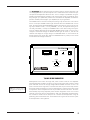
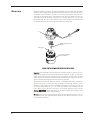
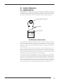
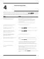
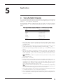
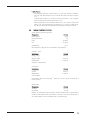
CELL-PORATOR® E. coli Electroporation System Order No. 11613015 (USA) Instruction Manual Table of Contents ! 1. Notices to Customer ................................................................................... 1 1.1 Important Information .............................................................................. 1 1.2 Warnings ................................................................................................ 1 2. Overview ..................................................................................................... 2 2.1 Description ............................................................................................. 2 2.2 Components ........................................................................................... 2 2.3 Introduction to Electroporation.................................................................. 5 2.3.1 Background Information ................................................................ 5 2.3.2 Electrical Principles ........................................................................ 6 2.3.3 Electroporation of E. coli Parameters ............................................... 7 3. Operating Instructions ................................................................................. 8 3.1 3.2 3.3 3.4 3.5 Procedural Overview ............................................................................... 8 Setting Up the Work Area......................................................................... 8 Setup for Temperature Control ................................................................. 8 Setup for Electroporation.......................................................................... 9 Electroporation...................................................................................... 10 4. Troubleshooting Guide ............................................................................. 11 5. Applications ............................................................................................... 13 5.1 Preparing E. coli Cells for Electroporation ................................................ 13 5.2 Preparing DNA for Electroporation into E.coli........................................... 14 5.2.1 Preparing DNA from Ligation Reactions ........................................ 14 5.2.2 Optimizing Electrotransformation Efficiency of E. coli Cells.............. 14 5.3 Medium and Buffer Formulations ............................................................ 15 6. References ................................................................................................. 16 7. Related Products ........................................................................................ 17 8. Additional Information .............................................................................. 18 8.1 8.2 8.3 8.4 8.5 8.6 8.7 Care and Handling................................................................................ 18 Maintenance ......................................................................................... 18 Specifications ........................................................................................ 19 Service ................................................................................................. 20 Equipment Decontamination Certificate................................................... 21 Warranty............................................................................................... 22 Declaration of Conformity and CE Mark.................................................. 22 i Table of Contents Figures 1. CELL-PORATOR E. coli Electroporation System.................................................... 2 2. E. coli Pulser Front Control Panel ..................................................................... 3 3. Single Safe and Disposable Microelectroporation Chambers.............................. 4 4. Basic Design of an Electroporation System........................................................ 5 5. Capacitor Discharge Curve ............................................................................. 6 6. Schematic Diagram of CELL-PORATOR E. coli System Pulse Circuit......................... 7 7. CELL-PORATOR E. coli System Pulse Shape .......................................................... 7 Table Expected Electrotransformation Efficiencies of E. coli Strains with pUC19 DNA ......................................................................................... 13 CELL-PORATOR® and HORIZON® are registered trademarks of Whatman. DELRIN® is a registered trademark of E.I. du Pont de Nemours & Co. DH5αTM and FOCUS® are marks of Invitrogen Corporation. ii 1 Notices to Customer 1.1 ! I m p o r t a n t I n fo r m a t i o n Re ad and car e fully fo llo w m anual ins tr uctio ns . Do not alter equipment. Failure to adhere to these directions could result in personal a n d / o r l a b o r a t o r y h a z a r d s , a s we l l a s i n v a l i d a t e e q u i p m e n t wa r r a n t y . This product is authorized for laboratory research use only. The product has not been qualified or found safe and effective for any human or animal diagnostic or therapeutic application. Uses for other than the labeled intended use may be a violation of applicable law. 1.2 Warnings DANGER! Although designed to prevent accidental exposure to high voltages, this apparatus should always be operated with extreme caution. Do not attempt to defeat safety interlock features designed for user protection. Careless handling could result in a lethal electric shock. This system should be operated by trained personnel only. This manual should be readily accessible to all users. 2. Never operate damaged or leaking equipment. 3. Use only disposable microelectroporation chambers with the CELL-PORATOR E. coli System. 4. Do not attempt to electroporate high-conductivity samples (>1 mM NaCl) with this system. 5. Before operating this system, make sure that all electrical connections are secure and that power cords show no signs of damage. 6. Avoid spilling liquid on or into the apparatus. Do not submerge the apparatus in any liquid. Do not operate the apparatus if it is accidentally wetted. 7. Be sure that the E. coli Pulser is discharged and turned off before connecting or disconnecting the pulse cable. 8. Do not open the instrument case of any CELL-PORATOR E. coli System component. These apparatus contain no user-serviceable parts. 9. Always connect the CELL-PORATOR E. coli System to a 3-wire, grounded AC power outlet. Do not alter the grounded AC power cord provided with the unit. Do not use a two-wire receptacle with an adapter. This could create a serious electrical hazard for persons using this unit. 10. For maximum safety, always operate this system in an isolated, low-traffic area that is not accessible to unauthorized personnel. 11. Certain reagents indicated for use in this manual are of a hazardous nature. The researcher is cautioned to exercise care with these reagents and with the equipment used in these procedures, following the manufacturers' safety recommendations. 12. This system is designed for use at room temperature. Do not set up for operation in a cold room or other low-temperature environment. 1. 1 2 Overview 2.1 Description The CELL-PORATOR E. coli Electroporation System is an electroporation device designed to introduce DNA into Escherichia coli with optimal efficiency, reproducibility, safety, and convenience. This system is capable of generating field strengths as high as 20,000 V/cm (3.0 kV/0.15 cm), and of achieving transformation efficiencies of >1 × 10¹⁰ transformants/µg pUC19 DNA. This manual provides instructions for proper setup and operation of the CELL-PORATOR E. coli Electroporation System and its components, along with protocols for the preparation and electroporation of electrotransformable E. coli strains. 2.2 Components The CELL-PORATOR E. coli Electroporation System is designed to function as a complete, integral system, providing the highest possible degree of safety and convenience for the electroporation of E. coli cells. Each system component is engineered for durability and ease of use. Refer to Figure 1 to identify the following features and components: E. coli Pulser Single Safe with attached pulse cable Disposable Microelectroporation Chambers (not shown) Instruction Manual (not shown) Many of these components are also available separately. For ordering information, refer to Chapter 7, Related Products. E. coli Pulser VO LT AG C EL E (k V) LIF L E. c- POR oli ATO P R CH uls er AR E EleCO ctBR roLpEl TE oecratrop CH tioornat N AiopnpA OL appraarat OG tuuss IES GIB LO W GE REA MED DY IUM HIG H TR IGG ER RAN GE I C Sin TM gle EL Sa L fe P TE C HN O LO G IE S LIF E Single Safe with attached pulse cable O R A TO R TM O Figure 1. CELL-PORATOR E. coli Electroporation System. 2 The E. coli Pulser delivers electrical pulses to bacterial cells by capacitor discharge. The unit is equipped with a 2 µF fixed capacitor and a 4 kΩ internal shunt resistor that provide optimal electroporation efficiencies of E. coli at a voltage of 2,500 VDC using disposable microelectroporation chambers. The internal power supply is capable of generating voltages up to 3,000 VDC; between the raised bosses of disposable microelectroporation chambers, field strengths up to 20,000 V/cm may be generated. The POWER switch on the front control panel (see figure 2) connects the E. coli Pulser to the line current (the POWER indicator light illuminates when the POWER switch is set to ON). The three-position VOLTAGE RANGE selector switch may be used to vary the voltage output between LOW (~1.5 kV), MEDIUM (~2.5 kV, the optimized setting for E. coli cells), and HIGH (~2.9 kV). The CHARGE button is then used to charge the capacitor to the voltage determined by the VOLTAGE RANGE selector switch. Once the unit is charged to the desired voltage, the READY indicator light will come on, and the LCD voltmeter will display the charge voltage. The TRIGGER button is used to deliver the desired voltage to the single safe. When the TRIGGER button is pushed, a tone sounds to indicate that the voltage is delivered. CELL- PORATOR E.coli Pulser READY TRIGGER CHARGE VOLTAGE (kV) MEDIUM LOW HIGH I O VOLTAGE RANGE LIFE POWER TECHNOLOGIES G ElIBCO ectroBRL poraElectroporation tion Apparatus Apparatus Figure 2. E. coli Pulser Front Control Panel. Note: Do not freeze the base assembly. Expansion of freezing water can cause irreparable damage to the base unit. Electroporation occurs within the single safe, which contains a slot for one disposable microelectroporation chamber (see figure 3). The lid of the single safe includes a coaxial pulse cable that connects to the high voltage PULSE OUTPUT connector on the E. coli Pulser. The base of the single safe is a thermal mass that may be used to help maintain the desired sample temperature of 4°C for electroporation. Unscrewing the base reveals a temperature control compartment that may be filled with 20 ml of water. The entire base assembly may be kept separately under constant refrigeration at 4°C or on ice and removed to the work area for electroporation. After each disposable microelectroporation chamber is loaded into the base, the lid is oriented for electroporation using the positioning post and electrode rivets. The threaded outer ring that secures the lid in place for electroporation is then tightened. 3 Overview Radiation-sterilized, individually packaged, disposable microelectroporation chambers (see figure 3) are designed for high transformation efficiencies of E. coli and other bacterial samples. These chambers are made of translucent polypropylene and have leakproof caps to allow mixing of the cell suspension. Each of these chambers contains two integral flat aluminum electrodes, separated by an average distance of 0.15 cm. The two rivets through the cap of each chamber make contact with both the electrodes and the spring-loaded contacts of the single safe lid when the lid is closed. Sin Ce gle Saf ll - P e ora tor ® Lid Disposable Microelectroporation Chamber Positioning post Base (contains temperature control compartment) F i g u r e 3 . S i n g l e S a f e a n d D i s p o s a b l e Mi c r o e l e c t r o p o r a t i o n C h a m b e r s . Important: Each disposable microelectroporation chamber should be used only once for reliable and consistent results. Autoclaving distorts the chambers and does not remove or destroy residual DNA or other material in the crevices between chamber walls and electrodes. Agents such as bleach that destroy DNA and other organic compounds will damage the aluminum electrodes and alter their electrical properties. For purposes of this manual, all CELL-PORATOR E. coli Electroporation System components should be used only in conjunction with one another as instructed. However, certain alternative configurations may also be possible using other CELL-PORATOR products that are not part of this system (e.g., E. coli pulser with chamber safe, chamber rack, and pulse cable; single safe with pulse control, and voltage booster); please call the Service Department or Technical Support (see Chapter 8.4 for numbers) for additional details and precautions. Warning: Under no circumstances should any CELL-PORATOR product be used in conjunction with any other type of electroporation apparatus from other manufacturers, or any other laboratory equipment. 4 2.3 I nt r o d uc t io n t o E le c t r o p o r a t io n 2.3.1 Background Information Electroporation is a technique for rendering cell membranes temporarily permeable to macromolecules such as DNA by exposing cells to a brief electrical pulse or pulses of high field strength. This technique requires suspending cells between two electrodes to which a controlled, unidirectional electrical pulse is applied from a power supply (see figure 4). Power supply/pulse generator Electrodes Cell suspension Fi g ur e 4. B a s ic De s i g n o f a n E l e c t r o p o r a t io n S y s t e m . The electroporation technique originated from studies of electric field effects on biopolymers and organelle membranes. In these studies, homogeneous electric field pulses induced or enhanced material exchange through membranes (13) and also caused membranes to fuse when in close contact with each other a phenomenon termed electro-cell fusion (4,5). The first successful transfer of DNA into mammalian cells by electroporation was described in 1982 (6). Since then, this method has been used successfully for introducing foreign DNA into mammalian, plant, and microbial cells (714). More recently, other high-and low-molecular-weight molecules such as RNA (15), proteins and dyes (16), and nucleotides (17) have been introduced into cells by this method. The molecular mechanism of electroporation is not well understood. It is assumed that an electric field induces a potential difference across the membranes of the cells, exerting pressure on, and subsequently thinning, the membrane. When the induced potential difference is increased beyond a critical point, localized breakdown of the membrane (pore formation) is thought to occur. If the field strength and duration of the electric pulse is not too great, the pores close again and the cell survives; excessive field strength or pulse length, however, can irreversibly damage the membrane and lyse the cells. 5 Overview 2.3.2 Electrical Principles Two methods can be used to apply the pulse for electroporating cells. The output of a power supply can be used directly, applied across the sample for a length of time determined by an electronic or mechanical switch. Alternatively, the output of the power supply can be used to charge a capacitor (an electrical reservoir) to a selected initial voltage, which is then released as a pulse of electrical current through the sample; this is the method used with the CELL-PORATOR E. coli System. Note: The two pulsing methods make different demands on power supplies and may require different experimental conditions for optimal results. The most important electrical parameters in an electroporation experiment are field strength and pulse length. Field strength [expressed in volts per centimeter (V/cm)] is defined as the voltage applied by the power supply to the electrodes, divided by the distance between the electrodes. The field strength is determined by the design of the power supply and the shape and dimensions of the sample chamber. Pulse length is determined by the combination of capacitance [expressed in farads (F)] and resistance [expressed in ohms (Ω)] in a circuit. Capacitance depends on the incorporation of capacitors in the circuit; resistance is largely determined by the sample. In the capacitor charge pulsing method, the voltage of the pulse starts at the initial value and decays exponentially as a function of time, according to the following equation: V(τ) = V0eτ/RC [1] where V0 is the voltage at time zero, e is a constant (2.72), R is the resistance (Ω), and C is the capacitance (F). A plot of this function is shown in figure 5. Voltage Vo e-1 Vo 1 RC Pulse Length 2 RC 3 RC Time F i g u r e 5. C a p a c i t o r Di s c h a r g e C u r v e . The pulse length of a capacitor discharge is defined as the time required for the voltage to drop to 1/e (0.37) of its original value. The pulse length (τ) can be calculated from equation [1]: τ = RC [2] where τ is expressed in seconds (s), R is expressed in Ω, and C is expressed in F. In the CELL-PORATOR E. coli pulser, an internal DC power supply charges a 2 µF capacitor to the desired voltage, and the stored energy is then discharged as a controlled electrical pulse through the disposable microelectroporation chamber and a parallel internal resistor. A simplified diagram of this control circuit is shown in Figure 6. 6 Internal Resistor Capacitor DC Power Supply Disposable Microelectroporation Chamber Figure 6. Schematic Diagram of CELL-PORATOR E. coli System Pulse Circuit. 2.3.3 Electroporation of E. coli Parameters Efficient electroporation of E. coli (1821) requires high sample density (1 × 10¹¹ cells/ml) and field strengths as great as 20,000 V/cm. Transformation efficiencies achieved with this process may be 10 times greater than with cells rendered competent by chemical methods (22). Using the plasmid pUC19 and certain E. coli strains that have been rendered electrotransformable, efficiencies of >1 × 10¹⁰ transformants/µg pUC19 DNA may be obtained (18). In fact, such efficiencies are routine with derivatives of the E. coli strain MC1061 (23,24). Another advantage of the electrotransformation procedure is that a single reaction can generate over 109 transformants from as little as 50 ng of input plasmid DNA (18). These two factors (high efficiency and high saturation capacity) make electroporation the method of choice for the construction of large cDNA libraries from limiting input DNA, or any other application in which DNA is the limiting factor such as plasmid rescue (24), construction of genomic banks (25), or working with methylated cDNA (26). In electroporation of high-resistance samples such as electrotransformable cells, pulse lengths (τ) are approximately proportional to the value of the internal shunt resistor. The capacitive decay shape of a pulse generated by the E. coli pulser is shown in figure 7. For 20 µl samples suspended in 10% glycerol in water, the pulse length at all three VOLTAGE RANGE settings is ~10 ms. Volts 1/ e Time Figure 7. CELL-PORATOR E. coli System Pulse Shape. 7 3 Operating Instructions 3.1 Procedural Overview The basic steps of an electroporation experiment using the CELL-PORATOR E. coli Electroporation System are as follows: 1. Render cells electrotransformable (see Chapter 5) or purchase electrotransformable cells. 2. Add DNA to cells. 3. Electroporate. 4. Transfer the cells into the appropriate medium. 5. Select for transformants. 3.2 Setting Up the Work Area If possible, the CELL PORATOR E. coli Electroporation System should be set up for operation in, or at least close to, a laminar flow hood, which allows transfer of cells and media to and from the disposable microelectroporation chambers under reasonably sterile conditions. To this end, the CELL-PORATOR E. coli Electroporation System is designed to be transported easily and to occupy minimal bench space. 3.3 S e t up fo r T e m p e r a t ur e Co n t r o l The base of the single safe is a thermal mass that may be used to help maintain the desired sample temperature of 4°C for electroporation. Once the following steps have been completed, the base may be kept indefinitely >4°C refrigeration or on ice, being removed to room temperature only for the duration of setting up and performing the electroporation reaction. After equilibrating to 4°C, the base will remain stable at ~4°C for ~30 min at room temperature. 1. 2. 3. 4. 5. 6. 8 Remove the single safe lid from the base by turning the threaded outer ring counterclockwise and lifting the lid away. Unscrew the two halves of the base. Invert the upper half of the base to reveal the temperature control compartment. Fill the temperature control compartment with 20 ml of water. Thread the lower half of the base snugly back onto the upper half. Return the reassembled base to the upright position. If any leaking occurs at the joint between the two halves, twist them to tighten the seal. If leaking persists, please call the Service Department or Technical Support. Place the base separately under refrigeration or on ice to bring to 4°C. Note: Do not place the base at 0°C or less. Expansion of freezing water can cause irreparable damage to the base. Periodically check the amount of fluid in the temperature control compartment (and refill, as necessary) to ensure optimal performance. 3.4 S e t u p fo r E l e c t r o p o r a t i o n Before performing the following steps, review Figures 1 through 3, as needed. 1. 2. 3. 4. 5. 6. 7. 8. 9. 10. 11. 12. 13. Place the E. coli pulser, AC power cord, and single safe lid on a flat, uncluttered workspace, at room temperature, away from the risk of splashing or spilling water. Note: The main POWER switch on the E. coli pulser should be in the off (O) position. Connect the pulse cable on the single safe lid to the coaxial PULSE OUTPUT connector on the rear control panel of the E. coli pulser. The connection is made by inserting the end of the cable into the connector, and twisting to lock in place. Plug the AC power cord into the 115 VAC (or 220/240 VAC, depending on the specifications of your unit) INPUT receptacle on the rear control panel of the E. coli pulser. Note: Check that the fuse in the AC INPUT connector is installed and not visibly damaged. Verify that the main POWER switch on the E. coli pulser is set to the off (O) position. Connect the AC power cord to a suitable grounded, 115 V (or 220/240 V, depending on the specifications of your unit) power outlet. Set the VOLTAGE RANGE selector switch to the MEDIUM setting. Recheck all electrical connections. Turn the POWER switch on the E. coli pulser to the on (l) position. Note: The POWER indicator light on the front panel will light up to indicate that the unit is connected to the line current. Remove the single safe base from cold storage and place it in front of the E. coli pulser, with the positioning pole closest to you. Note: This orientation facilitates operation by allowing the pulse cable on the assembled single safe to extend straight back to the E. coli pulser. To test out the equipment functions, begin by orienting the single safe lid over the base using the positioning post and tightening the threaded outer ring to secure the lid in place. Note: Do not load a disposable microelectroporation chamber into the single safe at this time. Press the CHARGE button to charge the capacitor. Note: When the unit is ready to deliver a pulse, the READY indicator light on the front panel will be lit. With the VOLTAGE RANGE selector switch set to MEDIUM, the LCD voltmeter should display a reading of ~2.5 kV. Confirm that the READY indicator light is lit and push the TRIGGER button to deliver the pulse. Note: A tone sounds to indicate that the voltage is delivered, and the LCD voltmeter reading should drop to ~0. Repeat steps 7 and 8 once with the VOLTAGE RANGE selector switch set to LOW, and again with the switch set to HIGH. The only change from the first trial run should be the LCD voltmeter readout prior to delivering the pulse: ~1.5 kV at the LOW setting, and ~2.9 kV at the HIGH setting. Check the voltmeter to make sure the capacitor is discharged (the LCD voltmeter should read ~0), and turn the POWER switch on the E. coli pulser to the off (O) position. Disconnect the E. coli pulser from the AC outlet. Remove the single safe lid from the base and return the base to cold storage (4°C) until needed. 9 Operating Instructions 3.5 1. 2. 3. 4. 5. 6. 7. 8. 9. 10. 11. 12. 13. 14. 15. 16. 10 Electroporation Mark the required number of culture tubes and add 1 ml of S.O.C. medium to each. Keep these tubes to one side at room temperature, for use later in this protocol. Place cells, DNA, and the required number of sterilized 1.5 ml microcentrifuge tubes on ice. Remove the required number of disposable microelectroporation chambers from their plastic pouches and place them on ice. Note: At this and all subsequent steps, take care to avoid contaminating the chambers during handling. In sterilized microcentrifuge tubes, prepare the cell-DNA mixture to be electroporated. For additional information, please refer to Chapter 5. Once sample preparation is complete, repeat steps 2 through 7 of the preceding protocol. Open a disposable microelectroporation chamber, gripping the sides of the cap. Hold back the cap of the chamber with your index finger, and using a micropipette, pipet 20 µl of the cell-DNA mixture between the bosses of the chamber. Apply the sample slowly, first making contact with one boss, and then drawing the sample over to the other. Note: We recommend practicing the loading technique with 20 µl of a sterilized 20% solution of glycerol in water before attempting to load critical samples. Close the cap of the disposable microelectroporation chamber and gently place the loaded chamber into the single safe base. Orient the single safe lid over the base using the positioning post and electrode rivets (see figure 3). Tighten the threaded outer ring to secure the lid in place for electroporation. Note: Be careful not to crossthread the outer ring; poor electrical contact and loss of the sample may result. Press the CHARGE button to the capacitor. Note: When the unit is ready to deliver a pulse, the READY indicator light on the front panel will be lit. With the VOLTAGE RANGE selector switch set to MEDIUM, the LCD voltmeter should display a reading of ~2.5 kV. Confirm that the READY indicator light is lit and push the TRIGGER button to deliver the pulse to the sample. Note: A tone sounds to indicate that the voltage is delivered, and the LCD voltmeter reading should drop to ~0. Loosen the threaded outer ring and remove the single safe lid. Gently lift out the disposable microelectroporation chamber for further processing of the sample. After removing the disposable microelectroporation chamber from the single safe, carefully open the cap. Using a micropipette, remove the sample from the electrode bosses, and place into a culture tube containing 1 ml of S.O.C. medium (from step 1 of this protocol). Express samples for 1 h in an incubator shaker at 37°C, 225 rpm. Plate the cells on selective medium and select for transformants. For additional samples, repeat steps 5 through 12. Once the experiment is finished, check the voltmeter to make sure the capacitor is discharged (the LCD voltmeter should read ~0) and turn the POWER switch on the E. coli pulser to the off (O) position. Disconnect the E. coli pulser from the AC outlet. Return the single safe base to cold storage (4°C) until needed. Use a damp cloth or paper towel to wipe off any spills from the instruments. Store the components in a dry, noncorrosive environment. 4 Troubleshooting Guide Many apparatus problems can be solved by carefully following the instructions in this manual. Some suggestions for troubleshooting are given in this chapter. Should these suggestions not resolve the problem, call the Service Department or Technical Support (see Chapter 8.4 for numbers). If the unit must be returned for repair, contact our service department, the technical support or your local distributor for shipping instructions. Include a full description of the problem. Problem Equipment: The POWER indicator light does not come on, and the LCD voltmeter shows no reading Comment Verify that the POWER switch is set to the on (l) position. Verify that the AC power cord is securely plugged into the VAC INPUT connector on the rear control panel and into a suitable wall outlet. The fuse in the VAC INPUT connector may have tripped. Remove and replace it, as necessary. The AC outlet circuit may be tripped. Check it with other equipment. The POWER indicator light does not come on, but the LCD voltmeter shows a reading The POWER indicator light bulb is burned out. The POWER indicator light comes on, but the LCD voltmeter shows no reading Contact the Service Department or Technical Support. After pressing the CHARGE button, the LCD voltmeter shows no increase in voltage and the READY light does not come on Contact the Service Department or Technical Support. After pressing the CHARGE button, the LCD voltmeter displays the expected value, but the READY light does not come on The POWER indicator light bulb is burned out. Nothing happens when the pulse is triggered (no tone heard, no change on the LCD voltmeter) Verify that the READY indicator light is on before pressing the TRIGGER button. Contact the Service Department or Technical Support. A loud crack is heard at pulse discharge Arcing occurred in the electroporation chamber. Turn off and unplug the E. coli pulser. Disconnect the single safe and examine it for damage. Remove and discard the chamber. If the problem recurs, sample conductivity may be too high (see comments in Procedure troubleshooting). The temperature control compartment is leaking fluid Check that the upper and lower halves of the single safe base are screwed together snugly. Tighten by turning against each other. Refill the temperature compartment, if necessary. Examine the O-ring between the two halves of the base. If it appears damaged or degraded, or if it does not sit properly in its groove in the lower half of the base, call for a replacement. If leaking persists, call the Support Service Department or Technical 11 Problem Comment Procedure: When the chamber is opened, the sample is splattered over the inside of the chamber Sample conductivity is too high. Reduce the ionic strength of the sample (see Section 5.2). Cells run down inside of chamber, instead of forming a bead between the bosses Use a micropipette with a delivery system that allows you to easily control the rate that the sample is applied between the bosses. Apply the sample slowly, first making contact with one of the bosses, and then drawing the sample out to the other boss. Do not try to electroporate more than 20 µl at one time. Cells are slightly foamy after being pulsed This condition is normal in electroporation of E. coli. However, to verify that the field strength is not too high, reduce the VOLTAGE RANGE setting and compare the cell viability and transformation obtained. Cells are obviously lysed after being pulsed The field strength was substantially too high. Reduce the VOLTAGE RANGE setting. Reduce the conductivity of the sample. Do not attempt to electroporate highconductivity samples (>1 mM NaCl) with this system. No transformants result when cells are pulsed with a known DNA Verify that all electrical connections are correct. Verify that the outer ring on the single safe lid is not being cross-threaded, resulting in poor electrical contact. All components should be snug when the ring is properly tightened. Test a batch of cells of known efficiency Transformation efficiency is less than expected (or some other symptom of incorrect voltage setting) If VOLTAGE RANGE selector switch is set to HIGH or LOW, reset to MEDIUM and repeat electroporation. If VOLTAGE RANGE selector switch is set to MEDIUM, compare results with those obtained using the HIGH and LOW settings. 12 5 Applications 5.1 Preparing E. coli Cells for Electroporation E. coli cells suitable for high-efficiency transformation by electroporation can be prepared from log-phase cultures by washing the cells twice and resuspending them at a high cell density (~ 1 × 10¹¹ cells/ml) in 10% glycerol. The transformation efficiency of different strains will vary greatly. In our tests, the protocol that follows yields 1 × 10¹⁰ transformants/µg pUC19 DNA with a number of strains (table). T a b l e . E xp e c t e d E l e c t r o t r a n s f o r m a t i o n E f f i c i e n c i e s o f E . c o l i S t r a i n s wi t h p U C 19 D N A. Strain Efficiency (transformants/µg)a HB101 LE392 K802 JM109 MC1061 DH5αTM 1.0 to 1.8 × 10¹⁰ 1.5 to 3.8 × 10¹⁰ 1.3 to 2.4 × 10¹⁰ 0.5 to 1.1 × 10¹⁰ 4.0 to 7.0 × 10¹⁰ 0.5 to 1.6 × 10¹⁰ aAll values are based on a sample size of 20 µl and a field strength of ~16.6 kV/cm. 1. Use a fresh colony of cells to inoculate 50 ml of S.O.B. medium (without magnesium) (see Section 5.3) in a 500 ml flask. Grow cells with vigorous aeration overnight at 37°C. 2. Dilute 0.5 ml of cells into 500 ml of S.O.B. medium (without magnesium) in a 2.8 L flask. Grow for 2 to 3 h with vigorous aeration at 37°C until OD550 = 0.8. 3. Harvest cells by centrifuging at 5,000 rpm (2,600 × g) in a GSA or GS3 rotor for 10 min. 4. Wash the cell pellet by resuspending in 500 ml of sterilized, ice-cold WB (10% Ultra Pure glycerol, 90% distilled water, v/v). Centrifuge the cell suspension at 5,000 rpm (2,600 × g) for 15 min and carefully pour off the supernatant as soon as the rotor stops. Note: Cells washed in WB do not pellet well. If the supernatant is turbid, increase the centrifugation time. 5. Repeat step 4, in its entirety. 6. Resuspend the cell pellet in WB to a final density of 200 to 250 OD550 units (~1 to 2 ml). Usually, no additional WB needs to be added to the cell pellet; it can be resuspended in the WB that remains in the centrifuge bottle. Cells can be used immediately or can be frozen in 200 µl aliquots in microcentrifuge tubes using a dry ice-ethanol bath. Store frozen cells at 70°C. Note: A greater volume of lower-efficiency cells can be obtained by resuspending the cells in WB to 10 ml instead of 2 ml. These cells, which typically will yield 5- to 10-fold fewer transformants/µg, may be frozen in 0.5 ml aliquots. 7. Aliquot 20 µl samples of cells (not frozen) into sterilized microcentrifuge tubes. Add 1 µl of DNA (see Section 5.2.1) and mix with the pipette tip. 8. Use a micropipette to suspend each cell-DNA sample between the electrode bosses of a disposable microelectroporation chamber and perform electroporation as described in Chapter 3. 13 Applications 5.2 Preparing DNA for Electroporation into E. coli Taking extra care in the preparation of DNA for high-voltage electroporation into E. coli will improve both transformation efficiency and consistency. DNA used for transformation must be free of phenol, ethanol, and detergents. In addition, electroporation is more efficient if the DNA is in a buffer of very low conductivity, such as 0.5x TE. If DNA is not in a low-conductivity buffer (e.g. 1 mM NaCl), it should be precipitated with ethanol and resuspended in 0.5x TE buffer prior to transformation, as described below. It is important to remember that very small volumes of the ethanol-buffer mix have a high concentration of ions. Remove the ions present in the remaining ethanol-buffer solution by washing with 70% ethanol. When working with small quantities of DNA, it may be preferable to remove as much of the ethanol-buffer mix as possible, recentrifuge the tube briefly, and then carefully remove all of the remaining ethanol mix with a micropipette. Transfer RNA (5 to 10 µg) can be used as a carrier. 5.2.1 Preparing DNA from Ligation Reactions Techniques for precipitating DNA are described in references 27 and 28. 1. To a 20 µl ligation reaction, add 2 µl of 3 M sodium acetate (pH 7.0) and mix. Add 44 µl of 95% or 100% ethanol and mix. 2. Centrifuge for 15 min at room temperature or at 4°C at the maximum speed of the microcentrifuge (e.g., 12,000 × g). Remove the supernatant with a micropipette. 3. Add 60 µl of 70% ethanol and centrifuge for 15 min. Remove the supernatant with a micropipette. 4. Dry the pellet briefly under a vacuum. 5. Using a micropipette, resuspend the pellet in 20 µl of 0.5x TE buffer. To avoid contact with any salts dried further up on the side of the tube, wet only the part of the tube immediately around the pellet. 6. Transfer the resuspended DNA to a new microcentrifuge tube and add to cells, as specified in Section 5.1. 5.2.2 Optimizing Electrotransformation Efficiency of E. coli Cells VOLTAGE RANGE Setting. The CELL-PORATOR E. coli System is designed to optimize 14 these parameters for electroporation of E. coli cells. With the VOLTAGE RANGE selector switch on the E. coli pulser set to MEDIUM (~2.5 kV), the fixed capacitance of 2 µF, and internal parallel resistance of 4 kΩ, E. coli cell-DNA mixtures prepared and electroporated, as described, should yield consistently high transformation efficiencies. Although field strength may be varied by turning the VOLTAGE RANGE selector switch to the LOW or HIGH setting, this step should be performed only following analysis of transformation efficiencies obtained at the MEDIUM setting (see Chapter 4). Cell Density. Because the resistance of the circuit is largely determined by the sample, varying the density of the cell suspension may affect transformation efficiency. For E. coli, the optimal cell density exceeds 1 × 10¹¹ cells/ml, although transformation efficiency is still efficient at 1 ×10¹⁰ cells/ml (109 transformants/µg pUC19 DNA). Cell Physiology. Cell physiology can also have a great impact on transformation efficiency. In initial experiments, E. coli cells should be grown in a rich medium and harvested early in the logarithmic phase; optimal conditions may then be determined by growing the cells in different media and harvesting at different stages of growth. Temperature. The transformation efficiency of electroporation of E. coli is optimal when the temperature is ~4°C. Cells, DNA, and disposable microelectroporation chambers should be kept on ice. The single safe base, with its temperature control compartment filled with 20 ml of water, should be equilibrated to 4°C prior to electroporation. Other Factors: Transformation efficiency is reduced when >1 µl of 0.5x TE buffer is added to 20 µl of cells (formulations for 0.5x and 50x TE buffers are listed in Section 5.3). Transformation frequency is reduced at least 10-fold when >1 µl of ligation buffer is added to 20 µl of cells (see Section 5.2.1). After electroporation, cells should be diluted into 1 ml of S.O.C. medium (see Section 5.3). The cells should then be shaken for 1 h at 37°C to allow expression of the transformed phenotype before being plated on selective medium. 5.3 Me d i u m a n d B u f f e r F o r m u l a t i o n s S.O.B. Medium (without magnesium) Component Bacto-tryptone Bacto-yeast extract Amount 20 g 5g NaCl 0.584 g KCl 0.186 g distilled water to 1 L Mix components, adjust pH to 7.0 with NaOH, and autoclave. 2 M Mg++ stock Component Amount MgCl26H2O 20.33 g MgSO47H2O 24.65 g distilled water to 100 ml Autoclave or filter-sterilize. 2 M glucose Component glucose distilled water Amount 36.04 g to 100 ml S.O.C Medium Filter-sterilize. Add 1 ml of 2 M Mg++ stock and 1 ml of 2 M glucose to 98 ml of S.O.B. medium. 50x TE Buffer Component Amount Tris base 12.11 g Na2EDTA 3.72 g Dissolve Tris and EDTA in 100 ml of water. Titrate with HCl to pH 7.4. Bring volume to 200 ml with distilled water. Filter-sterilize or autoclave. For 0.5x TE buffer, add 1 ml of 50x TE buffer to 99 ml of distilled water, and filter-sterilize. 15 6 References 1. 2. 3. 4. 5. 6. 7. 8. 9. 10. 11. 12. 13. 14. 15. 16. 17. 18. 19. 20. 21. 22. 23. 24. 25. 26. 27. 28. 16 Neumann, E. and Katachalsky, A. (1972) Proc. Natl. Acad. Sci. USA 69, 993. Neumann, E. and Rosenheck, K. (1972) J. Membr. Biol. 14, 194. Zimmermann, U. (1982) Biochim. Biophys. Acta 694, 227. Scheurich, P., Zimmermann, U., Mischel, M., and Lamprecht, I. (1980) Z. Naturforsch. Teil C Biochem. Biophys. Biol. Virol. 37, 1081. Neumann, E., Gerisch, G., and Opatz, K. (1980) Naturwissenschaften 67, 414. Neumann, E., Schaefer-Ridder, M., Wang, Y., and Hofschneider, P.H. (1982) EMBO J. 1, 841. Potter, H., Weir, L., and Leder, P. (1984) Proc. Natl. Acad. Sci. USA 81, 7161. Smithies, O., Gregg, R.G., Boggs, S.S., Koralewski, M.A., and Kucherlapati, R.S. (1985) Nature (Lond.) 317, 230. Reiss, M., Jastreboff, M.M., Bertino, J.R., and Narayanan, R. (1986) Biochem. Biophys. Res. Commun. 137, 244. Toneguzzo, F., Hayday, A.C., and Keating, A. (1986) Mol. Cell. Biol. 6, 703. Tur-Kaspa, R., Teicher, L., Levine, B.J., Skoultchi, A.I., and Shafritz, D.A., (1986) Mol. Cell. Biol. 6, 716. Fromm, M., Taylor, L.P., and Walbot, V. (1986) Nature (Lond.) 319, 791. Bates, G., (1986) unpublished observations. Nishiguchi, M., Langridge, W.H.R., Szalay, A.A., and Zaitlin, M. (1986) Plant Cell Rep. 5, 57. Okada, K., Nagata, T., and Takebe, I. (1986) Plant Cell Physiol. 27, 619. Sowers, A.S. and Lieber, M.R. (1986) FEBS Lett. 205, 179. Sokoloski, J.A., Jastreboff, M.M., Bertino, J.R., Sartorelli, A.C., and Narayanan, R. (1986) Anal. Biochem. 158, 272. Smith, M., Jessee, J., Landers, T., and Jordan, J. (1990) FOCUS® 12, 38. Dower, W.J., Miller, J.F., and Ragsdale, C.W. (1988) Nucleic Acids Res. 16, 6127. Calvin, N.M. and Hanawalt, P.C. (1988) J. Bacteriol. 170, 2796. Hanahan, D., Jessee, J., and Bloom, F. (1991) Methods Enzymol. 204, 63. Hanahan, D. (1983) J. Mol. Biol. 166, 557. Lorow, D. and Jessee, J. (1990) FOCUS 12, 19. Grant, S., Jessee, J., Bloom, F., and Hanahan, D. (1990) Proc. Natl. Acad. Sci. USA 87, 4645. Upcroft, P. and Healy, A. (1987) Gene 51, 69. Dorssers, I. and Postmes, A.M.F.A. (1987) Nucleic Acids Res. 15, 3629. Zeugin, J. and Hartley, J. (1985) FOCUS 7:4, 1. Crouse, J. and Amorese, D. (1987) FOCUS 9:2, 3. 7 Related Products Product Specification Cat. No. USA 11613049 Single Safe 1-chamber capacity 11613064 Chamber Safe 4-chamber capacity 11602018 CELL-PORATOR Electroporation System with 0.4 cm gap disposable electroporation chambers USA 71600019 CELL-PORATOR Electroporation System with 0.15 cm gap disposable microelectroporation chambers USA 11609013 Accessories: E. coli Pulser Related Products: Chamber Rack 11606019 0.4 cm gap Disposable Electroporation Electroporation Chambers pkg. of 50 11601028 0.15 cm gap Disposable Microelectroporation Chambers pkg. of 50 11608031 USA 11612017 USA + CAN 11604022 CELL-PORATOR Voltage Booster Pulse Control 17 8 Additional Information 8.1 Care and Handling The components of the CELL-PORATOR E. coli Electroporation System are fabricated from steel, aluminum, and DELRIN®. As with any laboratory instrument, adequate care ensures consistent and reliable performance. The external surfaces of the components may be cleaned with a damp cloth or paper towel and mild detergent. To remove grease and oils, use a light application of hexane, kerosene, or aliphatic naphtha. Never use abrasive cleaners, window sprays, or rough cloths to clean the components, as these can cause surface damage. Additional cautions: Do not submerge the apparatus in any liquid. Do not allow any electrical parts to come into direct contact with liquid. Do not autoclave or dry-heat sterilize the apparatus. Do not expose the apparatus to phenol, acetone, benzene, halogenated hydrocarbon solvents, undiluted laboratory alcohols, or any corrosive chemicals. Avoid prolonged exposure of the apparatus to UV light. Do not expose the apparatus to heat, moisture, or excessive dust. Important: Each disposable microelectroporation chamber should be used only once for reliable and consistent results, and should be disposed of properly following use. Autoclaving distorts the chambers and does not remove or destroy residual DNA or other material in the crevices between chamber walls and electrodes. Agents such as bleach that destroy DNA and other organic compounds will damage the aluminum electrodes and alter their electrical properties. 8.2 Maintenance The following simple, routine inspection and maintenance procedures will help ensure both the safety and the performance of the CELL-PORATOR E. coli System. 1. 2. 3. 18 Inspect all electrical connections regularly. If the connectors to either the pulse control or the chamber safe do not appear to be in proper working condition, replace the pulse cable or call the Service Department or Technical Support. If the single safe lid or pulse cable shows any signs of wear or damage (e.g., fraying, cracking, nicks, abrasions, or melted insulation), replace it immediately. Do not open the instrument case of any E. coli pulser. These apparatus contain no user-serviceable parts. If you suspect internal problems with any component of this system, call the Service Department or Technical Support immediately. 8.3 Specifications E. coli Pulser Weight............................................................................................... 3.4 kg (7.5 lb) Dimensions (W × L × H) ......................................................... 23.6 × 26.6 × 14.0 cm .............................................................................................. (9.3 × 8.75 × 5.5 in.) Case materials ................................................................................. aluminum, steel Power requirements: Cat. No. 11613-049............................................. 100/115 VAC, 50/60 Hz, 60 W Capacitance..................................................................................................... 2 µF Internal resistor.................................................................... 4 Ω, parallel to chamber Pulse output receptacle ......................................... SHV Receptacle Kings P.N. 1704-1 Maximum pulse current output........................................................................... 40 A Voltmeter ........................................................................ Digital LCD, ±5% accuracy Fuse size................................................................................. 1 A, 5 × 20 mm, T1 A Single Safe Weight............................................................................................... 1.2 kg (2.6 lb) Dimensions (W × H)............................................................................ 7.0 × 12.1 cm ..................................................................................................... (2.75 × 4.75 in.) Temperature control compartment volume ........................................................ 20 ml Construction ............................................................................. stainless steel, DELRIN Pulse cord ............................................ attached, SHV Plug Kings #1705-2, 30" long, ........................................................................................................... coaxial cable Disposable Microelectroporation Chamber Overall dimensions...................................................................... 4.3 × 4.8 × 3.0 cm (W × L × H)................................................................................ (1.7 × 1.9 × 1.2 in.) Construction....................................................................... polypropylene, aluminum Working volume .............................................................................................. 20 µl Average electrode gap................................................................................. 0.15 cm 19 Additional Information 8.4 Service Should you have any problems with this unit, please contact our service department, the technical support or your local Biometra dealer: Service Department Rudolf-Wissell-Straße 14 - 16 D-37079 Göttingen Germany Phone: ++49 - (0)5 51 / 50 88 1- 10 or 12 Fax : ++49 - (0)5 51 / 50 88 1- 11 Mail : [email protected] Technical Support 9101 Yellow Brick Road Suite A Baltimore, MD 21237 USA Phone: 866-793-7671 (toll-free) Fax : 410-574-2380 I n s t r uc t i o n s fo r r e t ur n s h i p m e n t IMPORTANT Before sending the unit back to us, it is urgently necessary also to call our service depart ment, the technical s uppor t or y our local B iometr a dealer ! Return only defective devices. For technical problems which are not definitively recognisable as device faults please contact the Service Department or Technical Support. Use the original box or a similarly sturdy one. Label the outside of the box with "CAUTION! SENSITIVE INSTRUMENT!" Please enclose a precise description of the fault, which also reveals during which procedures the fault occurred, if possible. Important: Clean all parts of the instrument from residues, and of biologically dangerous, chemical and radioactive contaminants. Please include a written confirmation (use the "Equipment Decontamination Certificate" following on the next page) that the device is free of biologically dangerous and radioactive contaminants in each shipment. If the device is contaminated, it is possible that Biometra will be forced to refuse to accept the device. T h e s e n d e r o f t h e r e p a ir o r d e r will b e h e ld lia b le fo r p o s s ib le d a m a g e s r e s ult in g fr o m ins uffic ie nt de c o ntam inatio n o f the de v ic e . Please enclose a note which contains the following: a) Sender's name and address, b) Name of a contact person for further inquiries with telephone number. 20 8.5 E q uip m e nt De c o nt a m ina t io n Ce r t ific a t e To enable us to comply with german law (i.e. §71 StrlSchV, §17 GefStoffV and §19 ChemG) and to avoid exposure to hazardous materials during handling or repair, will you please complete this form, prior to the equipment leaving your laboratory COMPANY / INSTITUTE____________________________________________________________________________________________ ADDRESS________________________________________________________________________________________________________ TEL NO ____________________________________________FAX NO______________________________________________________ E-MAIL__________________________________________________________________________________________________________ EQUIPMENT If on loan / evaluation Model Serial No ______________ __________________ ______________ __________________ ______________ __________________ ______________ __________________ Start Date: ______________________ Finish Date _____________________ Hazardous materials used with this equipment ________________________________________________________________________________________________________________ ________________________________________________________________________________________________________________ ________________________________________________________________________________________________________________ Has the equipment been cleaned and decontaminated? YES / NO (delete) Method of cleaning / decontamination ________________________________________________________________________________________________________________ ________________________________________________________________________________________________________________ ________________________________________________________________________________________________________________ NAME ____________________________________________POSITION ____________________________________________________ (HEAD OF DIV./ DEP./ INSTITUTE / COMPANY) SIGNED ___________________________________________DATE_________________________________________________________ PLEASE RETURN THIS FORM TO OR YOUR LOCAL BIOMETRA DISTRIBUTOR TOGETHER WITH THE EQUIPMENT. PLEASE ATTACH THIS CERTIFICATE OUTSIDE THE PACKAGING. INSTRUMENTS WITHOUT THIS CERTIFICATE ATTACHED WILL BE RETURNED TO SENDER. Additional Information 8.6 Warranty warrants apparatus of its manufacture against defects in materials and workmanship, under normal service, for one year from the date of receipt by the purchaser. This warranty excludes damages resulting from shipping, misuse, carelessness or neglect. s liability under the warranty is limited to the repair of such defects or the replacement of the product, at its option, and is subject to receipt of reasonable proof by the customer that the defect is embraced within the terms of the warranty. All claims made under this warranty must be presented to within one year following the date of delivery of the product to the customer. T h i s wa r r a n t y i s i n l i e u o f a n y o t h e r wa r r a n t i e s o r g u a r a n t e e s , e xp r e s s e d o r i m p l i e d , a r i s ing by law or otherwise. m a k e s n o o t h e r wa r r a n t y , e xp r e s s e d o r i m p l i e d , i n c l u d i n g wa r r a n t i e s o f m e r c h a n t a b i l i t y o r f i t n e s s f o r a p a r t i c u l a r p u r p o s e . U n d e r n o c i r c um s t a n c e s s h a l l b e lia b le fo r d a m a g e s e it he r c o ns e q ue n tial, compens ator y , incidental or s pecial, s ounding in negligence, s tr ict liability , br each of wa r r a n t y o r a n y o t h e r t h e o r y , a r i s i n g o u t o f t h e u s e o f t h e p r o d u c t l i s t e d h e r e i n . reserves the right to make improvements in design, construction, and appearance without notice. 8.7 D e c l a r a t i o n o f C o n f o r m i t y a n d C E Ma r k Note: The information outlined in this section applies only to customers located in the European Union (EU). The EU is currently comprised of 15 member countries. This laboratory apparatus is identified with the CE mark. This mark indicates that the product complies to the following EU Directives and Standards: Application of Council Directive(s): 73/23/EEC Low Voltage Directive 89/336/EEC Electromagnetic Compatibility Standards: EN 61010-1:1993 Product Safety EN 50081-1:1992 Emissions EN 50082-1:1992 Immunity Address: Rudolf-Wissell-Str. 30 37079 Göttingen Germany phone: +49-(0)551-50686- 0 fax : +49-(0)551-50686-66 A copy of the Declaration of Conformity certificate is available upon request. 22 Notes 23 Notes 24 Part No. Lot No. 14332 NBEP01-0200