1
How to use Rohde & Schwarz®
IVI.NET instrument drivers
Application Note
This paper is a guide for C# programmers wanting to automate a measurement task using the native
Rohde & Schwarz IVI.NET instrument drivers in Visual Studio development environment.
The IVI (Interchangeable Virtual Instruments) define new level of quality, completeness, usability, and
functionality that reduces the cost of test system development and ownership.
.NET is a programming framework created by Microsoft that developers can use to create applications
more easily. Without writing a single line of code, .NET provides a scalable and powerful environment to
code upon.
Note:
Please find the most up-to-date Application Note on our homepage:
www.rohde-schwarz.com/appnote/1MA268
Application Note
Miloslav Macko
IVI.NET ─ 1MA268_0e
Contents
Contents
1 Introduction............................................................................................ 3
2 Starting with Rohde & Schwarz IVI.NET drivers................................. 5
3 Creating a new Console application.................................................... 8
4 Additional information.........................................................................36
5 Rohde & Schwarz.................................................................................37
Application Note IVI.NET ─ 1MA268_0e
2
Introduction
Required Software
1 Introduction
1.1 Used abbreviations
The following abbreviations are used in this application note:
●
RTx is the name used for both Rohde & Schwarz RTO or RTE Digital Oscilloscopes.
●
API stands for Application Programming Interface - a set of function prototypes,
types and protocols for building software applications.
●
The Repeated Capabilities are referred to as RepCaps.
●
Interchangeable Virtual Instruments are referred to as IVI.
See more at ivifoundation.org
●
The IVI.NET driver is referred to as IVI driver.
●
The driver documentation RsScope.chm help file is referred to as help file.
●
Microsoft Intellisense® is refered to as Intellisense.
1.2 Required Software
To follow the steps described in this Application Note the following additional software
is required:
●
Windows 7/8 32-bit/64-bit operating system
●
Microsoft Visual Studio 2012 or later
●
VISA I/O library (e.g. Rohde & Schwarz VISA), download from:
https://www.rohde-schwarz.com/RS_Visa.html
RsScope driver and the required IVI packages:
●
IVI compliance package 14.0 or newer, download from:
ni.com
●
IVI Shared Components 2.2.1 or newer, download from:
http://www.ivifoundation.org/shared_components/
●
IVI.NET Shared Components 1.1.2 or newer, download from:
http://www.ivifoundation.org/shared_components/
●
RsScope 1.4.2.0 or newer, download from:
IVI.NET RsScope driver
Application Note IVI.NET ─ 1MA268_0e
3
Introduction
Used instruments
1.2.1 32-bit vs 64-bit operating system
While 32-bit operating system allows only for installation of 32-bit software components
and running of only 32-bit applications, 64-bit OS allows for both 32-bit and 64-bit
applications to be used. For this reason, the 64-bit installers install both 64-bit and 32bit components.
1.3 Used software configuration
The software configuration used in this Application Note:
●
Windows 7 64-bit
●
Microsoft Visual Studio 2012
●
Rohde & Schwarz VISA 5.4.10
●
IVI compliance package 14.0
●
IviSharedComponents64_2.2.1
●
IviNetSharedComponents64_Fx20_1.1.2
●
RsScope 1.4.2.0 x64
●
1MA268_RsScopeIVI.NET example project version 1.0.0
1.4 Used instruments
The instruments used in this Application Note:
●
RTO 1044, 4 Channel, Firmware 2.70.1.0
●
Passive Voltage Probe RT-ZP10, Attenuation rate 1:10
The RT-ZP10 is connected to the CH1 input and the Probe Compensation output on
the front panel.
Application Note IVI.NET ─ 1MA268_0e
4
Starting with Rohde & Schwarz IVI.NET drivers
Installation of IVI.NET driver
2 Starting with Rohde & Schwarz IVI.NET
drivers
Rohde & Schwarz provides a range of free Instrument Drivers (follow the link Rohde &
Schwarz drivers) to simplify the development process of instrument remote control
applications. Rohde & Schwarz have been driving the introduction of IVI.NET drivers
as a new standard in the industry. The first IVI.NET driver RsScope was introduced in
08.2013 for the RTO Digital Oscilloscope.
IVI.NET drivers comes in a form of .NET assembly, e.g. for RsScope:
c:\Program Files\Rohde-Schwarz\RsScope\Bin\
RohdeSchwarz.RsScope.Fx40.dll
This application note will focus only on Instrument-specific interface of the drivers.
Currently the IVI.NET drivers are available for the following instruments:
●
Vector Signal Generators: SMW200A, SMVB100A, SMU200A, SMJ100A,
AMU200A, SMATE200A
●
Spectrum Analyzers: FSW, FSV, FPS, FSVR
●
Oscilloscopes: RTO, RTE, RTM2000
●
EMI Test Receivers: ESR, ESRP
●
New family of Power Sensors: NRPxxS(N)
●
Power Supplies: HMC
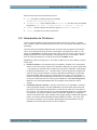
2.1 Installation of IVI.NET driver
For demonstration purposes the driver for Oscilloscopes (RsScope) will be used in this
paper. However, the presented procedures are applicable to all Rohde & Schwarz
IVI.NET drivers.
You have to install the IVI.NET Shared components, IVI Shared Components
and IVI compliance package before the installation of the IVI.NET driver. If you
don't follow this order, the RsScope driver installation will not be successful.
The RsScope driver can be downloaded from: IVI.NET RsScope driver link. On the 64bit OS you have to use x64 installer which will install both 32-bit and 64-bit assemblies
(dlls). On the 32-bit OS use the x86 installer.
Installation paths on 64-bit OS:
c:\Program Files\Rohde-Schwarz\RsScope
c:\Program Files (x86)\Rohde-Schwarz\RsScope
Installation paths on 32-bit OS:
c:\Program Files\Rohde-Schwarz\RsScope
Application Note IVI.NET ─ 1MA268_0e
5
Starting with Rohde & Schwarz IVI.NET drivers
Introduction to IVI drivers
Both locations have the same folder structure:
●
Bin - the folder containing the driver assembly
RohdeSchwarz.RsScope.Fx40.dll
●
Documentation - driver help file folder: RsScope.chm This file is also accessible
through the Start Menu -> Rohde-Schwarz -> RsScope -> RsScope
●
Sample - Simple example Visual Studio project ReadWaveformExample
●
Source - complete source files of the driver.
2.2 Introduction to IVI drivers
The IVI (Interchangeable Virtual Instruments) define new level of quality, completeness, usability, and functionality that reduces the cost of test system development and
ownership.
The first IVI drivers started as IVI-C drivers: the drivers were programmed in ANSI-C.
Later, as the COM technology became more popular, especially due to the C++ language, the IVI-COM drivers were introduced. Today, the main choice of the object-oriented programmers are .NET languages, meaning either C# or Visual Basic. Therefore, the next logical step for IVI was to introduce the IVI.NET drivers.
Regardless of the technology (IVI-C, IVI-COM, IVI.NET), an IVI driver always consists
of two parts:
●
IVI class interface - this interface (API) is mandatory, defined in IVI class specifications. There are several classes in IVI definition depending on type of instrument
- e.g. IviScope for Oscilloscopes, IviSpecAn for Spectrum Analyzers, IviRFSigGen
for RF Signal Generators, etc... The main idea is, that as long as the programmer
sticks to using only this interface, he will be granted the advantage of instrument
interchangeability without having to change the source code. The only thing he
needs to change when swapping the instruments is a database configuration connecting an instrument with an IVI driver (this database is called IVI Config Store).
Because of IVI class standardized API, the program works without a further
change.
●
Instrument-specific interface - this part of the driver is not mandatory. However,
if the programmer wants to use the capabilities of an instrument that are beyond
the scope of class interface specification, he will have to make use of this part of
the IVI driver. From that moment on, the interchangeability feature is compromised.
For example, the IviScope interface class provides the capability of changing the
vertical, horizontal scale, input coupling, basic trigger settings, reading the acquired
traces, etc. But the advanced features that the R&S RTx offers - e.g. math, FFT,
bus protocol analysis, Power analysis, Mixed Signal characterizations are only
available in the instrument-specific IVI driver interface.
Application Note IVI.NET ─ 1MA268_0e
6
Starting with Rohde & Schwarz IVI.NET drivers
Introduction to IVI drivers
The common component of all the IVI drivers - IVI Engine was build to communicate
with ANSI-C libraries only. As a consequence, in order to use ANSI-C IVI class driver
API, e.g. the function:
ViStatus IviScope_init (ViRsrc Logical_Name, ViBoolean ID_Query,
ViBoolean Reset_Device, ViPSession Instrument_Handle);
in your code, you have to use an IVI-C driver. The IVI-COM and IVI.NET drivers need
an adapter that converts the class driver calls to ANSI-C formats. Currently, these exist
only for IVI-COM. IVI.NET adapters are still under development. You can find the IVICOM adapters included in the IVI compliance software package.
Application Note IVI.NET ─ 1MA268_0e
7
Creating a new Console application
3 Creating a new Console application
This chapter describes creating of a new console application from scratch. The complete project 1MA268_RsScopeIVI.NET is available in the attachment to this application note. The entire source code is placed in a file Program.cs, all the code screenshots are taken from that file.
The #region pragma names in the attached example correspond to the chapter
names in this application note.
E.g.: the chapter 3.11 Hardcopy describes the part of the example code enclosed by
the #region 3.11 Hardcopy
To make the hardware set-up easy, the RTx setting is adjusted to measure the front
panel Probe Compensation square signal. Connect the passive probe to the CH1 input
and the Probe Compensation output.
This example performs the following actions:
●
Sets up the RTx channels CH1 and CH2 for measurement of a probe compensation signal (available on a RTx front panel).
●
Sets up the trigger system to normal edge mode.
●
Starts two acquisitions, each with different types of synchronization. The second
one includes a workaround for repeated acquisition in case of unsuccessful one.
●
Performs post-acquisition measurements of amplitude and frequency on both
channels.
●
Reads two waveforms from both channels and stores the results in one csv file.
●
Takes a RTx screenshot and transfers the picture to the Control PC.
●
Reads the RTx folder content.
By performing these actions the following commonly used features are presented:
●
Using of IVI.NET driver Help, that is available here:
Start Menu -> Rohde-Schwarz -> RsScope -> RsScope
●
Creating a new driver session in HISLIP mode:
Chapter 3.3, "Initializing of a HISLIP session", on page 12
●
Changing the common IVI.NET driver session properties - Simulation mode, Status
Checking, Range checking:
Chapter 3.3.1, "driver.DriverOperation.Simulate", on page 13
●
Showing a direct SCPI write/query actions and measuring the execution time:
Chapter 3.5, "Direct SCPI write/query", on page 17
●
Showing how to use Repeated Capabilities:
Chapter 3.6, "Channels setup, using repeated capabilities", on page 18
●
Explaining different type of synchronization methods used for signal acquisitions:
Chapter 3.8.1, "Acquisition synchronization methods", on page 21
Application Note IVI.NET ─ 1MA268_0e
8
Creating a new Console application
Creating new Visual Studio project
●
Working with waveforms - Fetching, changing capacity, reusing waveforms:
Chapter 3.8.3, "Acquisition #2 and converting waveforms", on page 24
●
Showing parsing of an RTx response using Regex object:
Chapter 3.12, "Reading RTx Folder List", on page 30
●
Basic handling of exceptions raised by the driver:
Chapter 3.13, "Handling of exceptions", on page 31
●
Assuming that a certain feature is missing in the driver, extending the RsScope
object by new methods:
Chapter 3.14, "RunSingle() with repeat workaround", on page 34
Chapter 3.15, "Extended method for synchronization", on page 35
Note that the #region pragma names in the attached example correspond to the
chapter names in this application note.
E.g.: chapter 3.11 Hardcopy describes the part of the example code enclosed by the
#region 3.11 Hardcopy
3.1 Creating new Visual Studio project
To create a new project in Visual Studio, select File -> New -> Project:
Figure 3-1: Visual Studio New Project window.
Application Note IVI.NET ─ 1MA268_0e
9
Creating a new Console application
Adding assembly references
3.1.1 Changing the Active solution platform
This settings in Visual Studio allows for changing or adding the target application type:
32-bit (x86) or 64-bit (x64). Avoid using the setting Any CPU and choose the desired
target platform explicitly:
Figure 3-2: Adding new solution platform x64 in Visual Studio 2012.
3.2 Adding assembly references
The next step is adding references to the assemblies:
●
IVI.Driver.dll
●
IVI.Scope.dll
●
RohdeSchwarz.RsScope.Fx40.dll
Application Note IVI.NET ─ 1MA268_0e
10
Creating a new Console application
Adding assembly references
Figure 3-3: Adding reference to an existing assembly You can select multiple assemblies at once.
Assembly paths for 64-bit target application (also used in the attached example):
c:\Program Files\IVI Foundation\IVI\Microsoft.NET\Framework64\
v2.0.50727\IviFoundationSharedComponents 1.1.0\Ivi.Driver.dll
c:\Program Files\IVI Foundation\IVI\Microsoft.NET\Framework64\
v2.0.50727\IviFoundationSharedComponents 1.1.0\Ivi.Scope.dll
c:\Program Files\Rohde-Schwarz\RsScope\Bin\
RohdeSchwarz.RsScope.Fx40.dll
Assembly paths for 32-bit target application:
c:\Program Files (x86)\IVI Foundation\IVI\Microsoft.NET\
Framework64\v2.0.50727\IviFoundationSharedComponents 1.1.0\
Ivi.Driver.dll
c:\Program Files (x86)\IVI Foundation\IVI\Microsoft.NET\
Framework64\v2.0.50727\IviFoundationSharedComponents 1.1.0\
Ivi.Scope.dll
c:\Program Files (x86)\Rohde-Schwarz\RsScope\Bin\
RohdeSchwarz.RsScope.Fx40.dll
After adding the references, you need to add the using directives to the code
(Program.cs) file:
using Ivi.Driver;
using Ivi.Scope;
using RohdeSchwarz.RsScope;
Application Note IVI.NET ─ 1MA268_0e
11
Creating a new Console application
Initializing of a HISLIP session
Afterwards, you can use the RsScope driver methods and properties. In addition, the
Intellisense for RsScope will also be available.
If you choose an incorrect reference processor architecture, you will receive the following warning(s):
Figure 3-4: Visual Studio 2012 mismatching processor architecture warnings.
In this case remove the mismatching assembly and add a correct one.
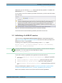
3.3 Initializing of a HISLIP session
HISLIP stands for High Speed LAN Instrument Protocol. A dedicated application
note www.rohde-schwarz.com/appnote/1MA208 describes the HISLIP principles and
differences to VXI-11 in great detail.
Initializing a new session is performed by creating a new RsScope object:
RsScope driver = new RsScope("TCPIP::192.168.1.100::HISLIP0",
true, true, "Simulate=False");
The third parameter in the constructor specify whether to reset the device during the
initialization. You can invoke the reset separately by calling:
driver.Utility.Reset();
The IVI.NET inherent capabilities are organized into several interfaces:
●
IIviDriverOperation: driver.DriverOperation - settings for operation
of the driver
●
IIviDriverIdentity: driver.Identity - general info about the driver
●
IIviDriverUtility: driver.Utility - basic set of utility operations
●
IIviDriverLock: driver.Utility.Lock() - multi thread locking of the session
See the full description (chapter 4.1) here: http://www.ivifoundation.org/downloads/
Architecture%20Specifications/IVI-3.2_Inherent_Capabilities_2015-03-09.doc
Below is the selection of the most-common used IVI Inherent capabilities:
Application Note IVI.NET ─ 1MA268_0e
12
Creating a new Console application
Initializing of a HISLIP session
3.3.1 driver.DriverOperation.Simulate
Default value after initialization: false
When this property is set to true, the driver operates in simulation mode, an instrument
presence is not required:
●
A send command performs no action.
●
A query returns a fixed response that is equal to the default value of the property e.g. reading the for Channel property Range will return the value 0.04 (see the
blue-framed part in Figure 3-5.
Use the Simulate property only if you'd like to change the settings ON and OFF during the run of your application, or in parts of your program.
However, in case you don't have the physical instrument, you need to already switch
the simulation ON during the initialization. This is achieved by initializing with the following option string (the last input parameter):
RsScope driver = new RsScope("TCPIP::192.168.1.100::HISLIP0",
true, true, "Simulate=True");
After that, you cannot switch the simulation OFF anymore.
3.3.2 driver.DriverOperation.IOResourceDescriptor
If you used the logical name in the session init e.g.:
RsScope driver = new RsScope("MyRTO1024", true, true);
string ioResource = driver.DriverOperation.IOResourceDescriptor;
string logName = driver.DriverOperation.LogicalName;
The result of ioResource will be the actual IO-resource descriptor as it is declared in
the IVI Configuration store. The value of logName will be "MyRTO1024". In our case
when we are using the direct IO-resource descriptor, both string values will be identical.
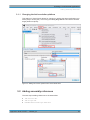
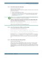
3.3.3 driver.DriverOperation.RangeCheck
Default value after initialization: true
Setting of this property enables/disables the driver functionality of checking whether
the entered value is within the allowed range defined in the driver - for example the
channel property Range has a valid range of values from 0.01V to 10V (red rectangle).
The blue rectangle shows the value of the property returned when the driver is in simulation mode.
Application Note IVI.NET ─ 1MA268_0e
13
Creating a new Console application
Initializing of a HISLIP session
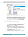
Figure 3-5: Channel property Range with valid values 0.01...10V.
If you try to set value outside this defined range, the driver doesn't send any command
to the instrument and throws the IVINET.Internal.ErrorException.
In rare cases an instrument can accept the values outside the driver-defined valid
range. In this case you can disable the driver range checking and send the value to the
instrument anyway. Since the instrument also has its own checking of valid parameter
values, it will report an error in its error queue. To properly react on instrument errors
you need to set the property
driver.DriverOperation.QueryInstrumentStatus described in the next
chapter to true.
3.3.4 driver.DriverOperation.QueryInstrumentStatus
Default value after initialization: true
If this property is set to true, it causes the driver to query the instrument status byte
("*STB?" command) after every command or query. This brings the advantage of
detecting an error immediately after the command that caused it. It is recommended to
keep the QueryInstrumentStatus set to true.
However, the disadvantage is slightly decreased performance. When you perform a
repeated number of short acquisition where every microsecond counts, set this property to false before the acquisitions, but set it back to true afterwards. This combines
the fast execution with the proper error handling.
Action after reading the instrument status byte: In case an instrument error is detected,
the driver generates an IVINET.Internal.ErrorException.
For more details on handling the exceptions refer to the Chapter 3.13, "Handling of
exceptions", on page 31
Application Note IVI.NET ─ 1MA268_0e
14
Creating a new Console application
Reading basic info
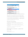
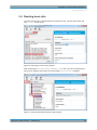
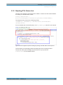
3.4 Reading basic info
To read out how many channels does the instrument have, use the Help Search tab
with "count" search word:
Figure 3-6: Searching for a term in driver help file.
After selecting the RSSCOPE_ATTR_CHANNEL_COUNT item, go to the Contents tab to
see in which interface (tree branch) is the property ChannelCount available:
Figure 3-7: Selected element ChannelCount in Help Contents.
Application Note IVI.NET ─ 1MA268_0e
15
Creating a new Console application
Reading basic info
Therefore, the syntax will be the following:
int channelCount = driver.System.ChannelCount;
Another example is reading out the instrument firmware version - the property
FirmwareVersion also belongs to the System interface:
string fwVersion = driver.System.FirmwareVersion;
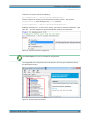
Enabling the Channel 1: To find out the syntax, the best is to use the Intellisense. Type
"driver." and the Intellisense shows all available methods and properties:
Figure 3-8: The driver Intellisense suggestions.
Use CTRL+Space to force the Intellisense suggestions.
The suggested list corresponds to the help file tree structure (the Intellisense shows
the alphabetical order):
Figure 3-9: The driver help tree structure.
Application Note IVI.NET ─ 1MA268_0e
16
Creating a new Console application
Direct SCPI write/query
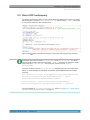
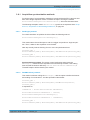
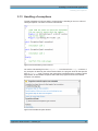
3.5 Direct SCPI write/query
The driver still offers the option of using direct SCPI commands and queries. An example sending the command "SYST:DISP:UPD ON" and the query "*IDN?" performed
in a loop with measuring the execution time:
Figure 3-10: Direct SCPI command write and query example plus measuring the query execution
time.
By default, at the end of each WriteCommand() and QueryCommand() the driver
queries the RTx status with the SCPI query "*STB?". Therefore an attempt to send a
query with the WriteCommand() will cause the instrument error "query
interrupted".
You have to either use the QueryCommand() or disable querying of the status byte
before. A small example of write/read combination with disabled instrument status
querying:
bool oldStatus = driver.DriverOperation.QueryInstrumentStatus;
driver.DriverOperation.QueryInstrumentStatus = false;
driver.Miscellaneous.WriteCommand("*IDN?");
string response = driver.Miscellaneous.ReadCommand();
driver.DriverOperation.QueryInstrumentStatus = oldStatus;
For more details on QueryInstrumentStatus refer to Chapter 3.3.4, "driver.DriverOperation.QueryInstrumentStatus", on page 14
Application Note IVI.NET ─ 1MA268_0e
17
Creating a new Console application
Channels setup, using repeated capabilities
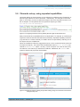
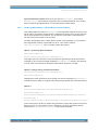
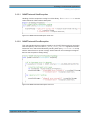
3.6 Channels setup, using repeated capabilities
Horizontal settings of the acquisition can be adjusted by 2 different ways: Resolution or
Record length (see the RTx GUI Horizontal -> Resolution). The example chooses the
latter. In this mode, you have to define the length of the entire acquisition and the number of samples. The acquisition time is a special IVI object type called
Ivi.Driver.PrecisionTimeSpan
Figure 3-11: Configuring Horizontal scale by defining Record length and Acquisition time.
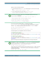
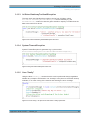
Many instruments have capabilities which are duplicated. For example, an oscilloscope
might have several channels with identical functionality. Repeated capability instances
(e.g. selection of a certain channel) in IVI.NET drivers are specified by selecting one of
the objects from the available list.
When the Intellisense offers the suggestions shown on the screenshot below (methods
for sequence objects) - this means that the addressed object (driver.Channel) represents an IEnumerable object - an array or a list of objects. You need to select only
one element - the channel you would like to address. Afterwards, the Channel subsystem methods and properties are available:
Figure 3-12: Adding the objects indexing. All possible indexing strings are mentioned in the Channel
Subsystem help text.
Application Note IVI.NET ─ 1MA268_0e
18
Creating a new Console application
Channels setup, using repeated capabilities
Options to select a desired subsystem:
●
with the RepCap name (e.g."CH2"), the valid strings are to be found in the help
file:
driver.Channel["CH2"].Enabled = true;
●
with an 0-based index using the method ElementAt(index):
driver.Channel.ElementAt(1).Enabled = true;
The following code snippet creates a list of all available RepCap names for the
driver.Channel subsystem:
Console.Write("\nRepCap '{0}' count {1}, all values: ",
driver.Channel.Name, driver.Channel.Count);
//loop-operation with all the elements
foreach (var element in driver.Channel)
Console.Write("'{0}' ", element.RCKey);
You can now create a variable called CH1 and assign one object
driver.Channel["CH1"] to it in order to use it later for all operations related to
Channel 1, e.g. configuring the basic parameters with the Configure method:
var CH1 = driver.Channel["CH1"];
CH1.Configure (2.000, 0.0,
RohdeSchwarz.RsScope.VerticalCoupling.AC, true);
The same approach can be applied to the second channel:
Figure 3-13: Creating CH1 and CH2 objects, using them later for accessing the subsystems.
The objects CH1 and CH2 are of a type IRsScopeChannel. You can use the explicit
or implicit type declarations. The following two declarations are equivalent:
IRsScopeChannel CH1 = driver.Channel["CH1"];
var CH1 = driver.Channel["CH1"];
Using implicit type is easier than finding out the actual type of the CH1 object. Hovering
a cursor over the word "var" will show the help text for the interface, including the
available RepCap strings:
Channel (CH1, CH2, CH3, CH4, CHExt)
Application Note IVI.NET ─ 1MA268_0e
19
Creating a new Console application
Acquisition and reading waveforms
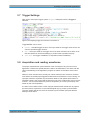
3.7 Trigger Settings
Next section sets up the trigger system Trigger Subsystem with the Trigger A
selected:
Figure 3-14: Configuring Trigger A for Channel 1 and Channel 2.
TriggerModifier can be set to:
●
Normal - standard trigger function, the scope waits for the trigger event until it reaches the specified trigger timeout.
●
Auto - the scope waits for the trigger event, but when it doesn't arrive within a certain time (based on horizontal settings), it performs the acquisition anyway.
●
Free Run - the trigger is disabled, an acquisition starts immediately.
3.8 Acquisition and reading waveforms
The proper measurement synchronization is the critical part of any remote-control
application. Therefore a special attention needs to be dedication to this issue with the
clear understanding of the application progress in relation to the status of the instrument.
While on some instruments it's usually not critical at which exact moment a measurement starts, the oscilloscope-triggered measurement is all about the correct timing. An
improper waveform acquisition synchronization leads to sub-optimal performance or
unreliable results. User might read the waveform out of the oscilloscope at an incorrect
moment - too soon (the result from previous acquisition) or too late (it is already overwritten by the next acquisition).
It is often much harder to filter out the improper measurement results than to prepare
the instrument to capture the correct wanted signal only by proper synchronization.
The next chapter will discuss some of the basic synchronization principles that the
RsScope driver offers.
Application Note IVI.NET ─ 1MA268_0e
20
Creating a new Console application
Acquisition and reading waveforms
3.8.1 Acquisition synchronization methods
For all the types of synchronization methods it is required that the RTx instrument has
been set to single acquisition mode. Therefore the option of using the method
driver.WaveformAcquisition.RunContinuous() will not be discussed here.
The following examples contain IWaveform<T>, types that are explained here: Chapter 3.8.2, "Acquisition #1 and reading waveforms", on page 23.
3.8.1.1
RunSingle() method
For a basic waveform acquisition the driver offers the following method:
driver.WaveformAcquisition.RunSingle();
This method arms the oscilloscope to wait for a trigger and perform a single acquisition. Then, it waits for the acquisition to be finished.
Next step usually involves fetching of one or more acquired waveforms:
waveform_CH1 =
driver.Channel["CH1"].Waveform["W0"].FetchWaveform(waveform_CH1);
waveform_CH2 =
driver.Channel["CH2"].Waveform["W0"].FetchWaveform(waveform_CH2);
Synchronization provided: The remote-control application waits inside the
RunSingle() method until the acquisition has successfully finished. If the waiting
time exceeds the timeout defined by driver.Miscellaneous.OPCTimeout, a
TimeoutException will be raised by the method.
3.8.1.2
ReadWaveform() method
This method combines calling the RunSingle() with the option to define the timeout
and reading of one waveform - see the equivalent codes below:
waveform_CH1 =
driver.Channel["CH1"].Waveform["W0"].ReadWaveform(timeout,
waveform_CH1);
is equivalent to:
oldTimeout = driver.Miscellaneous.OPCTimeout;
driver.Miscellaneous.OPCTimeout = timeout;
driver.WaveformAcquisition.RunSingle();
driver.Miscellaneous.OPCTimeout = oldTimeout;
waveform_CH1 =
driver.Channel["CH1"].Waveform["W0"].FetchWaveform(waveform_CH1);
Application Note IVI.NET ─ 1MA268_0e
21
Creating a new Console application
Acquisition and reading waveforms
Synchronization provided: Same as in the case of RunSingle(), the method
ReadWaveform() waits until the acquisition has successfully finished. If the waiting
time exceeds the provided timeout, a TimeoutException will be raised.
3.8.1.3
RunSingleWithoutWait() + WaitForMeasurementComplete()
This method splits the method RunSingle()to two separate methods where the user
has an option of inserting another action in between the arming of the scope and waiting for the acquisition to be finished. This is often the case when a measurement of
non-periodical event needs to be recorded.
Consider the following case: A DUT (Device Under Test) generates a non-periodical
burst signal after remotely commanded to do so - let's call the method
DUT.GenerateBurst(). How to reliably acquire this signal?
Option 1, producing Race Condition:
DUT.GenerateBurst();
driver.WaveformAcquisition.RunSingle();
This might just work if the DUT is slow enough with generating a signal and the RTx
manages to get to the armed state initiated by ReadWaveform method. The behavior
of such order of commands is undefined and therefore should be avoided.
Option 2, always raising a timeout exception:
driver.WaveformAcquisition.RunSingle();
DUT.GenerateBurst();
Swapping the order will always cause raising of a timeout exception by RunSingle()
method because it waits for a signal that will only be generated after it finishes waiting.
Option 3:
driver.WaveformAcquisition.RunSingleWithoutWait();
DUT.GenerateBurst();
driver.WaveformAcquisition.WaitForMeasurementComplete(timeout);
waveform_CH1 =
driver.Channel["CH1"].Waveform["W0"].FetchWaveform(waveform_CH1);
In this case as first, the RTx is armed and prepared to acquire the signal from the DUT
before the DUT is commanded. The key difference is, that the application passes
through the RunSingleWithoutWait() method without waiting.
Application Note IVI.NET ─ 1MA268_0e
22
Creating a new Console application
Acquisition and reading waveforms
The methods starting with Read always start a new measurement, wait for the results
and then provide the data.
The methods starting with Fetch only provide an actual data without starting any new
measurement.
An actual synchronization is performed after commanding the DUT in the method
WaitForMeasurementComplete() where the RTx trigger system is with certainty
prepared to react on the signal from the DUT.
Synchronization provided: The remote-control application waits inside the
WaitForMeasurementComplete() method until the acquisition has successfully finished. If the acquisition has already finished before this method is called, the method
finishes immediately. If the waiting time exceeds the defined timeout, a
System.TimeoutException will be raised.
3.8.2 Acquisition #1 and reading waveforms
In remote-control application utilizing of continuous measurement mode should be limited to none, there are only very few special cases where it is really justified. Most of
the times it can be substituted for properly synchronized on-request invoked single
measurements.
The following two chapters perform two acquisitions to show reuse of the waveform
resources and the usage of two different synchronization methods.
Acquisition #1:
RunSingleWithoutWait() + WaitForMeasurementComplete(timeout)
Figure 3-15: Acquisition #1 with the option to perform a middle action after arming the RTx.
After this code, the latest waveforms from all enabled channels are available for reading. Compared to other drivers (VXIpnp, LabVIEW) where the traces are read into a
simple array, IVI.NET driver uses an IWaveform<T> interface (or its extensions
IMemoryWaveform<T>, ISpectrum<T>, IMemorySpectrum<T>). <T>stands for
a generic type from which you can choose (equivalents to double array, I32 array, I8
Application Note IVI.NET ─ 1MA268_0e
23
Creating a new Console application
Acquisition and reading waveforms
array...), but not all methods accept all types. For example the method
FetchWaveform() only accepts double or sbyte types.
Initialization of two new waveforms:
IWaveform<double> waveform_CH1 = null;
IWaveform<double> waveform_CH2 = null;
According the IVI.NET specification all functions returning waveforms must also have
waveforms as input parameters. There are 2 main reasons for this:
●
defining the output variable type - in this case the waveform_CH1 is of double
type, hence the output from the FetchWaveform() will be of
IWaveform<double> type as well.
●
it allows for reusing the previously allocated resources - if the waveform_CH1 is
not yet initialized (null), the FetchWaveform(waveform_CH1) will initialize it
with the required capacity (number of samples). With the subsequent calls of
FetchWaveform(waveform_CH1) the method doesn't do any reallocation of the
resources. Therefore, the performance is optimized by reusing the existing ones.
To change the size of the expected waveform (recordLength) you need to use
the propertywaveform_CH1.Capacity. The capacity means maximum capacity;
smaller recordLength can be accommodated without a change. The actual
record length is in a separate property: waveform_CH1.ValidPointCount
In this example this is the first reading of the waveforms - the required capacity is allocated by the FetchWaveform(), because the waveform_CH1 / waveform_CH2
objects have not been yet initialized:
Figure 3-16: First reading of the waveforms.
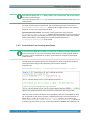
3.8.3 Acquisition #2 and converting waveforms
Second acquisition is done with increased number of samples. To simulate repeating
of an unsuccessful acquisition the driver.WaveformAcquisition.RunSingle()
is wrapped in an extension method Extended_RunSingleWithRepeat(). For more
details refer to Chapter 3.14, "RunSingle() with repeat workaround", on page 34
Application Note IVI.NET ─ 1MA268_0e
24
Creating a new Console application
Acquisition and reading waveforms
Figure 3-17: Acquisition #2 - Extended_RunSingleWithRepeat() method with repeated workaround.
With the fetching of the waveforms you can reuse the objects waveform_CH1 /
waveform_CH2. If the increased capacity is required, you have to change it with the
Capacity property:
Figure 3-18: Fetching the waveforms, reusing of the existing waveforms, but with increased capacity.
RTx allows only for even number of samples. Setting the odd number will cause the
RTx to coerce real number of samples to the closest higher even number (e.g. 1101 ->
1102). Changing the variable newRecordLength from 1100 to 1101 (Figure 3-17)
would cause the FetchWaveform()method to raise an exception
Ivi.Driver.DataArrayTooSmallException, because the actual capacity
required would be 1102 samples.
Notice, that prior to the call of Extended_RunSingleWithRepeat(), the trigger
source is changed to Channel 2. Since the hardware cabling is feeding the Probe
Compensation signal to the Channel 1, the first attempt to acquire a new waveform will
Application Note IVI.NET ─ 1MA268_0e
25
Creating a new Console application
Measurements
result in timeout. The Extended_RunSingleWithRepeat() will give you an option
to change the trigger source back to Channel 1 or reconnect the probe to the Channel
2 and repeat the acquisition. The workaround of repeated unsuccessful acquisition is
very often the case in real remote-control applications.
Conversion to an array object is achieved by using the GetAllElements() method:
Figure 3-19: Reading all the waveform elements into a double array.
The horizontal scale is represented by the waveform properties: StartTime,
EndTime, TotalTime, IntervalPerPoint. Use the Intellisense to explore all the
methods and properties that the IWaveform<T> object offers.
3.9 Measurements
Very often it is not necessary to transfer the entire waveform sample by sample to the
control PC, but instead it is sufficient to analyze the properties of the signal: amplitude,
frequency, pulse width, etc. For this purpose the RTx offers the measurement subsystem.
Measurement is always performed on the last acquired waveform. A change in the
measurement settings immediately produces an updated result (in remote-control
application you need to use a synchronization ("*OPC?" query or "*WAI" command
after a change in measurement settings). It is not necessary to perform a new waveform acquisition.
The following example sets three different measurements on both channels. Although
in manual operation the measurement results are immediately available after switching
them ON, the remote-control operation requires the synchronization using "*OPC?"
query before fetching any measurement result. This is achieved by calling a method
driver.Extended_Synchro() highlighted in the red rectangle:
Application Note IVI.NET ─ 1MA268_0e
26
Creating a new Console application
Measurements
Figure 3-20: Measurements of three different parameters - settings and fetching of the results are
separated by the method driver.Extended_Synchro()
Not using the Extended_Synchro() method might cause a reading timeout during
one of the FetchMainMeasurement() calls, because the result of the measurement
is not available that fast after switching it on. The alternative is including a fixed-time
pause, but it is much more time-efficient to let the instrument to decide how fast it can
proceed.
Please note the difference between calling the method with the parameter SynchroType.WAI and SynchroType.OPC:
driver.Extended_Synchro(SynchroType.OPC) waits inside the method until all
the previous commands have been processed.
driver.Extended_Synchro(SynchroType.WAI) doesn't wait, your program continues immediately, it only tells the instrument that it should not continue with processing any further commands before it has finished all the previous ones. The actual necessary pause will be achieved by waiting for a response of the next query, in this case
the first call of FetchMainMeasurement().
Application Note IVI.NET ─ 1MA268_0e
27
Creating a new Console application
Hardcopy
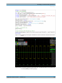
3.10 Exporting the Waveforms to a csv file
This part of the example will export the waveforms to a csv file:
Figure 3-21: Exporting the waveforms to a csv file.
3.11 Hardcopy
This chapter shows the steps for capturing an RTx screenshot and transferring the picture to the control PC. The picture settings can be changed in the set-up part. For this
example, the setting that produces the exact copy of the RTx screen is chosen.
The code snippet below shows the set-up of the hardcopy format, taking a screenshot
with Hcpy.Print() and afterwards transferring the created screenshot file to the
Control PC. If the file with the same name already exists, it will be overwritten.
The method ReadToFileFromInstrument() is universal for file transfer from the
instrument to the Control PC. Note that both parameters of the method require the
entire path including the file name; therefore the target file in the PC can have a different name than the original file. Here, the original file name is
1MA268_screenshot_RTx.png while the target file name is
1MA268_screenshot_PC.png
To transfer a file in the opposite direction: PC -> RTx, use the following method:
driver.DataManagement.WriteFromFileToInstrument (filePathPC,
filePathRTx);
Application Note IVI.NET ─ 1MA268_0e
28
Creating a new Console application
Hardcopy
Figure 3-22: RTx hardcopy code snippet. Included at the end is the transfer of the file from the RTx to
the PC.
Figure 3-23: RTx screenshot transferred to the Control PC - the default PC path is in the example set
to C:\Temp\1MA268_screenshot_PC.png
Application Note IVI.NET ─ 1MA268_0e
29
Creating a new Console application
Reading RTx Folder List
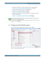
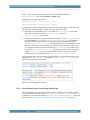
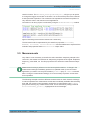
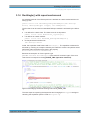
3.12 Reading RTx Folder List
This part of the example code shows how to obtain a content of an RTx folder. Method
for reading of a desired folder content:
string folderContent =
driver.DataManagement.FileDirectoryContent(folderPathRTx);
The response string comes in the following format:
<UsedMemory>,<FreeMemory>,<ParentFolder>,<ParentFolder>,
<FolderContent>
For more details refer to the SCPI query MMEMory:CATalog? in the RTx user manual.
Figure 3-24: Code snippet that performs reading and parsing of the RTx folder content response.
The first match (red rectangle) parses the header part which is always present.
The second match (blue rectangle) is performed in a loop to parse the
folderContent for all available entries.
Application Note IVI.NET ─ 1MA268_0e
30
Creating a new Console application
Handling of exceptions
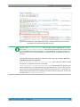
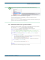
3.13 Handling of exceptions
The big advantage of C# over ANSI-C programming is handling of errors in a form of
raising exceptions. The basic construct is as follows:
Figure 3-25: Visual Studio try-catch construct.
Our entire code starting from the #region 3.3 is enclosed in the try{} construct. If
any exception is raised by the code enclosed within, the program looks for that specific
type of catch {} case. If it exists, the code will be executed and the exception will be
suppressed. All unhandled exceptions will break the program and show the default
exception info window:
Figure 3-26: Unhandled exception window.
Application Note IVI.NET ─ 1MA268_0e
31
Creating a new Console application
Handling of exceptions
3.13.1 IVINET.Internal.VisaException
Handling of all the exceptions coming from VISA library. The VisaErrorCode are the
codes defined in VISA interface description.
Figure 3-27: IVINET.Internal.VisaException catch case.
3.13.2 IVINET.Internal.ErrorException
This code handles all the exceptions raised by the IVI.NET RsScope driver (excluding
VISA exceptions). The error code RS_ERROR_INSTR_SPECIFIC signals an internal
instrument error, that will be followed by sending SCPI query "SYST:ERR?" in a loop
until the instrument error queue is empty. All the read out error messages are appended into the exception message string:
Figure 3-28: IVINET.Internal.ErrorException catch case.
Application Note IVI.NET ─ 1MA268_0e
32
Creating a new Console application
Handling of exceptions
3.13.3 Ivi.Driver.DataArrayTooSmallException
The next catch case handles the exception coming from IVI library called
Ivi.Driver.DataArrayTooSmallException that is raised by e.g. the
FetchWaveform() method in case the given waveform capacity is smaller than the
data to be read from a device:
Figure 3-29: Ivi.Driver.DataArrayTooSmallException catch case.
3.13.4 System.TimeoutException
System.TimeoutException is generated e.g. by the method
driver.WaveformAcquisition.WaitForMeasurementComplete()
Figure 3-30: System.TimeoutException catch case.
3.13.5 Case "finally"
Using the block finally{} ensures that this code is performed always regardless
whether any exception was raised or not. Usually it is the place to call all the cleanup
methods, in our case closing of the session and showing the error message:
Figure 3-31: Case 'finally' - the path of the code which is always performed.
Application Note IVI.NET ─ 1MA268_0e
33
Creating a new Console application
RunSingle() with repeat workaround
3.14 RunSingle() with repeat workaround
An extended method of the RsScope driver is defined as a static method with the following syntax:
public static bool Extended_RunSigleWithRepeat(this RsScope
driver, IRsScopeTrigger trigger, int maxRepeats)
The fact that it can be used as a standard RsScope method is achieved by the following:
●
it is defined in a static class. The class name is not important:
public static class Extensions_of_RsScope{}
●
it is defines as a static method:
public static bool Extended_RunSigleWithRepeat()
●
its first parameter is defined as:
this RsScope driver
Inside, the acquisition itself is done with RunSingle(). The repetition workaround is
achieved by catching an exception raised by the method in case the acquisition wasn't
performed within the defined time (set by the property
driver.Miscellaneous.OPCTimeout).
Because the exception is of more generic type
(IVINET.Internal.ErrorException) the catch will re-raise it again, if the error
code doesn't correspond to the VI_ERROR_TMO (Operation timed-out):
Figure 3-32: RunSingle() method with catching of the code VI_ERROR_TMO.
The next steps are capturing the keystrokes and changing the TriggerA settings or
canceling the acquisition (see the code in Program.cs).
Application Note IVI.NET ─ 1MA268_0e
34
Creating a new Console application
Extended method for synchronization
Notice that the original and the extended methods are treated the same way:
Figure 3-33: RsScope extended methods Intellisense suggestions.
For the extended methods to be available, you need to include the directive:
using RsScopeExtensions;
The RsScopeExtensions is the namespace in which the extension methods are programmed. The class name itself is not important.
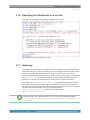
3.15 Extended method for synchronization
Similar to the previous chapter, you can define an extended function for synchronization. The enum SynchroType must be defined in the namespace
RsScopeExtensions as public to be accessible by the main program.
Figure 3-34: Extension method Extended_Synchro() code snippet.
Application Note IVI.NET ─ 1MA268_0e
35
Additional information
4 Additional information
Please send your comments and suggestions regarding this Application Note to:
[email protected]
Using tag “[1MA268]” in the mail subject will help us to quickly identify the topic and
speed up the response process.
Application Note IVI.NET ─ 1MA268_0e
36
Rohde & Schwarz
5 Rohde & Schwarz
The Rohde & Schwarz electronics group offers innovative solutions in the following
business fields: test and measurement, broadcast and media, secure communications,
cybersecurity, radiomonitoring and radiolocation. Founded more than 80 years ago,
this independent company has an extensive sales and service network and is present
in more than 70 countries.
The electronics group is among the world market leaders in its established business
fields. The company is headquartered in Munich, Germany. It also has regional headquarters in Singapore and Columbia, Maryland, USA, to manage its operations in
these regions.
Sustainable product design
●
Environmental compatibility and eco-footprint
●
Energy efficiency and low emissions
●
Longevity and optimized total cost of ownership
Certified Quality Management
ISO 9001
Certified Environmental Management
ISO 14001
Regional contact
●
Europe, Africa, Middle East - [email protected]
Phone +49 89 4129 12345
●
North America - [email protected]
Phone 1-888-TEST-RSA (1-888-837-8772)
●
Latin America - [email protected]
Phone +1-410-910-7988
●
Asia/Pacific - [email protected]
Phone +65 65 13 04 88
●
China - [email protected]
Phone +86-800-810-8228 / +86-400-650-5896
Headquarters
Rohde & Schwarz GmbH & Co. KG
Mühldorfstraße 15 | D - 81671 München
+ 49 89 4129 - 0 | Fax + 49 89 4129 – 13777
www.rohde-schwarz.com
This application note and the supplied programs may only be used subject to the conditions of use set forth
in the download area of the Rohde & Schwarz website.
R&S® is a registered trademark of Rohde & Schwarz GmbH & Co. KG. Trade names are trademarks of the
owners.
Application Note IVI.NET ─ 1MA268_0e
37