1
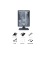
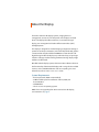
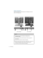
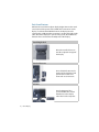
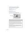
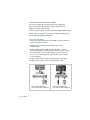
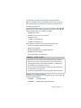
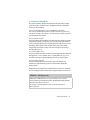
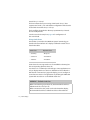
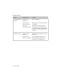
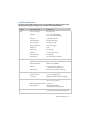
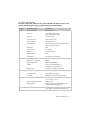
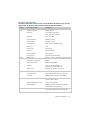
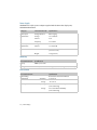
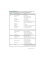
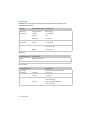
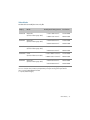
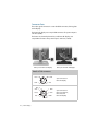
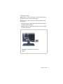
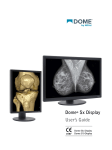
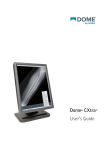
Dome C3i/EX Display
User’s Guide
Solaris Systems
© 2006 Planar Systems, Inc. All rights reserved.
Information in this document has been carefully checked for accuracy; however, no
guarantee is given to the correctness of the contents. This document is subject to
change without notice. Planar provides this information as reference only. Reference
to other vendors’ product does not imply any recommendation or endorsement.
This document contains proprietary information protected by copyright. No part of
this manual may be reproduced by any mechanical, electronic, or other means, in
any form, without prior written permission of the manufacturer.
Planar, Dome, Dome C3i, Dome E2, Dome E3, Dome E3c, Dome E5, Dome DX2,
Dome CXtra, and RightLight are either registered trademark or trademarks of
Planar Systems, Inc. All other trademarks are the property of their respective owners.
020-0377-01A
Contents
Product Information
About the Display
iv
1
Installing the Display
5
Dome CXtra Software
26
Appendix
Index
27
43
Regulatory Compliance
Standard Warranty
45
51
iii
Product Information
The design of the Dome CX/Dome EX digital displays takes into
account every known measure to ensure your personal safety.
Improper use of the display can result in electric shock, fire, or
damage to the display. Read all instructions before setting up
the display.
Classification:
Shock Protection: Class I.
Degree of Protection Against Electric Shock: No applied part.
Degree of Protection Against Harmful Ingress of Water:
Ordinary equipment (IPX0).
Degree of Safety in the Presence of Flammable Anaesthetic
Mixture with Air or with Oxygen or Nitrous Oxide:
Not suitable for use in the presence of a flammable
anaesthetic mixture with air or with oxygen or nitrous oxide.
Mode of Operation: Continuous.
Important recycle instruction:
LCD lamp(s) inside this product contain mercury. This
product may contain other electronic waste that can be
hazardous if not disposed of properly. Recycle or dispose
in accordance with local, state, or federal laws. For more
information, contact the Electronic Industries Alliance at
WWW.EIAE.ORG. For lamp-specific disposal information, check
WWW.LAMPRECYCLE.ORG.
iv | Dome Display
Symbol explanations
DISPOSAL. Do not use household or municipal waste
collection services for disposal of electrical and
electronic equipment. EU countries require the
use of separate recycling collection services.
CAUTION. Read the accompanying text carefully, for
proper operation and maintenance of the display
system.
DANGEROUS VOLTAGE. Important precautions about
electric shock. Read the accompanying text carefully,
to prevent damage to components of the display
system and for your safety.
DIRECT CURRENT.
BAROMETRIC PRESSURE. Transport and storage 12,000
meters (39,400 feet), maximum in unpressurized container.
RELATIVE HUMIDITY. Transport and storage 5% to 90%
(non-condensing).
TEMPERATURE. Transport and storage -10° to 60° C.
Intended use
The Dome CX/Dome EX display is an AMLCD display designed for viewing
medical X-ray images. This unit should not be used near patients and should
be kept outside of 1.83 m perimeter and 2.29 m vertical.
IMPORTANT: Only the Dome E5 display can be used for primary
image diagnosis in mammography. The Dome C3i, Dome E2,
Dome E3, and Dome E3c display units must not be used for primary
image diagnosis in mammography.
CAUTION: Federal law restricts the Dome units to sale by or on
the order of a medical practitioner.
Product Information | v
Safety precautions
External equipment intended for connection to signal input, signal
output, or other connectors, must comply with the relevant IEC standard
(EN/IEC 60601-1 series for medical electrical equipment). In addition, all
such combinations (systems) must comply with the standard IEC 60601-1-1,
Safety requirements for medical electrical systems.
Equipment not complying to IEC 60601 must be kept outside the patient
environment, as defined in the standard as at least 1.5 meters from the
patient or the patient support.
Any person who connects external equipment to signal input, signal output,
or other connectors has formed a system and is therefore responsible for the
system to comply with the requirements of IEC 60601-1-1. If in doubt, speak
with a qualified technician.
Safety tips
• Never open the display case, even when the power is off. Dangerous
voltage inside may cause electric shock or death.
• To avoid damage to the display, use the grounded power supply and
video cable supplied by Planar, or use certified replacements.
• Be sure the display is electrically grounded. You must connect the third
grounding pin on the US power cord to a grounded outlet. The European
power cord does not have a third grounding pin, but it must be plugged
into a grounded outlet.
• If you cannot insert the plug into the outlet you plan to use, have a
licensed electrician replace the outlet with a properly grounded outlet.
If the power cord connects directly into the computer, make sure the
computer is grounded.
• Keep the display dry if it is part of a surgical system. The display lacks
protection against liquids or spills.
• In locations where 240V outlets are used, connect the Dome display
only to a center-tapped, 240V, single-phase supply (only for Canada
and the United States).
GROUNDING RELIABILITY CAN ONLY BE ACHIEVED WHEN EQUIPMENT IS
CONNECTED TO AN EQUIVALENT RECEPTABLE MARKED “HOSPITAL ONLY” OR
“HOSPITAL GRADE.”
vi | Dome Display
Unpacking and handling tips
The Dome display is a precision instrument that requires proper care to
maintain product operation and adherence to specification. Unpack the
display and components carefully, then set up and handle the unit properly
to avoid damage to the LCD panel.
• Use both hands to grasp the display case when lifting it from the shipping
carton, but avoid touching the screen.
• Do not apply pressure to the screen or touch the screen with bare fingers
or objects. Pressure can affect image quality. Cosmetics and oils on the skin
are both detrimental to the screen and difficult to remove.
• Allow the display to warm up to room temperature before turning it on.
Avoid sudden temperature changes in the environment, as this may cause
condensation, which damages the display.
• Secure the display properly onto a standard VESA 100-mm mounting unit if
you elect not to use the desk stand.
• Do not set up the display near strong light or heat sources.
• Do not block the vents on the back of the display or install the display in
a built-in enclosure. Blocked vents cause excessive heat to build up inside
the display, increasing risk of fire.
• When installing components, turn off your computer, but leave it plugged
into a grounded outlet.
• Do not remove the back cover or disassemble the display. There are
no user-serviceable parts inside.
Preventing fire and injury
• Replace the power supply or cables if damaged.
• Use only the power source indicated in this guide or listed on the display.
• Do not plug the power supply into an overloaded AC outlet or extension
cord. Overloaded AC outlets and cords can result in electric shock or fire.
• Do not drop or push objects into the display case. Internal components
contain high voltage.
• Unplug the power cord from the wall outlet during thunderstorms.
• Do not place magnetic devices, such as motors, near the display.
Product Information | vii
Cleaning the display
Observe the following guidelines to maintain the display and the LCD screen.
• Use a clean, lint-free, absorbent cotton cloth to clear off any residual glue
from removal of the protective film or to remove surface dust. Apply light
pressure to remove the dust.
• Dampen a clean cloth with a small amount of isopropyl alcohol to remove
glue or dust if the screen is still not clean. Do not saturate the cloth;
otherwise, alcohol may seep into the display case and collect in the
enclosure. Use a clean, dry cloth to completely remove the alcohol residue.
• Do not use chemically treated dust cloths, acetone, toluene, or harsh
solvents on the display case or the screen. They can damage the polarizer
and the display case.
• Do not expose the display to water or excessive moisture. Do not allow
water or other stains to stand on the unit. Wipe liquids off immediately to
prevent damage to the display case and the screen.
WARNING
DISCONNECT SUPPLY BEFORE SERVICING
AVERTISSEMENT
COUPER L’ALIMENTATION AVANT L’ENTRETIEN ET LE DEPANNAGE
viii | Dome Display
Shipping/storing the display
Keep the display in its shipping container until installation. Return the display
to its original container whenever you need to store the unit, move it to
another location, or return it for repair. The packaging supplied by the
manufacturer protects the display while it is in transit. See environment
specifications for more information.
Before returning the display to the container, do the following:
1 Swivel the display panel in portrait mode.
2 Push the panel down to the lowest position.
3 Use the stand lock to anchor the panel.
Disposal information
Follow your local governing ordinance and recycling policy for
proper disposal or recycling of display components.
Product Information | ix
AMLCD panel mounted on desk stand
Display controller
DVI cable
DC power adapter
Quick reference
Power cords
Display driver and
Dome CXtra software
About the Display
The Dome CX/Dome EX display systems, ranging from 2 to
5 megapixels, consists of a TFT LCD panel and a display board and
driver. The display’s thin film transistors, in a transmissive-type
display, use an integrated cold cathode fluorescent tube (CCFT)
backlight system.
The display is designed for medical imaging in diagnostic settings, in
portrait or landscape orientation, and comes fully tuned with gamma
correction that complies with the DICOM Part 14 Standard. The alldigital design enables the display to produce the sharp, crisp images
critical to softcopy medical viewing. Unwanted analog display image
artifacts are eliminated.
Bundled with the display system, the Dome CXtra software enhances
the functionality of the Dome EX display with a range of value-added
services, such as DICOM calibration and error reporting. For more
information, refer to Dome CXtra User’s Guide.
System Requirements
• PCI slot per board (PCI66 recommended)
• 2 MB hard disk space for installation of driver, DDX, and
documentation
• CD-ROM drive
• Solaris 2.5.1 to 10 operating system
NOTE: For users upgrading from Dome C3i to Dome EX display,
see instructions on page 5.
Display Components
Review this illustration of the back panel to identify controls and
ports on the display unit.
1 2
3
Dome C3i display
4
12
4
3
Dome EX display
Legend
1 Reset button. Restores the display configuration to
its default setting.
2 LED status lights. Provides information about the status of
the display.
3 DVI connector. Drives the data to the display.
4 DIN connector. Drives power to the display; 4-pin connector on
the Dome E2 display, 8-pin connector on the Dome C3i,
Dome E3, Dome E3c, and Dome E5 displays.
2 | Dome Display
Display Positions
You can adjust the tilt, height, viewing angle, and orientation of the
display to maintain an ergonomic and comfortable viewing position.
Make sure that your eyes are level with the top of the display cabinet
so that you look downward to read the screen contents. Select a
suitable workspace for the display. You need a stable, level, and
clean surface near a wall outlet.
Tilt range
Height range
Adjust the tilt angle of the
display so that the screen faces
slightly down-ward from your
angle of view.
Unfasten the stand lock at the
top of the desk stand (slide it to
the left) then raise or lower the
panel to adjust the height.
Viewing angle
Orientation mode
Swivel the display panel from
side to side to adjust the
viewing angle.
Use both hands to turn the
display 90 degrees counterclockwise to move from
portrait to landscape modes.
About the Display | 3
Desk Stand Features
Unfasten the stand lock to adjust display height. Remove the stand
cover to thread the power cord and DVI cable connections to the
display. To activate the USB hub function, the display must be
connected to a USB-compliant computer or another hub with a USB
cable. Even if the display is in power-saving mode, the USB devices
function when connected to the USB ports of the display.
Stand height lock
Move the stand lock lever to
the left to adjust the height of
the display.
Stand cable cover
Press the PUSH button at the
bottom of the desk stand and
pull the stand cable cover
down and out to remove it.
USB hub
Use the integrated, buspowered USB hub to attach
USB devices to the display
rather than to the computer.
4 | Dome Display
Installing the Display
Before you install the Dome DX2 display controller, you must set the
DIP switches for your system configuration. See “Set the DIP Switch
on the Dome DX2 Board” on page 6
Moving from Dome C3i to Dome EX Display System
If you are switching from a Dome C3i to a Dome EX display system,
you need to update the firmware on the Dome DX2 board already
installed in your computer system. Do the following:
1 Remove the old DOMEdx2, DOMEmdlib, and DOMEcxtra.
2 Install the new DOMEdx2, DOMEmdlib, and DOMEcxtra on
the existing Dome C3i display system. The firmware is updated
automatically.
3 Replace the Dome C3i display with the Dome EX display.
Warning
In locations where 240V outlets are used, connect the Dome
display only to a center-tapped, 240V, single-phase supply
(only for Canada and the United States).
If you leave the computer turned on, you could get an electric shock
and cause damage to the system components.
Remove the display controller slowly from its package and staticshielding bag to prevent an electrostatic discharge.
Static electricity can damage the controller. When touching the
board or parts of the motherboard, take these precautions:
• Wear an antistatic wrist strap.
• Discharge your body’s static electricity repeatedly by touching
the power supply or the metal surface of the computer chassis.
Installing the Display | 5
Set the DIP Switch on the Dome DX2 Board
You need to disable VGA mode and enable EPROM on
the DX2 display controller for Solaris systems.
To disable VGA
Slide switch 1 into the OFF position.
To enable EPROM
Slide switch 2 into the ON position.
To set landscape mode as default display mode
Slide switch 4 into the ON position. (NOTE: For Dome C3i only.)
VIdeo 1 port
Tips
• Access to ports. For displays mounted on a desk stand, rotate the
LCD panel from portrait to landscape for access to the ports.
• Threading cables. Thread the DVI cable and power cord through
the back of the stand. Make sure the cable and cord run through
the notches. To reattach the stand cover, align the hooks with the
slots on the stand. Press the cover into place. A click sound signals
a secure connection.
• Multiple displays. Connect the first display of a two-headed
system, or the only display of a one-headed system, to the Video 1
port. Connect all displays to the controller before you turn on the
computer and install the driver.
6 | Dome Display
Install the Display Controller
Before you install the Dome DX2 display controller, choose
a well-ventilated location with an adequate amount of space.
Excessive heat cannot dissipate when display vents are blocked.
Make sure a grounded AC outlet is within easy reach.
When installing multiple display controllers, install all boards before
you install the display driver.
Turn your computer off. Leave the power cord plugged into the
grounded outlet.
To install the display controller
1 Remove the blank bracket from an available PCI slot.
2 Insert the display controller into the slot, align the connector pins,
and press the board down until it is firmly seated. Secure the
mounting bracket.
Use an available PCI slot.
Seat the board securely into
the slot.
Installing the Display | 7
Connect the Video and Power Cables
Turn your computer off. Leave the power cord plugged into
the grounded outlet. Use the Dome display with the power
adapter and video cable shipped.
For the Dome E2 display, use power adapter Ault MW116KA1249F53.
For the Dome C3i, Dome E3, Dome E3c, and Dome E5 displays, use
power adapter Ault MW122RA1223F52.
To connect the cables
1 Plug one end of the DVI cable into the DVI port on the interface
plate. Secure the connection.
2 Plug the power cord into the power input port on the
interface plate.
3 Plug the other end of the DVI cable into the Video 1 port on
the installed display controller. (Use the Video 1 port for a single
display installation or for the first display of a dual setup; see
page 6.) Secure the connection. Use the other port to connect
a second display.
4 Plug the other end of the power cord into the power supply.
5 Plug the power supply cord into a grounded AC outlet.
Power supply and DVI cable
connections on Dome C3i display.
8 | Dome Display
Power supply and DVI cable
connections on Dome EX display.
Install Dome DX2 Driver and Dome CXtra Software
Before you install the driver, install all DX2 boards and connect all
Dome displays first, then boot up your system to install the driver.
Installation preparation
Installing the DX2/PCI driver for your Sun host requires about 500 KB
of free space. The Dome CXtra application requires about 2.5 MB. The
reference guide requires an additional 1.3 MB.
• 200 KB in /kernel/drv
• 100 KB in /usr/openwin/server/modules
• 200 KB in /usr/lib
• 1.3 MB in /opt/DOMEdx2pci
• 2.5 MB in /opt/DOMEcxtra
The installation procedure for Solaris performs these tasks:
• Installs the DOMEmdlib shared object library
• Adds the device driver
• Adds the OpenWindow™ loadable DDX driver
• Modifies the OWconfig file
• Installs the DOMEcxtra application
WARNING – Version conflict
• If previous versions of the driver and the application software
exist on your system, remove them before you install the new
package. Type pkgrm, and select the DOMEdx2, DOMEmdlib,
and DOMEcxtra packages for removal.
• Do not remove the DOMEmdlib package already installed if it is
newer than the one on the CD.
• Check the versions listed on the CD to get the software revision.
Required Sun software packages
The following two packages are prerequisites for proper operation of
the Dome CXtra software.
• SUNWtltk – ToolTalk Runtime
• SUNWdtdte – CDE Desktop Login Environment
Installing the Display | 9
To install the driver and Dome CXtra
1 Boot up with the -r option.
2 Log on as root.
3 Insert the DOME DX2 Solaris driver CD.
4 Mount the CD device if the system does not automount it.
Then type:
cd /cdrom/012_0006_*
5 To transfer the software packages to the system, type:
pkgadd -d dx2pciZZZ.pkg
where ZZZ = the revision of the CD.
This message appears:
The following packages are available:
1 DOMEmdlib
DOME MD library
(sparc) 1.2.x
2 DOMEdx2
DOME Dx2PCI Display Support
(sparc) 1.1.x
3 DOMEcxtra
Solaris CXtra Support for DOME
Flat Panels (sparc) 1.0.x
<other packages>
Select package(s) you wish to process (or 'all' to process
all packages). (default:all) [?,??,q]:
6 Press <Return> to install all packages.
Messages appear, followed by this prompt:
Do you want to continue with the installation of the package [y,n,?]
10 | Dome Display
7 Type y.
Messages describe the progress of the installation. When the
installation is complete, these messages appear:
Installation of <DOMEmdlib> was successful.
Installation of <DOMEdx2> was successful.
Installation of <DOMEcxtra> was successful.
The Dome CXtra application is automatically added to
the CDE Application Manager.
WARNING – Firmware update
When the firmware on the Dome DX2 board has been updated,
a warning message appears to remind you to shut down and
power cycle the system. Follow the warning and do so.
Installing the Display | 11
Configure Display Settings
Before you configure your system for the Sun Common Desktop
Environment or OpenWindow, you need to set the display mode for
your display controller. Planar provides a default display mode that
you can use or override.
Read these sections before you configure CDE or OpenWindow:
• “Overriding the default display mode” on page 13
• “Using visual classes” on page 16
Then read the appropriate section for your window environment:
• “Running OpenWindow” on page 21
• “Configuring the Common Desktop Environment” on page 21
The Dome DX2 driver automatically detects the type of flat panel
connected and sets the default display mode as shown in this table.
Display
Using DIP Switch 4
Dome C3i
Portrait
Landscape
OFF
ON
1536 x 2048
2048 x 1536
Auto-Detection by Panel Position
12 | Dome Display
Dome E2
1200 x 1600
1600 x 1200
Dome E3
1536 x 2048
2048 x 1536
Dome E3c
1536 x 2048
2048 x 1536
Dome E5
2048 x 2560
2560 x 2048
Overriding the default display mode
To start CDE or OpenWindow using the default display mode,
skip this section.
You can override the default display mode by editing the
OWconfig file.
Edit the OWconfig file to override the default display mode and
customize your configuration for OpenWindow or CDE. Look
for the OWconfig file in /usr/openwin/server/etc and in the
/etc/openwin/server/etc directory on the workstation. Edit the
one in the /etc/openwin/server/etc directory.
To edit the OWconfig file
1 Find the following lines in the OWconfig file.
#class = "XSCREENCONFIG" name="DOMEdx2pci0Config"
#
device="/dev/dx2pci0.0"
#
res="1536x2048e Panel"
#
monitor="domegray.vda"
#
board="dx2pci-2hd.xqa";
#class = "XSCREENCONFIG" name="DOMEdx2pci1Config"
#
device="/dev/dx2pci0.1"
#
res="1536x2048e Panel"
#
monitor="domegray.vda"
#
board="dx2pci-2hd.xqa";
Installing the Display | 13
2 Delete the pound sign (#) at the beginning of each line to
uncomment the lines.
3 Edit the lines to match each device you installed, and save
your changes.
WARNING – Editing the config file
When you edit or modify code, type it on one line. A backslash (\)
indicates continuation of the line.
When you install a new driver, it overwrites the OWconfig file in
this directory:
/usr/openwin/server/etc
The OWconfig file in the directory /etc/openwin/server/etc remains
unchanged. This ensures that the changes you make will not be
overwritten when you update to newer versions of the DOME
driver. Make sure you edit these lines in the /etc directory only.
If you uncomment these lines in both directories, your system
ignores them.
14 | Dome Display
To modify the OWconfig file
This section explains the first example from the preceding sample
code, line by line, and tells how to modify those lines to match the
device you are installing.
class="XSCREENCONFIG" name="DOMEdx2pci0Config"
The name provided here must be unique in the OWconfig file. You
can alter it as long as you select a name that is not used for any other
XSCREENCONFIG section.
device="/dev/dx2pci0.0"
This line indicates the installation of a DX2 board to which the system
assigned the instance of zero (0). The second zero (0) indicates that
you are using the first head. To modify this line for the device you are
installing, replace the first zero (0) with the instance the system
assigned to your board. For the second head, replace the second
zero (0) with a one (1).
res="1536x2048e Panel"
This line indicates that the resolution of your flat panel (pre-adjusted
timing name) is "1536x2048e Panel". See the table on page 39 to
select the correct pre-adjusted timing name for your panel type.
monitor="domegray.vda"
This line indicates that you are using a grayscale display and
that the pre-adjusted timing name is located in the display file
domegray.vda.
Display files are located in the /opt/DOMEdx2pci/monitors directory.
Do not modify these files unless Planar Support advises you to do so.
WARNING – Modifying code
When you modify the line res="1536x2048e Panel", use the
exact name for your display from the “Pre-Adjusted Timing Name”
column in the table on page 39.
To support a color display, use "domecolr.vda" in place of
"domegray.vda".
Installing the Display | 15
board="dx2pci-2hd.xqa"
This line indicates that you are using a DX2 board (dx2pci) that
supports two heads (-2hd) and that the configuration of the board is
located in the board file dx2pci-2hd.xqa.
The board file is located in the directory /opt/DOMEdx2pci/boards.
Do not modify this file.
See the second code sample on page 13 for configuration of
the second head.
Using visual classes
A visual class (or visual) is the X Window System™ terminology to
describe the characteristics of a display. X defines the visual classes
listed in this table.
Static Class
Dynamic Class
• StaticGray
• GrayScale
• StaticColor
• PseudoColor
• TrueColor
• DirectColor
Static classes do not support the use of a modifiable colormap, but
the corresponding dynamic classes do.
PseudoColor is a commonly used visual type. Some applications run
only on displays with a PseudoColor default visual class. When the
DX2 board is connected to a grayscale display, you can configure it
to emulate PseudoColor for applications by invoking the X Window
System with PseudoColor as the default visual class.
WARNING – Default visual class
When connected to grayscale panels, the Dome DX2 board has a
default visual class of GrayScale.
When connected to color panels such as the Dome E3c display,
the Dome DX2 board has a default visual class of PseudoColor.
16 | Dome Display
To emulate a PseudoColor visual class
Start the X server using PseudoColor as the default visual class by
adding defclass PseudoColor to the openwin command or to
the Xservers file.
For example, for a one-headed system using the DX2 board, type:
openwin -dev /dev/dx2pci0.0 defclass PseudoColor
For a two-headed system using the DX2 board, type:
openwin -dev /dev/dx2pci0.0 defclass PseudoColor \
-dev /dev/dx2pci0.1 defclass PseudoColor
To check the default visual
Use the xdpyinfo command to check the default visual of a screen.
Look at the correct screen and find the visual with the matching ID to
verify that it is PseudoColor. (See page 18.)
When used on a color display, the TrueColor and DirectColor visual
classes default to using 24 bpp. All other visual classes, as well as all
visual classes on a grayscale display, default to using 8 bpp.
Installing the Display | 17
Look for the lines marked with a right arrow (
name of display: cole:0.0
version number: 11.0
vendor string: Sun Microsystems, Inc.
vendor release number: 3300
maximum request size: 262140 bytes
motion buffer size: 256
bitmap unit, bit order, padding: 32, MSBFirst, 32
image byte order: MSBFirst
number of supported pixmap formats: 2
supported pixmap formats:
depth 1, bits_per_pixel 1, scanline_pad 32
depth 8, bits_per_pixel 8, scanline_pad 32
keycode range: minimum 8, maximum 132
focus: window 0x280000d, revert to PointerRoot
number of extensions: 12
SUN_ALLPLANES
SHAPE
MIT-SHM
Multi-Buffering
XInputExtension
XInputDeviceEvents
XTEST
MIT-SUNDRY-NONSTANDARD
SUN_DGA
Adobe-DPS-Extension
DPSExtension
X3D-PEX
18 | Dome Display
) in this sample output:
Look
for
these
lines
default screen number: 0
number of screens: 1
screen #0:
dimensions: 1536x2048 pixels
(433x578 millimeters)
resolution: 90x90 dots per inch
depths (2): 1, 8
root window id: 0x29
depth of root window: 8 planes
number of colormaps: minimum 1, maximum 1
default colormap: 0x21
default number of colormap cells: 256
preallocated pixels: black 1, white 0
options: backing-store YES, save-unders YES
current input event mask: 0xd0001d
KeyPressMask ButtonPressMask ButtonReleaseMask
EnterWindowMask SubstructureRedirectMask
PropertyChangeMask ColormapChangeMask
number of visuals: 6
default visual id: 0x22
visual:
visual id: 0x22
class: PseudoColor
depth: 8 planes
size of colormap: 256 entries
red, green, blue masks: 0x0, 0x0, 0x0
significant bits in color specification: 8 bits
visual:
visual id: 0x23
class: DirectColor
depth: 8 planes
size of colormap: 8 entries
red, green, blue masks: 0x7, 0x38, 0xc0
significant bits in color specification: 8 bits
Installing the Display | 19
visual:
visual id: 0x24
class: GrayScale
depth: 8 planes
size of colormap: 256 entries
red, green, blue masks: 0x0, 0x0, 0x0
significant bits in color specification: 8 bits
visual:
visual id: 0x25
class: StaticColor
depth: 8 planes
size of colormap: 256 entries
red, green, blue masks: 0x7, 0x38, 0xc0
significant bits in color specification: 8 bits
visual:
visual id: 0x26
class: TrueColor
depth: 8 planes
size of colormap: 8 entries
red, green, blue masks: 0x7, 0x38, 0xc0
significant bits in color specification: 8 bits
visual:
visual id: 0x27
class: StaticGray
depth: 8 planes
size of colormap: 256 entries
red, green, blue masks: 0x0, 0x0, 0x0
significant bits in color specification: 8 bits
20 | Dome Display
Configure the Window Environment
Once you have set the display mode, you can configure your system
to run either the OpenWindow or the CDE window environment.
NOTE: Board instances are assigned by the system.
Running OpenWindow from the console
For a one-headed system, type:
openwin -dev /dev/dx2pci0.0
For a two-headed system, type:
openwin -dev /dev/dx2pci0.0 -dev /dev/dx2pci0.1
Each device file has a name of this form:
/dev/dx2pciy.z
where y = board instance
z = head number (0 for first head, 1 for second head)
For more information on openwin, refer to your Sun OpenWindow
documentation.
Configuring the Common Desktop Environment
If you boot up to the X Window System, use the instructions below to
configure it for your DX2 board.
CDE defaults to using a single framebuffer associated with /dev/fb,
the boot console. To change the startup configuration, copy the
/usr/dt/config/Xservers file to /etc/dt/config/Xservers, and edit it
there.
This file contains mostly comments, but the last line is the
command line used to start the X server and bring up CDE.
This is the default line:
:0 Local local_uid@console root /usr/openwin/bin/Xsun \
:0 -nobanner
Installing the Display | 21
To use one or more DOME devices
Replace the second :0 with the -dev option flag and
the appropriate device file.
For example, to use both heads of an DX2 board, change the
line to this:
:0 Local local_uid@console root /usr/openwin/bin/Xsun \
-dev /dev/dx2pci0.0 -dev /dev/dx2pci0.1 -nobanner
If you need to use a different default visual class, add the appropriate
defclass option for each -dev option. See “Using visual classes” on
page 16.
To use a DOME device with a Sun console
Change the line to this:
0 Local local_uid@console root /usr/openwin/bin/Xsun \
-dev /dev/fb -dev /dev/dx2pci0.0 -nobanner
22 | Dome Display
DPMS Screen Saver
When you are running Solaris 2.6 to 10, CDE allows you to enable a
Display Power Management Signaling (DPMS) Screen Saver. DPMS
provides a standard way to manage the power used by your flatpanel display. DPMS shuts off the backlight in the flat panel when the
display is not in use. This reduces the power consumption of the
backlight and extends the life of the display.
On Solaris 2.5.1, the screen saver only blanks the screen while leaving
the backlight on.
You can enable DPMS through the Style Manager, just as you would
invoke any screen saver. You can also turn off DPMS to prevent your
screen from powering off during times when you are using the flat
panel frequently.
Screen saver tips
If you select any screen saver other than, or in addition to, Blank
Screen, the system does not invoke DPMS. Instead, it uses the screen
saver you selected.
• During times that you are using the flat-panel display frequently,
set the Screen Saver field to Off. This setting ensures that the
display does not invoke DPMS, which means that you do not have
to wait for the display brightness to stabilize when you begin to
use it again.
• Set the Screen Saver field to On when you plan to be away from
the computer for several hours. With the screen saver running, your
system conserves energy, and the backlight in the flat-panel display
lasts longer.
Installing the Display | 23
To set the DPMS Screen Saver
1 Click Style Manager. The Style Manager dialog box appears.
2 Click Screen. The Style Manager – Screen dialog box appears.
3 Click On in the Screen Saver field to activate a screen saver.
4 Select Blank Screen from the list of screen savers at the left.
5 Use the slider in the Start Saver field to set the time from when the
system last receives mouse or keyboard input until the system
invokes the screen saver. You can set this time from 1 (one) to
120 minutes.
24 | Dome Display
Console Modification
The console appears, by default, on the first head of the first
board in the system’s probe list. You can change the console with
the pci-probe-list environment variable. If you want to change the
console without altering the probe list, change the output-device
environment variable instead.
You can use the setenv command to change environment variables.
To use the setenv command
1 Power on or halt the system to get to the ok> prompt.
2 Type:
setenv output-device <device node>
These examples describe how to change the console in Ultra™ 10
and Ultra 30 systems. For more details, refer to your Sun
documentation.
3 To make the DX2 board the console in an Ultra 10 system, type:
setenv output-device /pci/DOME,Dx2PCI
For an Ultra 30 system, which has two PCI buses, type:
setenv output-device /pci@X/DOME,Dx2PCI
where X depends on the location of the board.
For example, if the board is installed in the PCI66 slot,
which is at location 1f,2000, type:
setenv output-device /pci@1f,2000/DOME,Dx2PCI
4 Reset the system.
WARNING – Setenv command
The device node portion of the setenv command differs for different
Sun systems and board locations.
Installing the Display | 25
Dome CXtra Software
The Dome CXtra application ships on the Dome DX2 Solaris driver CD.
The Dome CXtra software is automatically loaded with the default
driver installation and added to the CDE Application Manager.
The Dome CXtra™ software enhances the functionality of the
Dome display for viewing medical images in diagnostic settings.
The advantages of Dome CXtra includes consistent grayscale
presentation of images, as a result of conformance with the DICOM
Grayscale Standard display function. Specifically, the Dome display is
fully calibrated to the DICOM response curve. It uses an embedded
RightLight™ sensor to provide continuous luminance stability,
guaranteeing consistent image quality and adherence to DICOM
standards. This sensor works with the digital interface board that is
built into the back of the Dome display.
For more information on the Dome CXtra software, visit
www.planar.com.
26 | Dome Display
Appendix
Troubleshooting
Dome C3i Specification
Dome E2 Specification
Dome E3 Specification
Dome E3c Specification
Dome E5 Specification
Video Modes
Connector Ports
LED Status Lights
Appendix | 27
Troubleshooting
Problem
Possible Cause
Solution
No image appears on
the screen
Computer is not
powered on.
Turn on computer.
Power cord is not
securely connected.
Tighten power cord connection and turn
on computer.
Video cable
connected incorrectly.
Make sure the first display of a dualheaded system or the only display of a
single-headed system is connected to the
Video 1 port on the Dome DX2 display
controller.
Switch 1 on DIP
switch S2 is set for
VGA mode.
Disable VGA on all DX2 boards you install.
Slide switch 1 on DIP switch S2 into the
OFF position.
Switch 2 on DIP
switch S2 is set to OFF.
Check that EPROM is enabled on all
Dome DX2 boards. Slide switch 2 on
DIP switch S2 into the ON position.
No display on console;
system does not boot.
28 | Dome Display
Dome C3i Specification
In locations where 240V outlets are used, connect the Dome C3i display to only a centertapped, 240V, single-phase supply (only for Canada and the United States).
Category
Characteristic Item
Specification
Screen
Screen size diagonal
528 mm (20.8 in.)
Resolution
1536 x 2048 pixels (portrait)
2048 x 1536 pixels (landscape)
Pixel pitch
0.207 x 0.207 mm
Pixel arrangement
Subpixel vertical stripe
Active area (mm)
423.9 (H) x 318.0 (V)
Grayscale supported
3061 shades of gray – programmable gamma
Refresh rate
60 Hz
Contrast ratio
600:1 (typical)
Brightness
200 fL (typical); 700 cd/m2 (when new)
Interface
Input formats
Physical
Power
Pixel rise/fall time
50 ms
Viewing angle
160° (± 85°) horizontal/vertical
Digital Video In
1 DVI single-channel digital connector
Display control - brightness
DDC2B+
Display identification
EDID read using DDC2B+
USB hub
Universal Serial Bus (USB) Rev. 1.1:
1 uplink B port; 2 downlink A ports
Display status
Dual-stack tricolor LEDs on back panel
Landscape orientation
2048 x 1536 (8-bit per pixel)
Portrait orientation
1536 x 2048 (8-bit per pixel), automatic hardware rotate
by DX2 board
Screen type
AMLCD (active-matrix liquid crystal display)
Display size (without stand)
485.9 mm x 381.0 mm x 101.6 mm
(19.1 in. x 15.0 in. x 4.0 in.)
Display weight (without stand)
6.35 kg (<15 lb)
Mounting options
Desktop stand with integrated USB (standard);
100-mm VESA mounting (optional)
Adapter
Ault MW122KA1223F52 (CAUTION: Use only the power
adapter supplied with the display unit.)
Dome C3i Specification | 29
Power Supply
CAUTION: Use only the power adapter supplied with the Dome C3i display unit;
Ault MW122KA1223F52.
Category
Characteristic Item
Specification
Power input
requirements
Voltage selection
Auto-ranging
Voltage
100 – 240V AC
Current
2.0 A
Frequency
50 to 60 Hz
Power output
requirements
Voltage
12 V DC ±5%
Current
10.0 A (120 W)
Physical
Size
228.6 mm x 76.2 mm x 50.8 mm
(9 in x 3 in x 2 in)
Weight
1.3 kg (2.75 lb)
Reliability
Characteristic item
Specification
Display
MTBF >50,000 hours
Backlight
MTBF 50,000 hours to 50% brightness with backlight on continuously
Environment
Characteristic item
Specification
EMI shielding
Temperature
Humidity
No emission of low-level radiation
operating
0° C to 40° C
storage
-10° to 60° C
operating
storage
30 | Dome Display
20% to 80% Relative Humidity
(non-condensing)
5% to 90% Relative Humidity
(non-condensing)
Dome E2 Specification
In locations where 240V outlets are used, connect the Dome E2 display to only a centertapped, 240V, single-phase supply (only for Canada and the United States).
Category
Characteristic Item
Specification
Screen
Screen size diagonal
498 mm (19.6 in.)
Resolution
1200 x 1600 pixels (portrait)
1600 x 1200 pixels (landscape)
Pixel pitch
0.249 mm x 0.249 mm
Pixel arrangement
Subpixel vertical stripe
Interface
Input formats
Physical
Power
Active area (mm)
398.4 (H) x 298.8 (V)
Grayscale supported
3061 shades of gray
Refresh rate
60 Hz
Contrast ratio
600:1 (typical)
Brightness
900 cd/m2 (when new)
Pixel rise/fall time
40 ms (typical)
Viewing angle
170° (± 85°) horizontal/vertical
Digital Video In
DVI Rev. 1.0 single-channel digital connector
Display control - brightness
DDC2B+
Display identification
EDID read using DDC2B+
USB hub
Universal Serial Bus (USB) Rev. 1.1:
1 uplink B port; 2 downlink A ports
Display status
Dual-stack tricolor LEDs on back panel
Landscape orientation
1600 x 1200 (8-bit per pixel)
Portrait orientation
1200 x 1600 (8-bit per pixel)
Screen type
AMLCD (active matrix liquid crystal display)
Display size (without stand)
440 mm x 343 mm x 95 mm
(17.3 in. x 13.5 in. x 3.75 in.)
Display weight (without stand)
5.5 kg (12 lb)
Mounting options
Desktop stand (standard);
100-mm VESA mounting (optional)
Adapter
Ault MW116KA1249F53 (CAUTION: Use only the
power adapter supplied with the display unit.)
Dome E2 Specification | 31
Power Supply
CAUTION: Use only the power adapter supplied with the Dome E2 display unit;
Ault MW116KA1249F53.
Category
Characteristic Item
Specification
Power input
requirements
Voltage selection
Auto-ranging
Voltage
100 – 240V AC
Current
1.0 A
Frequency
50 to 60 Hz
Power output
requirements
Voltage
12 V DC ±5%
Current
6.67 A (80 W)
Physical
Size
127.0 mm x 76.2 mm x 44.5 mm
(5 in x 3 in x 1.75 in)
Weight
0.7 kg (1.5 lb)
Reliability
Characteristic item
Specification
Display
MTBF >50,000 hours
Backlight
MTBF 50,000 hours to 50% brightness with backlight on continuously
Environment
Characteristic item
Specification
EMI shielding
Temperature
Humidity
32 | Dome Display
No emission of low-level radiation
operating
0° C to 40° C
storage
-10° to 60° C
operating
10% to 80% Relative Humidity
(non-condensing)
storage
5% to 90% Relative Humidity
(non-condensing)
Dome E3 Specification
In locations where 240V outlets are used, connect the Dome E3 display to only a centertapped, 240V, single-phase supply (only for Canada and the United States).
Category
Characteristic Item
Specification
Screen
Screen size diagonal
528 mm (20.8 in.)
Resolution
1536 x 2048 pixels (portrait)
2048 x 1536 pixels (landscape)
Pixel pitch
0.207 mm, 123 ppi
Interface
Input formats
Physical
Power
Pixel arrangement
Subpixel vertical stripe
Active area (mm)
423.9 (H) x 318.0 (V)
Color supported
256 shades of gray, programmable gamma from
palette of up to 3061 shades
Refresh rate
60 Hz
Contrast ratio
700:1 (typical)
Brightness
800 cd/m2 (typical)
Pixel rise/fall time
35 ms
Viewing angle
170° (± 85°) horizontal/vertical
Digital Video In
DVI Rev. 1.0 single- or dual-channel digital connector
Display control - brightness
DDC2B+
Display identification
EDID read using DDC2B+
USB hub
Universal Serial Bus (USB) Rev. 1.1:
1 uplink B port; 2 downlink A ports
Display status
Dual-stack tricolor LEDs on back panel
Landscape orientation
2048 x 1536 (8- bit per pixel)
Portrait orientation
1536 x 2048 (8-bit per pixel)
Screen type
AMLCD (active-matrix liquid crystal display)
Display size (without stand)
475 mm x 368 mm x 96 mm
(18.7 in. x 14.5 in. x 4.0 in.)
Display weight (without stand)
6.35 kg (<15 lb)
Mounting options
Desktop stand with integrated USB (standard);
100-mm VESA mounting (optional)
Adapter
Ault MW122KA1223F52 (CAUTION: Use only the
power adapter supplied with the display unit.)
Dome E3 Specification | 33
Power Supply
CAUTION: Use only the power adapter supplied with the Dome E3 display unit;
Ault MW122KA1223F52.
Category
Characteristic Item
Specification
Power input
requirements
Voltage selection
Auto-ranging
Voltage
100 – 240V AC
Current
2.0 A
Frequency
50 to 60 Hz
Power output
requirements
Voltage
12 V DC ±5%
Current
10.0 A (120 W)
Physical
Size
228.6 mm x 76.2 mm x 50.8 mm
(9 in x 3 in x 2 in)
Weight
1.3 kg (2.75 lb)
Reliability
Characteristic item
Specification
Display
MTBF >50,000 hours
Backlight
MTBF 50,000 hours to 50% brightness with backlight on continuously
Environment
Characteristic item
Specification
EMI shielding
Temperature
Humidity
No emission of low-level radiation
operating
0° C to 40° C
storage
-10° to 60° C
operating
storage
34 | Dome Display
10% to 80% Relative Humidity
(non-condensing)
5% to 90% Relative Humidity
(non-condensing)
Dome E3c Specification
In locations where 240V outlets are used, connect the Dome E3c display to only a centertapped, 240V, single-phase supply (only for Canada and the United States).
Category
Characteristic Item
Specification
Screen
Screen size diagonal
528 mm (20.8 in.)
Resolution
1536 x 2048 pixels (portrait)
2048 x 1536 pixels (landscape)
Pixel pitch
0.207 x 0.207 mm
Pixel arrangement
R,G,B vertical stripe
Active area (mm)
423.9 (H) x 318.0 (V)
Interface
Input formats
Physical
Power
Color supported
Native 16 M colors (RGB 8-bit data)
Refresh rate
30 Hz
Contrast ratio
400:1 (typical)
Brightness
400 cd/m2 (typical)
Pixel rise/fall time
50 ms (typical)
Viewing angle
170° (± 85°) horizontal/vertical
Digital Video In
DVI Rev. 1.0 single- or dual-channel digital connector
Display control - brightness
DDC2B+
Display identification
EDID read using DDC2B+
USB hub
Universal Serial Bus (USB) Rev. 1.1:
1 uplink B port; 2 downlink A ports
Display status
Dual-stack tricolor LEDs on back panel
Landscape orientation
2048 x 1536 (24-bits per pixel, 8-bits per color)
Portrait orientation
1536 x 2048 (24-bits per pixel, 8-bits per color)
Screen type
AMLCD (active-matrix liquid crystal display)
Display size (without stand)
475 mm x 368 mm x 96 mm
(18.7 in. x 14.5 in. x 4.0 in.)
Display weight (without stand)
9.07 kg (<20 lb) estimated
Mounting options
Desktop stand with integrated USB (standard);
100-mm VESA mounting (optional)
Adapter
Ault MW122KA1223F52 (CAUTION: Use only the
power adapter supplied with the display unit.)
Dome E3c Specification | 35
Power Supply
CAUTION: Use only the power adapter supplied with the Dome E3c display unit;
Ault MW122KA1223F52.
Category
Characteristic Item
Specification
Power input
requirements
Voltage selection
Auto-ranging
Voltage
100 – 240V AC
Current
2.0 A
Frequency
50 to 60 Hz
Power output
requirements
Voltage
12 V DC ±5%
Current
10.0 A (120 W)
Physical
Size
228.6 mm x 76.2 mm x 50.8 mm
(9 in x 3 in x 2 in)
Weight
1.3 kg (2.75 lb)
Reliability
Characteristic item
Specification
Display
MTBF 30,000 hours
Backlight
MTBF 30,000 hours to 25% brightness with backlight on continuously
Environment
Characteristic item
Specification
EMI shielding
Temperature
Humidity
36 | Dome Display
No emission of low-level radiation
operating
0° C to 50° C
storage
-10° to 60° C
operating
8% to 80% Relative Humidity
(non-condensing)
storage
5% to 90% Relative Humidity
(non-condensing)
Dome E5 Specification
In locations where 240V outlets are used, connect the Dome E5 display to only a centertapped, 240V, single-phase supply (only for Canada and the United States).
Category
Characteristic Item
Screen
Screen size diagonal
541 mm (21.3 in.)
Resolution
2048 x 2560 pixels (portrait)
2560 x 2048 pixels (landscape)
Pixel pitch
0.165 x 0.165 mm
Pixel arrangement
LCR vertical stripe
Active area
422.40 (H) x 337.92 (V) mm
Grayscale supported
256 shades of gray, programmable gamma from
palette of up to 3061shades of gray
Interface
Input formats
Physical
Power
Specification
Refresh rate
50 Hz
Contrast ratio
600:1 (typical)
Brightness
750 cd/m2 (typical), 600 cd/m2 min.(when new)
Pixel rise/fall time
50 ms typical (25 ms Tr/25 ms Tf)
Viewing angle
170° (± 85°) horizontal/vertical
Digital Video In
DVI Rev. 1.0 single-channel digital connector
Display control - brightness
DDC2B+
Display identification
EDID read using DDC2B+
USB hub
Universal Serial Bus (USB) Rev. 1.1:
1 uplink B port; 2 downlink A ports
Display status
Dual-stack tricolor LEDs on back panel
Landscape orientation
2560 x 2048 (8-bit per pixel)
Portrait orientation
2048 x 2560 (8- bit per pixel)
Screen type
AMLCD (active-matrix liquid crystal display)
Display size (without stand)
387 mm x 470 mm x 103 mm
(15.2 in. x 18.5 in. x 4.1 in.)
Display weight, typical
6.6 kg (14.5 lb) without stand
10.2 kg (22.5 lb) with stand
Mounting options
Desktop stand (standard);
100-mm VESA mounting (optional)
Adapter
Ault MW122KA1223F52 (CAUTION: Use only the
power adapter supplied with the display unit.)
Dome E5 Specification | 37
Power Supply
CAUTION: Use only the power adapter supplied with the Dome E5 display unit;
Ault MW122KA1223F52.
Category
Characteristic Item
Specification
Power input
requirements
Voltage selection
Auto-ranging
Voltage
100 – 240V AC
Current
2.0 A
Frequency
50 to 60 Hz
Power output
requirements
Voltage
12 V DC ±5%
Current
10.0 A (120 W)
Physical
Size
228.6 mm x 76.2 mm x 50.8 mm
(9 in x 3 in x 2 in)
Weight
1.3 kg (2.75 lb)
Reliability
Characteristic item
Specification
Display
MTBF >50,000 hours
Backlight
MTBF 50,000 hours to 50% brightness with backlight on continuously
Environment
Characteristic item
Specification
EMI shielding
Temperature
Humidity
38 | Dome Display
No emission of low-level radiation
operating
0° C to 40° C
storage
-10° to 60° C
operating
10% to 80% Relative Humidity
(non-condensing)
storage
5% to 90% Relative Humidity
(non-condensing)
Video Modes
Use this table to modify the OWconfig file.
Display
Mode
Dome C3i
Grayscale
(monitor="domegray.vda")
Dome E2
Dome E3
Grayscale
(monitor="domegray.vda")
Grayscale
(monitor="domegray.vda")
Dome E3c Color
(monitor="domecolr.vda")
Dome E5
Grayscale
(monitor="domegray.vda")
Pre-Adjusted Timing Name*
Resolution†
"1536x2048i Panel"
1536 x 2048
"2048x1536i Panel"
2048 x 1536
"1200x1600e Panel"
1200 x 1600
"1600x1200e Panel"
1600 x 1200
"1536x2048e Panel"
1536 x 2048
"2048x1536e Panel"
2048 x 1536
"1536x2048eTC Panel"
1536 x 2048
"2048x1536eTC Panel"
2048 x 1536
"2048x2560e Panel"
2048 x 2560
"2560x2048e Panel"
2560 x 2048
* You must use the exact name and either the domegray.vda file (for grayscale panels) or
domecolr.vda (for color panels) to specify the flat panel you are using when you edit the
OWconfig file for OpenWindow or CDE.
† In pixels (width x height).
Video Modes | 39
Connector Ports
The video signal connector is a standard DVI connector, driving data
to the display.
The Dome E2 display uses a 4-pin DIN connector. The power input is
12V ±5% (80 W).
The Dome C3i, Dome E3, Dome E3c, and Dome E5 displays use
a 8-pin DIN connector. The power input is 12V ±5% (120 W).
Power port on Dome C3i display
Power port on Dome EX displays
Details of DIN connectors
VCC 1
2 GND
4-pin connector on
Dome E2 display
GND 3
4 VCC
VCC 8
VCC 7
1 GND
VCC 6
2 GND
VCC 5
3 GND
4 GND
40 | Dome Display
8-pin connector on
Dome C3i, Dome E3,
Dome E3c, and
Dome E5 displays
LED Status Lights
NOTE: LEDs are in the same location on the interface plate of
both the Dome C3i and Dome EX displays.
The two LEDs on the back panel provide information about
the display.
• LED A describes the digital-link status between the display
controller and the interface.
• LED B describes the display-panel status. it shows any faults
currently in the panel.
Reset button (left) and LEDs on interface plate
LED A, top
LED B
LED Status Lights | 41
Power-up sequence information from LED
LED A
Action/Sequence
LED B
Action/Sequence
Dark
Initial power-on
Flashing yellow
Initial power-on
Blink yellow
Self test
Solid yellow
Power-on self test
Dark
One (1) second after
power -on
Flashing green
Self test pass
LED A status information after initial power-on
LED Status
Description
Solid green
Functional link – normal operation
Flashing yellow
Link working, unrecognized sync information
Solid yellow
Receiving DDC information
LED B status information after initial power-on
LED Status
Description
Solid green
Functional system – normal operation
Flashing green
Fault
Solid yellow
DDC power-on, 12V power not detected
Alternating green/yellow
POST failure
42 | Dome Display
Index
A
AMLCD, intended use v
C
calibration 1, 26
caring for display viii
CDE 21
display mode, setting 13
DPMS Screen Saver 23
changing Sun PCI console 25
cleaning display viii
Common Desktop Environment. See CDE
components, identifying 2
configuring
CDE on Sun PCI 21
flat panel 12
OpenWindow on Sun PCI 21
Solaris display 12–20
connecting
DVI cable 8
power cord 8
connector port 40
console for Sun PCI 25
contents, package x
D
desk stand 4
DICOM standard 1, 26
DIN connector 40
DIP switch, setting 6
display
about 1
cleaning viii
components 2
install 5
installing driver 9
positions 3
display controller
installing 7
setting DIP switch 6
display driver, installing 9
display mode, setting 13–16
CDE 13
OpenWindow 13
display setup for Solaris driver 12–20
editing OWconfig file 13
modifying OWconfig file 15
setting display mode 13
using visual class 16
disposal ix
Dome CXtra 26
DPMS Screen Saver 23
DVI cable, connecting 8
E
emulating a pseudocolor visual class 17
extending life of flat-panel display 23
F
fire, preventing vii
flat-panel display, configuring 12
G
grayscale display, visual class 16
I
information
product iv
regulatory 45
technical 27
injury, preventing vii
installing
display controller 7
display driver 9
intended use, display v
43
L
LCD screen, cleaning viii
LED status lights 41
M
managing display power 23
modifying OWconfig file 13–16
multiheaded support 15, 16
O
OpenWindow
display mode, setting 13
modifying OWconfig file 15
running 21
OWconfig file 13–16
P
package contents x
power cord, connecting 8
precautions vi
preventive measures vii
product care vii
product information iv
pseudocolor display 16
R
reducing display power consumption 23
RightLight sensor 26
Solaris system
changing the console 25
configuring CDE 21
configuring display 12–20
configuring window environment
21–22
DPMS Screen Saver 23
editing OWconfig file 13
modifying OWconfig file 15
running OpenWindow 21
setting display mode 13
using visual class 16
specification
Dome C3i display 29
Dome E2 display 31
Dome E3 display 33
Dome E3c display 35
Dome E5 display 37
symbols, explained v
system requirements 1
T
tips
installation 6
safety vi
screen saver 23
troubleshooting 28
U
S
use, intended v
safety precautions vi
screen saver 23
setenv command 25
setting display mode 13–16
setup
CDE 21
display settings 12
shipping/storing ix
V
video modes 39
visual class 16–20
checking default 17–20
X
X Window System 16
xdpyinfo command 17
Regulatory Compliance
Canada, European Union, United States
Dome CX/Dome EX displays have
been tested and found to comply
with IEC/EN 60601-1 and IEC/EN
60601-1-2 standards, and is
certified to meet medical
standard C22.2 No. 601.1-M1990
(C US Mark).
The medical display, in addition to meeting medical requirements, has been
tested and found to comply with the limits for Federal Communications
Commission (FCC) Class B computing devices in a typically configured system
since many medical offices are located in residential areas. It is the system
integrator’s responsibility to test and ensure that the entire system complies
with applicable electromagnetic compatibility (EMC) laws.
Planar Systems, Inc. has made great efforts to support the medical device
industry, in particular, medical device manufacturers and medical device
system integrators. We offer state-of-the-art color displays that are compliant
with worldwide accepted medical device safety standards, and for the
European market, CE-marked displays based on compliance with counsel
directive 93/42/EEC—commonly referred to as the Medical Device Directive
(MDD). The following summarizes our qualification of these displays as it
relates to compliance with the MDD.
The European Medical Device Directive requires that the intended use of
the device be defined. The intended use of these displays is “to display
alphanumeric, graphic, and image data as inputted from any type of medical
device.” These displays do not provide a measurement function in any way,
and it is the device and systems manufacturer’s responsibility to verify its
function in the integrated device or system.
The display was classified as required by the MDD according to Annex IX of
the directive and the medical device (MEDDEV) guidance available at the
time of classification. Because the display uses electrical energy and has no
direct patient connections and—by itself—no medical utility, the display
is classified according to Rule 12 as an MDD Class I device, component, or
accessory. The MDD states that manufacturers of Class I medical devices
or accessories shall satisfy the requirements in regard to design and
manufacturing controls, that is, the applicable assessment route to be used
for CE-marking under the MDD, and it shall carry the CE mark according to
Annex XII of the directive, with no notified body annotation.
The applicable safety standards for an MDD Class I display are IEC/EN
60601-1:1990 along with Amendments 1 and 2. To help the medical device
designer evaluate the suitability of these displays, Planar has also conducted
EMC testing to IEC 60601-1-2 as it can be applied. The display with its power
supply alone does not represent a functional medical device. Hence, Planar
configured a minimal operating system to exercise the display. The resulting
data are made available to interested parties.
This is informative data, not certification data. Certification data must be
obtained by the device or system integrator according to Article 12 of
the MDD titled “Particular procedure for systems and procedure packs.”
Paragraph 2 clearly outlines the device or system integrator’s responsibility
in this matter.
In summary, Planar Systems, Inc. is CE-marking these displays under the
Medical Device Directive, which establishes compliance to the basic medical
safety standards. However, EMC compliance can only be accomplished in the
configured medical device or system and is the responsibility of the device or
system manufacturer. Planar has the necessary documentation such as IEC
60601-1 notified body and other third-party test reports and certifications,
a risk/hazard analysis, an essential requirements checklist, and the Planar
International Electrotechnical Commission (IEC) declaration of conformity.
Planar Systems, Inc., located in Beaverton, Oregon, USA, is the manufacturer
of these displays in the meaning of the directive. As required by the MDD in
Article 14, Planar Systems, Inc., not residing in the European Economic Area
(EEA), has a European representative, Planar Systems, Inc.—Olarinluoma 9,
P. O. Box 46, FIN-02201 Espoo, Finland (phone + 358 9 420 01;
fax + 358 9 420 0200).
In the opinion of Planar Systems, Inc. registration required to put this
device into commerce is the responsibility of the medical device/system
manufacturer, and Planar supports this requirement by providing a European
Commission (EC) declaration of conformity. If Planar supplies a display to an
end user, rather than a device manufacturer, it is the end user’s responsibility
to ensure continued compliance with the MDD of the system in which the
display is integrated.
The supplier will make available on request, circuit diagrams, component part
lists, etc.
For vigilance reporting as required under Article 10 of the MDD, Planar
Systems, Inc. will provide any information requested by competent authority
to support any reported incident investigation by such an authority.
EU Declaration of Conformity for Medical Application
A Declaration of Conformity has been filed for this product. For additional
copies of the Declaration of Conformity document, contact Planar Systems.
Dome CX/Dome EX digital flat-panel displays meet the essential health and
safety requirements, is in conformity with, and the CE marking has been
applied according to the relevant EU Directives listed below, using the
relevant section of the following EU standards and other normative
documents;
EU EMC Directive 89/336/EEC
EU Electromagnetic Compatibility Directive
EN 60601-1-2 (2001) Section 1.2. Collateral standard electromagnetic
Medical Electrical
compatibility requirements
Equipment
EN 55011 (Class B)
Limits and methods of measurements for radio
interference characteristics of industrial, scientific,
and medical equipment
IEC 1000-3-2
Harmonic emissions
IEC 1000-3-3
Voltage fluctuations/flicker emissions
IEC 1000-4-2
Electrostatic discharge requirements for industrial
process measurement and control equipment
IEC 1000-4-3
Radiated electromagnetic field requirements for
industrial process measurement and control
equipment
IEC 1000-4-4
Electrically fast transients for industrial process
measurement and control equipment
IEC 1000-4-5
Surge requirements
IEC 1000-4-11
Voltage variations/dips/interrupts
IEC 1000-4-6
Conducted immunity
IEC 1000-4-8
Magnetic field immunity
Conformance to the Medical Device Directive
93/42/EEC
EN 60601-1 Medical Part 1: General requirements for safety
Electrical
Equipment
U.S. FCC Compliance Statement
This device complies with Part 15 of the FCC Rules.
Operation is subject to the following two conditions:
(1) This device may not cause harmful interference, and (2) this device must
accept any interference received, including interference that may cause
undesired operation.
NOTE: This equipment has been tested and found to comply with the limits
for a Class B digital device, pursuant to Part 15 of the FCC Rules. These limits
are designed to provide reasonable protection against harmful interference
in a residential installation. This equipment generates, uses, and can radiate
radio frequency energy and, if not installed and used in accordance with the
instruction, may cause harmful interference to radio communications.
However, there is no guarantee that interference will not occur in a particular
installation. If this equipment does cause harmful interference to radio or
television reception, which can be determined by turning the equipment off
and on, the user is encouraged to try to correct the interference by one or
more of the following measures:
• Reorient or relocate the receiving antenna.
• Increase the separation between the equipment and receiver.
• Connect the equipment into an outlet on a circuit different from that to
which the receiver is connected.
• Consult the dealer or an experienced radio/TV technical for help.
CAUTION: Changes or modifications to this equipment not expressly
approved by the party responsible for compliance could void the user’s
authority to operate the equipment.
Australian
C-Tick
Australian Communications Authority regulating
product EMC compliance.
China
CCC
China Compulsory Certification regulating safety
and EMC.
GB4943-2001
GB9254-1998 (Class A)
CB17625.1-2003
Japan
VCCI
Voluntary Control Council for Interference by
information technology equipment sold in Japan.
Korea
MIC Mark
Ministry of Information and Communications.
Standard Warranty
Summary
• Standard 1-year “repair and return” warranty
• Industry-leading 10-year backlight warranty on grayscale displays*
• A 2-year backlight warranty on color displays†
• Typical repair turnaround time of 10 business days
Standard Warranty Return Procedure
As a Planar Standard Warranty customer, you must follow the procedure
below if you have a non-functioning Dome EX display. The Planar customer
service staff will attempt to correct any minor issues that may be causing the
problem. Once Planar has determined that you have a non-functioning
product, Planar will arrange for return and repair of the non-functioning
product.
1 Contact Planar via the web at http://www.planar.com/support. In North
America, call (866) PLANAR1 (866.752.6271). In Europe, call +358 9 420 01
or send your info by fax to +358 9 420 0200. Have the model number, serial
number, and proof-of-purchase available.
2 Planar customer service staff will attempt to correct any minor issues that
may be causing the problem. If we are unable to correct the problem to
your satisfaction, we will issue a Return Material Authorization (RMA).
3 You must return the product, as specified, to Planar Systems. Planar will
validate the defect, repair the unit, and return the unit to you. The typical
turnaround time is 10 business days.
* If, within 10 years of initial purchase, the maximum output of the Dome C3i
or the Dome EX grayscale display is determined by Planar Systems to be less than
300 cd/m2, Planar will repair or replace the display at the its sole discretion.
† If, within 2 years of initial purchase, the maximum output of the Dome E3c
color display is determined by Planar Systems to be less than 200 cd/m2, Planar
will repair or replace the display at the its sole discretion.
Summary Limitations and Exclusions of Dome Displays
1 Customer must provide original proof of purchase of the display system.
2 Warranty is void on any product with a defaced, modified, or removed
serial number.
3 Warranty is void on any product with damage, deterioration, or
malfunction resulting from the following:
a) Accident, misuse, neglect, fire, water, lightning, or other acts of nature,
unauthorized product modification, or failure to follow instructions
supplied with the product.
b) Repair or attempted repair by anyone not authorized by Planar.
c) Any damage of the product due to shipment.
d) Removal or installation of the product.
e) Causes external to the product, such as electric power fluctuations or
failure.
f ) Use of supplies or parts not meeting Planar's specifications.
g) Normal wear and tear.
h) Any other cause, which does not relate to a product defect.
4 Warranty excludes removal, installation, and setup service charges.
Limitation of Implied Warranties
THERE ARE NO WARRANTIES, EXPRESS OR IMPLIED, WHICH EXTEND BEYOND
THE DESCRIPTION CONTAINED HEREIN INCLUDING THE IMPLIED WARRANTY
OF MERCHANTABILITY AND FITNESS FOR A PARTICULAR PURPOSE.
Exclusion of Damages
THE LIABILITY OF PLANAR IS LIMITED TO THE COST OF REPAIR OR
REPLACEMENT OF THE PRODUCT. PLANAR SHALL NOT BE LIABLE FOR THE
FOLLOWING:
1 DAMAGE TO OTHER PROPERTY CAUSED BY ANY DEFECTS IN THE
PRODUCT, DAMAGES BASED UPON INCONVENIENCE, LOSS OF USE OF THE
PRODUCT, LOSS OF TIME, LOSS OF PROFITS, LOSS OF BUSINESS
OPPORTUNITY, LOSS OF GOODWILL, INTERFERENCE WITH BUSINESS
RELATIONSHIPS, OR OTHER COMMERCIAL LOSS, EVEN IF ADVISED OF THEIR
POSSIBILITY OF SUCH DAMAGES.
2 ANY OTHER DAMAGES, WHETHER INCIDENTAL, INDIRECT, CONSEQUENTIAL
OR OTHERWISE.
3 ANY CLAIM AGAINST THE CUSTOMER BY ANY OTHER PARTY.
Effect of Local Law
This warranty gives you specific legal rights, and you may have other rights,
which vary from locality to locality. Some localities do not allow limitations on
implied warranties and/or do not allow the exclusion of incidental or
consequential damages, so the above limitations and exclusions may not
apply to you.
America Sales
Planar Systems, Inc.
1195 NW Compton Drive
Beaverton, OR 97006-1992 USA
(503) 748-1100 phone
(503) 748-1493 fax
Medical Sales
Planar Systems, Inc.
400 Fifth Avenue
Waltham, MA 02451-8738 USA
(781) 895-1155 phone
(781) 895-1133 fax
[email protected]
[email protected]
www.planar.com
Europe Sales
European Representative
Planar Systems, Inc.
Olarinluoma 9, P. O. Box 46
FIN-02201 Espoo, Finland
+ 358 9 420 01 phone
+ 358 9 420 0200 fax
[email protected]
[email protected]
www.planar.com
Asia-Pacific Sales
Planar Systems, Inc.
388 Nan Jing West Road, Suite 3905
Shanghai Peoples Republic of China
+ 86 21 6334 5050 phone
+ 86 21 6334 6339 fax
sales @planar.com.cn
[email protected]
www.planar.com.cn