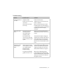
1
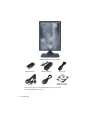
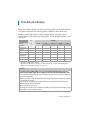
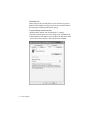
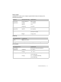
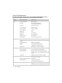
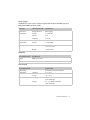
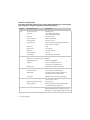
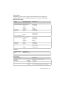
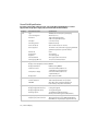
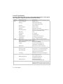
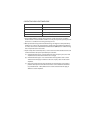
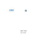
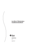
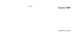
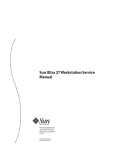
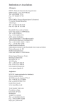
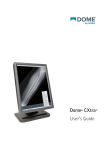
Dome® Ex Display
User’s Guide
© 2011 NDS Surgical Imaging. All rights reserved.
Information in this document has been carefully checked for accuracy; however, no
guarantee is given to the correctness of the contents. This document is subject to
change without notice. NDSsi provides this information as reference only. Reference
to products from other vendors does not imply any recommendation or
endorsement.
This document contains proprietary information protected by copyright. No part of
this manual may be reproduced by any mechanical, electronic, or other means, in
any form, without prior written permission of NDSsi.
NDS Surgical Imaging, NDSsi, the NDSsi logo, Dome, the Dome by NDSsi logo,
Dome E2, Dome E2cHB, Dome E3, Dome E3cHB, Dome E3cHB DisplayPort, Dome E5,
Dome CXtra, RightLight are either registered or unregistered trademarks of NDS
Surgical Imaging. All other trademarks are the property of their respective owners.
020-0902-00A
About the Display
The Dome® Ex display systems, ranging from 2 to 5 megapixels,
consists of a TFT LCD panel and a display board and driver. The
display’s thin film transistors, in a transmissive-type display, use an
integrated cold cathode fluorescent tube (CCFT) backlight system.
The display is designed for medical imaging in diagnostic settings, in
portrait or landscape orientation, and comes fully tuned with gamma
correction that complies with the DICOM Part 14 Standard. The alldigital design enables the display to produce the sharp, crisp images
critical to softcopy medical viewing. Unwanted analog display image
artifacts are eliminated.
Bundled with the display system, the Dome CXtra software enhances
the functionality of the Dome Ex display with a range of value-added
services, such as DICOM calibration, error reporting, and backlight
saver. Network management of Dome displays running the Dome
CXtra software requires the Enterprise Management Service for
Dome CXtra. For more information, refer to Dome CXtra User’s Guide.
AMLCD panel mounted on desk stand
Display controller
DVI cable
DC power adapter*
DisplayPort cable**
Power cords
Display driver and
calibration software
* Some Dome Ex displays ship with a DC adapter that operates per power switch.
** For Dome E3cHB DisplayPort unit only.
2 | Dome Ex Display
System Requirements
All display systems require operating system Windows 7 (x86 or x64)
or Windows XP Service Pack 3 (x86 or x64).
IMPORTANT! Note the following:
• NVIDIA boards. Display configurations using the NVS295 board
require a DisplayPort-to-DVI adapter. Display configurations, except
for the Dome E3cHB DisplayPort unit, using Quadro 600, Quadro 2000,
or Quadro 4000 require a DisplayPort-to-DVI adapter for the second
display.
• Ten-bit display systems. Graphics boards cannot be mixed on 10-bit
display systems. Use multiple boards of the same type.
Display
Controller
System Requirements
Dome E2
Dome E2cHB
NVS295*
Dome E2
Dome E2cHB
Dome E3
Dome E3cHB
Dome E3cHB DisplayPort
Dome E4c†
Dome E5
Quadro FX380 or • PCI Express x16 lane slot
Quadro 2000D
• 50 MB hard disk space
Dome E2
Dome E2cHB
Dome E3
Dome E3cHB DisplayPort
Dome E5
Quadro 600,
Quadro 2000, or
Quadro 4000
• Intel or AMD multi-core
processor
• 512 MB RAM
• CD-ROM drive
• Power supply, 350 watts or
greater
• Auxiliary power cable with
standard 6-pin connector
(for Quadro 4000 only)
* NVS295 board x1 or x16.
† Refer to Dome E4c Display User’s Guide for instructions.
About the Display | 3
Display Components
Review this illustration of the back panel to identify controls and
ports on the display unit. Also see “Connector Ports” on page 31.
Dome E2, Dome E2cHB,
Dome E3, and Dome E5
Dome E3cHB
Dome E3cHB DisplayPort
All Dome Ex displays include the following on the connector plate:
• Power input. Drives power to the display; 4-pin port on Dome E2,
8-pin port on Dome E2cHB, Dome E3, and Dome E5, either 6- or
8-pin port on Dome E3cHB, and 6-pin port on Dome E3cHB
DisplayPort.
• Video input. Drives the data to the display. All Dome Ex displays
have a standard DVI connector. The Dome E3cHB DisplayPort
unit also includes a DisplayPort connector port.
• Reset button. Restores the display configuration to default
setting.
• LED lights. Provides information on the status of the display.
NOTE: Usage of both the mini-B USB port on Dome E3cHB and the
USB-B port on Dome E3cHB DisplayPort to be defined at a future
time.
4 | Dome Ex Display
Installing the Display
Before you install the display controller, remove any graphics card and its driver from
your system. Also disable any onboard graphics capability on the motherboard.
Install your Dome display with one of the qualified graphics cards shown in the
following table. See the I/O bracket of the graphics card on “Qualified Graphics Cards”
on page 32.
NVS
QUADRO
DISPLAY
295*
FX 380
600†
2000†
2000D
4000†
Dome E2
9
9
9
9
9
9
9
9
9
9
9
9
9
9
9
9
9
9
9
9
9
9
9
9
9
9
9
9
Dome E2cHB
Dome E3
Dome E3cHB
Dome E3cHB
DisplayPort
Dome E4c‡
Dome E5
9
9
9
* DisplayPort-to-DVI adapter required.
† DisplayPort-to-DVI adapter required for second Dome Ex display, except Dome E3cHB DisplayPort.
‡ Refer to Dome E4c Display User’s Guide for instructions.
Warning
In locations where 240V outlets are used, connect the Dome Ex display only to a
center-tapped, 240V, single-phase supply (for Canada and the United States only).
If you leave the computer turned on, you could get an electric shock and cause damage to
the system components.
Remove the display controller slowly from its package and static-shielding bag to prevent
an electrostatic discharge.
Static electricity can damage the controller. When touching the board or parts of the
motherboard, take these precautions:
• Wear an antistatic wrist strap.
• Discharge your body’s static electricity repeatedly by touching the power supply or the
metal surface of the computer chassis.
Installing the Display | 5
Hardware Installation Tips
• NVIDIA boards. All boards referred to in this manual, except the
NVS295 board, support single link and dual link on DVI ports. The
NVS295 board supports single link only via DisplayPort-to-DVI
adapter.
• Multiple displays. Connect all displays to the video board before
you turn on the computer and install the driver.
• Access to ports. For displays mounted on a desk stand, rotate the
LCD panel from portrait to landscape for better access to the
ports.
• Threading cables. Thread the DVI cable and power cord through
the stand column. Make sure the cable and cord run through the
notches. To reattach the stand cover, align the hooks with the
slots on the stand. Press the cover into place. A click sound signals
a secure connection.
Installing the Display Controller
Before you install the display controller, choose a well-ventilated
location with an adequate amount of space. Excessive heat cannot
dissipate when display vents are blocked. Make sure a grounded AC
outlet is within easy reach.
Turn your computer off. Leave the power cord plugged into the
grounded outlet.
To install the display controller
1 Remove the computer cover.
2 Remove any existing graphics card and video signal cable.
3 Remove the blank bracket from an available PCI Express slot.
4 Insert the display controller into the slot, align the connector pins,
and press the board down until it is firmly seated.
5 For Quadro 4000 board only: Connect the 6-pin auxiliary power
supply cable to the controller. (Use the built-in 6-pin connector if it
is present.)
6 Secure the mounting bracket.
7 Reattach the computer cover and the peripherals.
6 | Dome Ex Display
NOTE: For installation of the Quadro 4000 board only. If your
computer lacks a built-in 6-pin connector from the power supply, you
need to use the adapter cable supplied with the display controller to
complete the installation of the board.
Connecting the Video and Power Cables
Turn your computer off. Leave the power cord plugged into
the grounded outlet. Use the Dome Ex display with the power
adapter and video cable shipped.
IMPORTANT! Note the following:
• Display configurations using the NVS295 board may require a
DisplayPort-to-DVI adapter.
• Display configurations using the Quadro 600, 2000, or 4000 board,
except for the Dome E3cHB DisplayPort unit, require a DisplayPortto-DVI adapter for the second display.
• For the Dome E3cHB DisplayPort unit only. Install either the DVI or
the DisplayPort video cable, not both.
To connect the cables
1 Plug one end of the video cable into the video port on the interface
plate. Secure the connection.
2 Plug the power cord into the power input port on the
interface plate.
3 Plug the other end of the video cable into the video port on the
installed display controller. (Use the bottom port of a single display
installation or for the first display of a multiple display setup.)
Secure the connection.
4 Plug the other end of the power cord into the power supply.
5 Repeat steps 1 to 4 to connect another display to the controller.
6 Plug the power supply cord(s) into a grounded AC outlet.
7 If you are using a BridgePower adapter, turn on the adapter power
switch before you turn on the computer.
Installing the Display | 7
Installing the Display Driver
Before you install the driver, remove any previously installed display
driver for the display controller from your system.
To install the driver
1 Start the system.
Note: On Windows XP, click Cancel on the Found New Hardware
Wizard.
2 Insert the driver installation CD and run Setup.exe.
3 Click Next.
4 Click Yes to the license agreement. The installation starts.
5 Follow the onscreen instructions to complete the installation. When
the Setup complete message appears, select Yes, I want to restart
my computer now. Click Finish.
6 If the Digital Signature Not Found message appears, click Yes or
Continue to complete the driver installation.
8 | Dome Ex Display
Adjusting the Display Properties
After installation, use the Display Properties dialog to makes changes
to the video settings or to set up a multiple display configuration.
For Windows 7
To set display properties
1 Right-click the desktop and select Personalize.
2 Click Display on the left panel of the dialog.
3 Click Adjust Resolution on the left panel.
4 Take one of these actions to view display assignments or change
the appearance of a display.
• Click Identify to view the order of display assignments.
• Click on a display in the illustrated configuration to select it.
• Pull down the Display box to view the name identification of a
display or to select it.
• Pull down the Resolution box to make changes to the
appearance of a selected display. (Also see page 30.)
• Select a display then click Advanced Settings if you wish to see
which graphics board is installed on the display system.
5 Click Apply or OK.
Display
Resolution
Orientation
Dome E2
Dome E2cHB
1200 x 1600
1600 x 1200
Portrait
Landscape
Dome E3
Dome E3cHB
Dome E3cHB DisplayPort
1536 x 2048
2048 x 1536
Portrait
Landscape
Dome E5
2048 x 2560
2560 x 2048
Portrait
Landscape
Installing the Display | 9
For Windows XP
Set the display mode manually if the correct resolution (e.g.,1536 x
2048 for Dome E3cHB) is missing from the Screen resolution field on
the Setting tab of the Display Properties dialog.
To set the display mode manually
1 Right-click the desktop and select Properties > Settings.
2 Select the monitor that you want to change. Then click Advanced.
3 Click the Monitor tab. Make sure the check box for Hide modes that
this monitor cannot display is empty (unchecked). Click OK.
10 | Dome Ex Display
4 Click the Adapter tab, then click the List All Modes button.
5 Choose the mode and click OK. Click OK to finish.
Display
Resolution
Orientation
Dome E2
Dome E2cHB
1200 x 1600
1600 x 1200
Portrait
Landscape
Dome E3
Dome E3cHB
Dome E3cHB DisplayPort
1536 x 2048
2048 x 1536
Portrait
Landscape
Dome E5
2048 x 2560
2560 x 2048
Portrait
Landscape
To set up a multiple display configuration
1 Right-click the desktop and select Properties > Settings.
2 Click the monitor icon for the inactive Dome display. Then select
Extend my Windows desktop onto this monitor.
3 Set the resolution and color quality of the display. (See page 30.)
4 Repeat steps 2 and 3 for each display you want to make active.
5 Click OK.
Setting Brightness
You must have the Dome CXtra software installed to change the
display brightness. Adjust the value of the white level on the
Backlight tab of the RightLight Panel Configuration dialog. Refer to
Dome CXtra User’s Guide for more information.
Installing the Display | 11
Power Management
You have two ways to lower energy usage when the Dome Ex display
is idle:
• Dome CXtra Backlight Saver service (preferred)
• Screen Saver (set via Windows operating system)
Activate the power saver when you anticipate periods of inactivity,
such as at the end of the work day. Once activated, Backlight Saver (or
Screen Saver) automatically turns the backlight off during the period
of inactivity. Backlight Saver and Screen Saver both extend the life of
the backlight and reduce burn-in of images.
Do not use the Backlight Saver and Screen Saver concurrently.
12 | Dome Ex Display
Technical Information
The design of the Dome® Ex digital display takes into account every
known measure to ensure your personal safety. Improper use of
the display can result in electric shock, fire, or damage to the display.
Read all instructions before setting up the display.
Classification:
Shock Protection: Class I.
Degree of Protection Against Electric Shock: No applied part.
Degree of Protection Against Harmful Ingress of Water:
Ordinary equipment (IPX0).
Degree of Safety in the Presence of Flammable Anaesthetic
Mixture with Air or with Oxygen or Nitrous Oxide:
Not suitable for use in the presence of a flammable
anaesthetic mixture with air or with oxygen or nitrous oxide.
Mode of Operation: Continuous.
Important recycle instruction:
HAZARDOUS SUBSTANCE. Lamp(s) inside this product contain
mercury. This product may contain other electronic waste
that can be hazardous if not disposed of properly. Recycle
or dispose in accordance with local, state, or federal laws.
For more information, contact the Electronic Industries
Alliance AT WWW.EIAE.ORG. For lamp-specific disposal
information, check WWW.LAMPRECYCLE.ORG.
DISPOSAL. Do not use household or municipal waste
collection services for disposal of electrical and electronic
equipment. EU countries require the use of separate
recycling collection services.
ENVIRONMENT-FRIENDLY USE PERIOD. Hazardous
substances are present. The number encircled by the
recycling symbol indicates the safe-use period (in years).
China requires the use of recycling services at the end of
product life.
Technical Information | 13
Symbol explanations
CAUTION. Read the accompanying text carefully, for
proper operation and maintenance of the display
system.
DANGEROUS VOLTAGE. Important precautions about
electric shock. Read the accompanying text carefully, to
prevent damage to display components and to guard
your safety.
DIRECT CURRENT.
BAROMETRIC PRESSURE. Transport and storage
12,000 meters (39,400 feet), maximum in unpressurized
container.
RELATIVE HUMIDITY. Transport and storage 5% to 90%
(noncondensing).
TEMPERATURE. Transport and storage -10° to 60° C.
Intended use
The Dome Ex display is an AMLCD display designed for viewing
medical X-ray images. This unit should not be used near patients and
should be kept outside of 1.83 m perimeter and 2.29 m vertical.
IMPORTANT: From the Dome Ex display series, only the Dome E5
display can be used for primary image diagnosis in mammography.
The Dome E2, Dome E2cHB, Dome E3, Dome E3cHB, and Dome E3cHB
DisplayPort units must not be used for primary image diagnosis in
mammography.
CAUTION: Federal law restricts this device to sale by or on the order of
a medical practitioner.
14 | Dome Ex Display
Safety precautions
External equipment intended for connection to signal input, signal
output, or other connectors, must comply with the relevant IEC standard
(EN/IEC 60601-1 series for medical electrical equipment). In addition, all
such combinations (systems) must comply with the standard IEC 60601-1-1,
Safety requirements for medical electrical systems.
Equipment not complying to IEC 60601 must be kept outside the patient
environment, as defined in the standard as at least 1.5 meters from the
patient or the patient support.
Any person who connects external equipment to signal input, signal output,
or other connectors has formed a system and is therefore responsible for the
system to comply with the requirements of IEC 60601-1-1. If in doubt, speak
with a qualified technician.
Safety tips
• Never open the display case, even when the power is off. Dangerous
voltage inside may cause electric shock or death.
• To avoid damage to the display, use the grounded power supply and
video cable supplied by NDSsi, or use certified replacements.
• Be sure the display is electrically grounded. You must connect the third
grounding pin on the US power cord to a grounded outlet. The European
power cord does not have a third grounding pin, but it must be plugged
into a grounded outlet.
• If you cannot insert the plug into the outlet you plan to use, have a
licensed electrician replace the outlet with a properly grounded outlet.
If the power cord connects directly into the computer, make sure the
computer is grounded.
• Keep the display dry if it is part of a surgical system. The display lacks
protection against liquids or spills.
• In locations where 240V outlets are used, connect the Dome Ex
display only to a center-tapped, 240V, single-phase supply (for
Canada and the United States).
GROUNDING RELIABILITY CAN ONLY BE ACHIEVED WHEN EQUIPMENT IS
CONNECTED TO AN EQUIVALENT RECEPTABLE MARKED “HOSPITAL ONLY” OR
“HOSPITAL GRADE.”
Technical Information | 15
Unpacking and handling tips
The Dome Ex display is a precision instrument that requires proper care to
maintain product operation and adherence to specification. Unpack the
display and components carefully, then set up and handle the unit properly
to avoid damage to the LCD panel.
• Use both hands to grasp the display case when lifting it from the shipping
carton, but avoid touching the screen.
• Do not apply pressure to the screen or touch the screen with bare fingers
or objects. Pressure can affect image quality. Cosmetics and oils on the skin
are both detrimental to the screen and difficult to remove.
• Allow the display to warm up to room temperature before turning it on.
Avoid sudden temperature changes in the environment, as this may cause
condensation, which damages the display.
• Secure the display properly onto a standard VESA 100-mm mounting unit if
you elect not to use the desk stand.
• Do not set up the display near strong light or heat sources.
• Do not block the vents on the back of the display or install the display in
a built-in enclosure. Blocked vents cause excessive heat to build up inside
the display, increasing risk of fire.
• When installing components, turn off your computer, but leave it plugged
into a grounded outlet.
• Do not remove the back cover or disassemble the display. There are
no user-serviceable parts inside.
Preventing fire and injury
• Replace the power supply or cables if damaged.
• Use only the power source indicated in this guide or listed on the display.
• Do not plug the power supply into an overloaded AC outlet or extension
cord. Overloaded AC outlets and cords can result in electric shock or fire.
• Do not drop or push objects into the display case. Internal components
contain high voltage.
• Unplug the power cord from the wall outlet during thunderstorms.
• Do not place magnetic devices, such as motors, near the display.
16 | Dome Ex Display
Cleaning the display
Observe the following guidelines to maintain the display and the LCD screen.
• Use a clean, lint-free, absorbent cotton cloth to clear off any residual glue
from removal of the protective film or to remove surface dust. Apply light
pressure to remove the dust.
• Dampen a clean cloth with a small amount of isopropyl alcohol to remove
glue or dust if the screen is still not clean. Do not saturate the cloth;
otherwise, alcohol may seep into the display case and collect in the
enclosure. Use a clean, dry cloth to completely remove the alcohol residue.
• Do not use chemically treated dust cloths, acetone, toluene, or harsh
solvents on the display case or the screen. They can damage the polarizer
and the display case.
• Do not expose the display to water or excessive moisture. Do not allow
water or other stains to stand on the unit. Wipe liquids off immediately to
prevent damage to the display case and the screen.
WARNING
DISCONNECT SUPPLY BEFORE SERVICING
AVERTISSEMENT
COUPER L’ALIMENTATION AVANT L’ENTRETIEN ET LE DEPANNAGE
Shipping/storing the display
Keep the display in its shipping container until installation. Return the display
to its original container whenever you need to store the unit, move it to
another location, or return it for repair. The packaging supplied by the
manufacturer protects the display while it is in transit. See environment
specifications for more information.
Before returning the display to the container, do the following:
1 Swivel the display panel to landscape mode.
2 Push the panel down to the lowest position.
3 Use the stand lock to anchor the panel.
Disposal information
Follow your local governing ordinance and recycling policy for
proper disposal or recycling of display components.
Technical Information | 17
Dome E2 Specification
In locations where 240V outlets are used, connect the Dome E2 display to a center-tapped,
240V, single-phase supply only (for Canada and the United States).
Category
Characteristic Item
Specification
Screen
Screen size diagonal
498 mm (19.6 in.)
Resolution
1200 x 1600 pixels (portrait)
1600 x 1200 pixels (landscape)
Pixel pitch
0.249 mm x 0.249 mm
Pixel arrangement
Subpixel vertical stripe
Interface
Input formats
Physical
Power
18 | Dome Ex Display
Active area (mm)
398.4 (H) x 298.8 (V)
Grayscale supported
3061 shades of gray
Refresh rate
60 Hz
Contrast ratio
850:1 (typical)
Brightness
1140 cd/m2 (typical)
Pixel rise/fall time
40 ms (typical)
Viewing angle
170° (± 85°) horizontal/vertical
Digital Video In
DVI Rev. 1.0 digital dual-channel connector
Display control - brightness/
contrast
DDC2B+
Display identification
EDID read using DDC2B+
USB hub
Universal Serial Bus (USB) Rev. 2.0:
1 uplink B port; 2 downlink A ports
Display status
Dual-stack tricolor LEDs on back panel
Landscape orientation
1600 x 1200 (8-bit and 24-bit per pixel)
Portrait orientation
1200 x 1600 (8-bit and 24-bit per pixel)
VGA to XGA/SXGA
640 x 480 to 1024 x 768 in both landscape and
portrait rotations, 1280 x 1024 displayed in
landscape rotation
Screen type
AMLCD (active matrix liquid crystal display)
Display size (without stand)
440 mm x 343 mm x 95 mm
(17.3 in. x 13.5 in. x 3.75 in.)
Display weight (without stand)
5.5 kg (12 lb)
Mounting options
Desktop stand (standard);
100-mm VESA mounting (optional)
Adapter, 4-pin power connector Ault MW116KA1249F53 (CAUTION: Use only the
power adapter supplied with the display unit.)
Power Supply
CAUTION: Use only the power adapter supplied with the Dome E2 display unit;
Ault MW116KA1249F53.
Category
Characteristic Item
Specification
Power input
requirements
Voltage selection
Auto-ranging
Voltage
100–240V AC
Current
1.0 A
Frequency
50–60 Hz
Power output
requirements
Voltage
12 V DC ±5%
Current
6.67 A (80 W)
Physical
Size
127.0 mm x 76.2 mm x 44.5 mm
(5 in x 3 in x 1.75 in)
Weight
0.7 kg (1.5 lb)
Reliability
Characteristic item
Specification
Display
MTBF 50,000 hours
Backlight
MTBF 50,000 hours to 50% brightness with backlight on continuously
Environment
Characteristic item
Specification
EMI shielding
Temperature
Humidity
No emission of low-level radiation
operating
0° C ~ 40° C
storage
-10° ~ 60° C
operating
10% ~ 80% Relative Humidity
(noncondensing)
storage
5% ~ 90% Relative Humidity
(noncondensing)
Technical Information | 19
Dome E2cHB Specification
In locations where 240V outlets are used, connect the Dome E2cHB display to a centertapped, 240V, single-phase supply only (for Canada and the United States).
Category
Characteristic Item
Specification
Screen
Screen size diagonal
498 mm (19.6 in.)
Resolution
1200 x 1600 pixels (portrait)
1600 x 1200 pixels (landscape)
Pixel pitch
0.249 mm x 0.249 mm
Interface
Input formats
Physical
Power
Pixel arrangement
RGB vertical stripe
Active area (mm)
398.4 (H) x 298.8 (V)
Colors supported
16.7 M
Refresh rate
60 Hz
Contrast ratio
700:1 (typical)
Brightness
800 cd/m2 (typical)
Pixel rise/fall time
40 ms (typical)
Viewing angle
170° (± 85°) horizontal/vertical
Digital Video In
DVI Rev. 1.0 digital dual-channel connector
Display control - brightness/
contrast
DDC2B+
Display identification
EDID read using DDC2B+
USB hub
Universal Serial Bus (USB) Rev. 2.0:
1 uplink B port; 2 downlink A ports
Display status
Dual-stack tricolor LEDs on back panel
Landscape orientation
1600 x 1200 (8-bit and 24-bit per pixel)
Portrait orientation
1200 x 1600 (8-bit and 24-bit per pixel)
VGA to XGA/UXGA
640 x 480 to 1024 x 768 in both landscape and
portrait rotations, 1280 x 1024 displayed in landscape
rotation
Screen type
AMLCD (active matrix liquid crystal display)
Display size (without stand)
440 mm x 343 mm x 95 mm
(17.3 in. x 13.5 in. x 3.75 in.)
Display weight (without stand)
5.5 kg (12 lb)
Mounting options
Desktop stand (standard);
100-mm VESA mounting (optional)
Adapter, 8-pin power connector BridgePower BPM130S12F02 (with power switch)
(CAUTION: Use only the adapter supplied with unit.)
20 | Dome Ex Display
Power Supply
CAUTION: Use only the power adapter supplied with the Dome E2cHB display unit;
BridgePower BPM130S12F02 (130W).
Category
Characteristic Item
Specification
Power input
requirements
Voltage selection
Auto-ranging
Voltage
100–240V AC
Current
3.0 A
Frequency
50–60 Hz
Power output
requirements
Voltage
12 V DC ±5%
Current
10.8 A (130W)
Physical
Size
228.6 mm x 76.2 mm x 50.8 mm
(9 in x 3 in x 2 in)
Weight
1.3 kg (2.75 lb)
Reliability
Characteristic item
Specification
Display
MTBF 50,000 hours
Backlight
MTBF 50,000 hours to 50% brightness with backlight on continuously
Environment
Characteristic item
Specification
EMI shielding
Temperature
Humidity
No emission of low-level radiation
operating
0° C ~ 50° C
storage
-20° ~ 60° C
operating
10% ~ 80% Relative Humidity
(noncondensing)
storage
5% ~ 90% Relative Humidity
(noncondensing)
Technical Information | 21
Dome E3 Specification
In locations where 240V outlets are used, connect the Dome E3 display to a center-tapped,
240V, single-phase supply only (for Canada and the United States).
Category
Characteristic Item
Specification
Screen
Screen size diagonal
528 mm (20.8 in.)
Resolution
1536 x 2048 pixels (portrait)
2048 x 1536 pixels (landscape)
Pixel pitch
0.207 mm, 123 ppi
Interface
Pixel arrangement
Subpixel vertical stripe
Active area (mm)
423.9 (H) x 318.0 (V)
Color supported
256 shades of gray, programmable gamma from
palette of up to 3061 shades
Refresh rate
60 Hz
Contrast ratio
900:1 (typical)
Brightness
1000 cd/m2 (typical)
Pixel rise/fall time
35–50 ms
Viewing angle
170° (± 85°) horizontal/vertical
Digital Video In
DVI Rev. 1.0 digital dual-channel connector
Display control - brightness/contrast DDC2B+
Input formats
Physical
Power
Display identification
EDID read using DDC2B+
USB hub
Universal Serial Bus (USB) Rev. 2.0:
1 uplink B port; 2 downlink A ports
Display status
Dual-stack tricolor LEDs on back panel
Landscape orientation
2048 x 1536 (8- and 24-bit per pixel)
Portrait orientation
1536 x 2048 (8- and 24-bit per pixel)
VGA to SXGA
640 x 480 to 1280 x 1024 pixels displayed in
both landscape and portrait rotations
Screen type
AMLCD (active-matrix liquid crystal display)
Display size (without stand)
475 mm x 368 mm x 96 mm
(18.7 in. x 14.5 in. x 4.0 in.)
Display weight (without stand)
6.35 kg (<15 lb)
Mounting options
Desktop stand with integrated USB (standard);
100-mm VESA mounting (optional)
Adapter, 8-pin power connector
Ault MW122RA1223F52 or Ault MW122KA1223F52
BridgePower BPM130S12F02 (with power switch)
(CAUTION: Use only the adapter supplied with unit.)
22 | Dome Ex Display
Power Supply
CAUTION: Use only the power adapter supplied with the Dome E3 display unit;
Ault MW122RA1223F52 or Ault MW122KA1223F52 (both 120W), or BridgePower
BPM130S12F02 (130W).
Category
Characteristic Item
Specification
Ault MW122RA1223F52 or Ault MW122KA1223F52
Power input requirements Voltage selection
Auto-ranging
Voltage
100–240V AC
Current
2.0 A
Frequency
50–60 Hz
Power output
requirements
Voltage
12 V DC ±5%
Current
10.0 A (120 W)
Physical
Size
228.6 mm x 76.2 mm x 50.8 mm
(9 in x 3 in x 2 in)
Weight
1.3 kg (2.75 lb)
BridgePower BPM130S12F02
Power input requirements Voltage selection
Auto-ranging
Voltage
100–240V AC
Current
3.0 A
Frequency
50–60 Hz
Power output
requirements
Voltage
12 V DC ±5%
Current
10.8 A (130W)
Physical
Size
228.6 mm x 76.2 mm x 50.8 mm
(9 in x 3 in x 2 in)
Weight
1.3 kg (2.75 lb)
Reliability
Characteristic item
Specification
Display
Backlight
MTBF >50,000 hours
MTBF 50,000 hours to 50% brightness with backlight on continuously
Environment
Characteristic item
EMI shielding
Temperature
Humidity
Specification
operating
storage
operating
storage
No emission of low-level radiation
0° C ~ 40° C
-10° ~ 60° C
10% ~ 80% Relative Humidity (noncondensing)
5% ~ 90% Relative Humidity (noncondensing)
Technical Information | 23
Dome E3cHB Specification
In locations where 240V outlets are used, connect the Dome E3cHB display to a centertapped, 240V, single-phase supply only (for Canada and the United States).
Category
Screen
Interface
Characteristic Item
Specification
Type
AMLCD (active-matrix liquid crystal display)
Screen size diagonal
540 mm (21.3 in.)
Resolution
1536 x 2048 pixels (portrait)
2048 x 1536 pixels (landscape)
Pixel pitch
0.211 mm, 120 dpi
Pixel arrangement
R,G,B vertical stripe
Active area (H x V)
433.2 x 324.9 mm (17.05 x 12.79 in.)
Color supported
16.7 million colors; 256 shades of gray (programmable
gamma from palette of up to 2041 shades)
Refresh rate
60 Hz
Contrast ratio
750:1 (typical)
Brightness
700 cd/m2 (typical)
Pixel rise/fall time
24 ms typical (14 ms Tr/10 ms Tf)
Viewing angle (CR 10: 1)
170° (± 85°) horizontal/vertical
Digital Video In
DVI Rev. 1.0 digital dual-channel connector
Display control (brightness/contrast) DDC2B+
Display identification
EDID read using DDC2B+
USB hub, on stand
Universal Serial Bus (USB) Rev. 2.0:
1 uplink B port; 2 downlink A ports
USB uplink, on display
Universal Serial Bus (USB) Rev. 2.0:
1 uplink mini-B port
Display status
Input formats Landscape orientation
Physical
Power
Dual-stack tricolor LEDs
2048 x 1536 (8 and 24-bit color per pixel)
Portrait orientation
1536 x 2048 (8 and 24-bit color per pixel)
VGA/XGA
640 x 480 to 1280 x 768 pixels (displayed in
both landscape and portrait orientations)
Display size (without stand)
475 mm x 369 mm x 102 mm (18.7 in. x 14.5 in. x 4.0 in.)
Display weight (without stand)
6.35 kg (15 lb) typical
Display weight (with stand)
10.2 kg (22.5 lb) typical
Mounting options
100-mm VESA compliant mounting;
Desktop stand with integrated USB (standard)
Adapter, 8-pin power connector
Adapter, 6-pin power connector
JEC Korea Corporation, Type JMW1150KA2423F51
JEC Korea Corporation, Type JMW1150KA2400F52
(CAUTION: Use only the adapter supplied with unit.)
24 | Dome Ex Display
Power Supply
CAUTION: Use only the power adapter supplied with the Dome E3cHB display unit.
Use JEC Korea Corporation, Type JMW1150KA2423F51 for displays with an 8-pin power
input connector. Use JEC Korea Corporation, Type JMW1150KA2400F52 for displays
with a 6-pin power input connector.
Category
Characteristic Item
Specification
Power input
requirements
Voltage selection
Auto-ranging
Voltage
100–240V AC
Current
3.0 A
Frequency
50–60 Hz
Power output
requirements
Voltage
24 V DC ±5%
Current
6.25 A (150 W)
Physical
Size
223.5 mm x 90.0 mm x 56.6 mm
(8.8 in x 3.5 in x 2.2 in)
Weight
1.4 kg (3 lb)
Reliability
Characteristic item
Specification
Display
MTBF 50,000 hours
Backlight
MTBF 50,000 hours to 50% brightness with backlight on continuously
Environment
Characteristic item
Specification
EMI shielding
Temperature
Humidity
No emission of low-level radiation
operating
0° C ~ 35° C
storage
-10° ~ 60° C
operating
8% ~ 80% Relative Humidity
(noncondensing)
storage
5% ~ 90% Relative Humidity
(noncondensing)
Technical Information | 25
Dome E3cHB DisplayPort Specification
In locations where 240V outlets are used, connect the Dome E3cHB DisplayPort unit to
a center-tapped, 240V, single-phase supply only (for Canada and the United States).
Category
Screen
Interface
Characteristic Item
Specification
Type
AMLCD (active-matrix liquid crystal display)
Screen size diagonal
540 mm (21.3 in.)
Resolution
1536 x 2048 pixels (portrait)
2048 x 1536 pixels (landscape)
Pixel pitch
0.2115 mm, 120 dpi
Pixel arrangement
R,G,B vertical stripe
Active area (H x V)
433.2 x 324.9 mm (17.05 x 12.79 in.)
Color supported
16.7 million colors; 256 shades of gray (programmable
gamma from palette of up to 2041 shades)
Refresh rate
60 Hz
Contrast ratio
750:1 typical
Brightness
700 cd/m2 typical
Pixel rise/fall time
24 ms typical (14 ms Tr/10 ms Tf)
Viewing angle (CR 10: 1)
170° (± 85°) horizontal/vertical
Digital Video In
DVI Rev. 1.0 digital dual-channel connector
DisplayPort Revision 1.1a connector
Display control (brightness/contrast) DDC2B+
Display identification
EDID read using DDC2B+
USB hub, on stand
Universal Serial Bus (USB) Rev. 2.0:
1 uplink B port; 2 downlink A ports
USB uplink, on display
Universal Serial Bus (USB) Rev. 2.0:
1 uplink B port
Display status
Input formats Landscape orientation
Physical
Power
Dual-stack tricolor LEDs
2048 x 1536 (8 and 24-bit color per pixel)
Portrait orientation
1536 x 2048 (8 and 24-bit color per pixel)
VGA/XGA
640 x 480 to 1280 x 768 pixels (displayed in
both landscape and portrait orientations)
Display size (without stand)
475 mm x 369 mm x 102 mm (18.7 in. x 14.5 in. x 4.0 in.)
Display weight (without stand)
6.35 kg (15 lb) typical
Display weight (with stand)
10.2 kg (22.5 lb) typical
Mounting options
100-mm VESA compliant mounting;
Desktop stand with integrated USB (standard)
Adapter
JEC Korea Corporation, Type JMW1150KA2400F52
(CAUTION: Use only the adapter supplied with unit.)
26 | Dome Ex Display
Power Supply
CAUTION: Use only the power adapter supplied with the Dome E3cHB DisplayPort unit.
Use JEC Korea Corporation, Type JMW1150KA2400F52.
Category
Characteristic Item
Specification
Power input
requirements
Voltage selection
Auto-ranging
Voltage
100–240V AC
Current
3.0 A
Frequency
50–60 Hz
Power output
requirements
Voltage
24 V DC ±5%
Current
6.25 A (150 W)
Physical
Size
223.5 mm x 90.0 mm x 56.6 mm
(8.8 in x 3.5 in x 2.2 in)
Weight
1.4 kg (3 lb)
Reliability
Characteristic item
Specification
Display
MTBF 50,000 hours
Backlight
MTBF 50,000 hours to 50% brightness with backlight on continuously
Environment
Characteristic item
Specification
EMI shielding
No emission of low-level radiation
Temperature
Humidity
operating
0° C ~ 35° C
storage
-10° ~ 60° C
operating
8% ~ 80% Relative Humidity
(noncondensing)
storage
5% ~ 90% Relative Humidity
(noncondensing)
Technical Information | 27
Dome E5 Specification
In locations where 240V outlets are used, connect the Dome E5 display to a center-tapped,
240V, single-phase supply only (for Canada and the United States).
Category
Screen
Interface
Input formats
Physical
Power
Characteristic Item
Specification
Screen size diagonal
541 mm (21.3 in.)
Resolution
2048 x 2560 pixels (portrait)
2560 x 2048 pixels (landscape)
Pixel pitch
0.165 x 0.165 mm
Pixel arrangement
LCR vertical stripe
Active area
422.40 (H) x 337.92 (V) mm
Grayscale supported
256 shades of gray, programmable gamma from
palette of up to 3061shades of gray
Refresh rate
50 Hz
Contrast ratio
800:1 (typical)
Brightness
750 cd/m2 (typical)
Pixel rise/fall time
50 ms typical (25 ms Tr/25 ms Tf)
Viewing angle
170° (± 85°) horizontal/vertical
Digital Video In
DVI Rev. 1.0 digital dual-channel connector
Display control - brightness/contrast
DDC2B+
Display identification
EDID read using DDC2B+
USB hub
Universal Serial Bus (USB) Rev. 2.0:
1 uplink B port; 2 downlink A ports
Display status
Dual-stack tricolor LEDs on back panel
Landscape orientation
2560 x 2048 (8-, 10-, and 24-bit gray per pixel)
Portrait orientation
2048 x 2560 (8-, 10-, and 24-bit gray per pixel)
VGA to XGA/SXGA
640 x 480 to 1024 x 768, displayed in both
landscape and portrait rotations
Screen type
AMLCD (active-matrix liquid crystal display)
Display size (without stand)
387 mm x 470 mm x 103 mm
(15.2 in. x 18.5 in. x 4.1 in.)
Display weight, typical
6.35 kg (14 lb) without stand
10.2 kg (22.5 lb) with stand
Mounting options
Desktop stand (standard);
100-mm VESA mounting (optional)
Adapter
Ault MW122RA1223F52 or Ault MW122KA1223F52
BridgePower BPM130S12F02 (with power switch)
(CAUTION: Use only the adapter supplied with unit.)
28 | Dome Ex Display
Power Supply
CAUTION: Use only the power adapter supplied with the Dome E5 display unit;
Ault MW122RA1223F52 or Ault MW122KA1223F52 (both 120W), or BridgePower
BPM130S12F02 (130W).
Category
Characteristic Item
Specification
Ault MW122RA1223F52 or Ault MW122KA1223F52
Power input requirements Voltage selection
Auto-ranging
Voltage
100–240V AC
Current
2.0 A
Frequency
50–60 Hz
Power output
requirements
Voltage
12 V DC ±5%
Current
10.0 A (120 W)
Physical
Size
228.6 mm x 76.2 mm x 50.8 mm
(9 in x 3 in x 2 in)
Weight
1.3 kg (2.75 lb)
BridgePower BPM130S12F02
Power input requirements Voltage selection
Auto-ranging
Voltage
100–240V AC
Current
3.0 A
Frequency
50–60 Hz
Power output
requirements
Voltage
12 V DC ±5%
Current
10.8 A (130W)
Physical
Size
228.6 mm x 76.2 mm x 50.8 mm
(9 in x 3 in x 2 in)
Weight
1.3 kg (2.75 lb)
Reliability
Characteristic item
Specification
Display
Backlight
MTBF >50,000 hours
MTBF 50,000 hours to 50% brightness with backlight on continuously
Environment
Characteristic item
EMI shielding
Temperature
Humidity
Specification
operating
storage
operating
storage
No emission of low-level radiation
0° C ~ 40° C
-10° ~ 60° C
10% ~ 80% Relative Humidity (noncondensing)
5% ~ 90% Relative Humidity (noncondensing)
Technical Information | 29
Video Modes
Resolutions expressed in pixels (W x H).
Display
Resolution
Orientation
Palette
Dome E2
1200 x 1600
1600 x 1200
Portrait
Landscape
Dynamic gray
Nonlinear gray
Static gray
8
Dome E2
Dome E2cHB
1200 x 1600
1600 x 1200
Portrait
Landscape
True color
32
Dome E3
1536 x 2048
2048 x 1536
Portrait
Landscape
Dynamic gray
Nonlinear gray
Static gray
8
Dome E3
Dome E3cHB
Dome E3cHB
DisplayPort
1536 x 2048
2048 x 1536
Portrait
Landscape
True color
32
Dome E5
2048 x 2560
2560 x 2048
Portrait
Landscape
Dynamic gray
Nonlinear gray
Static gray
8
30 | Dome Ex Display
Bits per pixel
Connector Ports
All Dome Ex displays have a standard DVI connector. The Dome E3cHB DisplayPort unit
also has a DisplayPort connector.
Display
Video
Port
DIN
Power
Connector Input
Adapter
Dome E2
DVI
4-pin
12V ±5%
(80 W)
Ault MW116KA1249F53
Dome E2cHB
DVI
8-pin
12V ±5%
(130 W)
BPC BPM130S12F02 (with
power switch)
Dome E3,
Dome E5
DVI
8-pin
12V ±5%
(120 W)
Ault MW122RA1223F52 or
Ault MW122KA1223F52
12V ±5%
(130 W)
BPC BPM130S12F02 (with
power switch)
24V ±5%
(150 W)
JEC JMW1150KA2400F52
(6-pin connector)
Dome E3cHB
DVI
6- or 8-pin
JEC JMW1150KA2423F51
(8-pin connector)
Dome E3cHB
DisplayPort
DVI and
DisplayPort
6-pin
24V ±5%
(150 W)
JEC JMW1150KA2400F52
Pin assignments for the 4-, 6-, and 8-pin power input ports.
VCC 1
2 GND
4-pin connector on Dome E2 display
GND 3
4 VCC
VCC 6
1 GND
VCC 5
2 GND
VCC 4
3 GND
VCC 8
VCC 7
1 GND
VCC 6
2 GND
VCC 5
6-pin connector on Dome E3cHB DisplayPort
and some Dome E3cHB displays
8-pin connector on Dome E2cHB, Dome E3,
Dome E5, and some Dome E3cHB displays
3 GND
4 GND
Technical Information | 31
Qualified Graphics Cards
For proper installation of the graphics card, use only the video cable(s) shipped with
your Dome display.
Graphics Card
NVS 295
2 DisplayPort (Single Link
DVI-D via DisplayPort to
DVI-D adapter)
Quadro FX 380
2 Dual Link DVI-I
Quadro 600
1 DisplayPort
1 Dual Link DVI-I
Quadro 2000
2 DisplayPort
1 Dual Link DVI-I
Quadro 2000D
2 Dual Link DVI-I
Quadro 4000
2 DisplayPort
1 Dual Link DVI-I
32 | Dome Ex Display
I/O Bracket
LED Status Lights
The two LEDs on the back panel of the Dome Ex displays provide
information about the display.
• LED A describes the digital-link status between the display
controller and the interface.
• LED B describes the display-panel status. it shows any faults
currently in the panel.
Reset button (left) and LEDs on interface plate
LED A, top
LED B
Technical Information | 33
Power-up sequence information from LED
LED A
Action/Sequence
LED B
Action/Sequence
Dark
Initial power-on
Flashing yellow
Initial power-on
Blink yellow
Self test
Solid yellow
Power-on self test
Dark
One (1) second after
power -on
Flashing green
Self test pass
LED A status information after initial power-on
LED Status
Description
Solid green
Functional link – normal operation
Flashing yellow
Link working, unrecognized sync information
LED B status information after initial power-on
LED Status
Description
Solid green
Functional system – normal operation
Flashing green
Fault
Solid yellow
DDC power-on, 12V/24V power not detected
Alternating green/yellow
POST failure
NOTE: A red LED or combination of red LEDs indicates a hardware or software fault.
Contact Dome Technical Support for assistance.
34 | Dome Ex Display
Troubleshooting
Problem
Possible Cause
Solution
No image appears on
the screen
Computer is OFF.
Power on the machine.
Power cord is not securely
connected.
Tighten power cord connection and
turn on computer.
Video cable connected
incorrectly.
Make sure the first display of a dualheaded system or the only display of
a single-headed system is connected to
the primary port on the display
controller.
A previous version of
the display driver is
still installed on the
computer system.
Remove any existing Dome display
driver before you install a more recent
version.
The installation CD
contains a file older than
the one currently on your
system.
The Confirm File Replace dialog box
appears if the installation CD contains
a file older than the one currently on
the system. Click No to the question,
Over-write the newer file? Or, click No
to All.
The function Hide all
modes that this monitor
cannot display is selected
on a subdialog of the
Windows Display
Properties dialog.
When using commodity graphics
boards with Dome Ex displays, make
sure the check box for the function is
empty (unchecked). See “To set the
display mode manually” on page 10.
A single-link commodity
graphics board is in use.
When using commodity graphics
boards with Dome E3, Dome E3cHB,
Dome E3cHB DisplayPort, and Dome E5
displays, be sure to install a DualLink
DVI graphics board.
Conflict with driver
version
Unable to set the
maximum or native
resolution of the
display
Technical Information | 35
Regulatory Compliance
Canada, European Union, United States
This display has been tested and found to comply with IEC/EN 60601-1 and
IEC/EN 60601-1-2 standards, and is certified to meet medical standard C22.2
No. 601.1-M90 (C US Mark).
The medical display, in
addition to meeting
medical requirements,
has been tested and
found to comply with the
limits for Federal
Dome E2, Dome E2cHB, Dome E3, Dome E3cHB,
Communications
Dome E3cHB DisplayPort, and Dome E5
Commission (FCC) Class B
computing devices in a
typically configured system since many medical offices are located in
residential areas. (This applies to all Dome Ex displays except the
Dome E3cHB, Dome E3cHB DisplayPort, and Dome E5 displays, which are
Class A.) It is the system integrator’s responsibility to test and ensure that
the entire system complies with applicable electromagnetic compatibility
(EMC) laws.
Warning on Dome E3cHB, Dome E3cHB DisplayPort, and Dome E5
The Dome E3cHB, Dome E3cHB DisplayPort, and Dome E5 displays are
Class A products. In a domestic environment, either of these products may
cause radio interference, in which case the user may be required to take
adequate measures.
Radio transmitting equipment, cellular phones, etc. shall not be used in
close proximity of the devices, since this could influence the performance
of the device.
Particular precaution must be considered during use of strong emission
sources, such as High Frequency surgical equipment and similar, so that,
for example, the HF-cables are not routed on or near the devices. If in
doubt, contact a qualified technician or your local representative.
We offer state-of-the-art displays suitable to the European market, CE-marked
displays based on compliance with counsel directive 93/42/EEC—commonly
referred to as the Medical Device Directive (MDD). The following summarizes
our qualification of these displays as it relates to compliance with the MDD.
The European Medical Device Directive requires that the intended use of
the device be defined. The intended use of these displays is “to display
alphanumeric, graphic, and image data as inputted from any type of medical
device.” These displays do not provide a measurement function in any way,
and it is the device and systems manufacturer’s responsibility to verify its
function in the integrated device or system.
The display was classified as required by the MDD according to Annex IX of
the directive and the medical device (MEDDEV) guidance available at the
time of classification. Because the display uses electrical energy and has
no direct patient connections and—by itself—no medical utility, the display
is classified according to Rule 12 as an MDD Class I device, component, or
accessory. The MDD states that manufacturers of Class I medical devices
or accessories shall satisfy the requirements in regard to design and
manufacturing controls, that is, the applicable assessment route to be used
for CE-marking under the MDD, and it shall carry the CE mark according to
Annex XII of the directive, with no notified body annotation.
The applicable safety standards for an MDD Class I display are EN 606011:1990 along with A1:1993, A12:1993, A2:1995, and A13:1996, as well as IEC
60601-1:1988 along with A1:1991 and A2:1995. To help the medical device
designer evaluate the suitability of these displays, NDSsi has also conducted
EMC testing to IEC 60601-1-2 as it can be applied. The display with its power
supply alone does not represent a functional medical device. Hence, NDSsi
configured a minimal operating system to exercise the display. The resulting
data are made available to interested parties.
This is informative data, not certification data. Certification data must be
obtained by the device or system integrator according to Article 12 of
the MDD titled “Particular procedure for systems and procedure packs.”
Paragraph 2 clearly outlines the device or system integrator’s responsibility
in this matter.
In summary, NDS Surgical Imaging is CE-marking these displays under the
Medical Device Directive, which establishes compliance to the basic medical
safety standards. However, EMC compliance can only be accomplished in the
configured medical device or system and is the responsibility of the device or
system manufacturer. NDSsi has the necessary documentation such as IEC
60601-1 notified body and other third-party test reports and certifications,
a risk/hazard analysis, an essential requirements checklist, and the NDS
Surgical Imaging International Electrotechnical Commission (IEC) declaration
of conformity.
NDS Surgical Imaging, located in San Jose, Calif., USA, is the manufacturer of
these displays in the meaning of the directive. As required by the MDD in
Article 14, NDS Surgical Imaging, not residing in the European Economic
Area (EEA), has a European representative, NDS Surgical Imaging —
Nijverheidscentrum 28, 2761 JP Zevenhuizen, The Netherlands (phone
+31-180-63-43-56; fax +31-180-63-21-91).
In the opinion of NDS Surgical Imaging registration required to put this
device into commerce is the responsibility of the medical device/system
manufacturer, and NDS Surgical Imaging supports this requirement by
providing a European Commission (EC) declaration of conformity. If NDS
Surgical Imaging supplies a display to an end user, rather than a device
manufacturer, it is the end user’s responsibility to ensure continued
compliance with the MDD of the system in which the display is integrated.
The supplier will make available on request, circuit diagrams, component part
lists, etc.
For vigilance reporting as required under Article 10 of the MDD, NDS Surgical
Imaging will provide any information requested by competent authority to
support any reported incident investigation by such an authority.
EU Declaration of Conformity for Medical Application
A Declaration of Conformity has been filed for this product. For additional
copies of the Declaration of Conformity document, contact NDS Surgical
Imaging.
The Dome Ex digital flat-panel display meets the essential health and safety
requirements, is in conformity with, and the CE marking has been applied
according to the relevant EU Directives listed below, using the relevant
section of the following EU standards and other normative documents;
EU EMC Directive 2004/108/EC
EU Electromagnetic Compatibility Directive
EN 60601-1-2 Medical
Electrical Equipment
Section 1.2. Collateral standard
electromagnetic compatibility requirements
EN 55011
Limits and methods of measurements for radio
interference characteristics of industrial,
scientific, and medical equipment
IEC 1000-3-2
Harmonic emissions
IEC 1000-3-3
Voltage fluctuations/flicker emissions
IEC 1000-4-2
Electrostatic discharge requirements for
industrial process measurement and control
equipment
IEC 1000-4-3
Radiated electromagnetic field requirements
for industrial process measurement and
control equipment
IEC 1000-4-4
Electrically fast transients for industrial process
measurement and control equipment
IEC 1000-4-5
Surge requirements
IEC 1000-4-11
Voltage variations/dips/interrupts
IEC 1000-4-6
Conducted immunity
IEC 1000-4-8
Magnetic field immunity
Conformance to the Medical Device Directive
93/42/EEC
EN 60601-1 Medical
Electrical Equipment
Part 1: General requirements for safety
U.S. FCC Compliance Statement
Class B Digital Device: Dome E2, Dome E2cHB, or Dome E3 Display
This device complies with Part 15 of the FCC Rules.
Operation is subject to the following two conditions:
(1) This device may not cause harmful interference, and
(2) this device must accept any interference received, including
interference that may cause undesired operation.
NOTE: This equipment has been tested and found to comply with the limits
for a Class B digital device, pursuant to Part 15 of the FCC Rules. These limits
are designed to provide reasonable protection against harmful interference
in a residential installation. This equipment generates, uses, and can radiate
radio frequency energy and, if not installed and used in accordance with the
instruction, may cause harmful interference to radio communications.
However, there is no guarantee that interference will not occur in a particular
installation. If this equipment does cause harmful interference to radio or
television reception, which can be determined by turning the equipment off
and on, the user is encouraged to try to correct the interference by one or
more of the following measures:
• Reorient or relocate the receiving antenna.
• Increase the separation between the equipment and receiver.
• Connect the equipment into an outlet on a circuit different from that to
which the receiver is connected.
• Consult the dealer or an experienced radio/TV technical for help.
Changes or modifications not expressly approved by the party
responsible for compliance could void the user’s authority to operate
the equipment under FCC rules.
Class A Digital Device: Dome E3cHB, Dome E3cHB DisplayPort, or
Dome E5 Display
This device complies with Part 15 of the FCC Rules.
NOTE: This equipment has been tested and found to comply with the limits
for a Class A digital device, pursuant to Part 15 of the FCC Rules. These limits
are designed to provide reasonable protection against harmful interference
when the equipment is operated in a commercial environment.
This equipment generates, uses, and can radiate radio frequency energy and,
if not installed and used in accordance with the instruction manual, may
cause harmful interference to radio communications.
Operation of this equipment in a residential area is likely to cause harmful
interference in which case the user will be required to correct the interference
at his own expense.
Changes or modifications not expressly approved by the party
responsible for compliance could void the user’s authority to operate
the equipment under FCC rules.
Each Dome Ex display has one or more of the following certifications.
China
China Compulsory Certification regulating safety and
EMC.
GB4943-2001
GB9254-2008
CB17625.1-2003
Class A
Dome E3cHB, Dome E3cHB DisplayPort, and Dome E5
Germany
TÜV Rheinland GM Mark for medical products.
Japan
Voluntary Control Council for Interference by
information technology equipment sold in Japan.
Class A
Dome E3cHB, Dome E3cHB DisplayPort, and Dome E5
Class B
Dome E2, Dome E2cHB, and Dome E3
Korea
Korea Certification.
NDSsi Dome® Display Products
Warranty and Service Terms and Conditions
STANDARD LIMITED WARRANTY
COVERAGE: NDS Surgical Imaging, LLC (hereinafter "NDSsi") warrants this product to be
in compliance with the specifications provided by NDSsi and to be free from defects in
material and workmanship as defined in such specifications. Subject to the conditions
set forth below, NDSsi agrees to repair or replace any defective part of the enclosed
unit for the length of period indicated on the chart below.
NDSSI PRODUCT
STANDARD WARRANTY COVERAGE
Dome® E Series
Radiology Displays
• Standard 5-year “repair and return” warranty
• Industry-leading 10-year backlight warranty on
grayscale displays*
• Industry-leading 5-year backlight warranty on
color displays† ‡
Dome® S Series
Radiology Displays
• Standard 5-year “repair and return” warranty
• Industry-leading 10-year backlight warranty on
grayscale displays
• Industry-leading 5-year backlight warranty on
color displays
Dome® GX2MP Display
Standard 3-year “repair and return” warranty
* If, within 10 years of initial purchase, the maximum output of the Dome Ex/Sx grayscale display is
determined by NDSsi to be less than 300 cd/m², NDSsi will repair or replace the display at its sole
discretion. The displays must have been run at or below the CXtra default brightness setting as configured
from the factory.
† If, within 5 years of initial purchase, the maximum output of the Dome Ex/Sx color display (excluding
the Dome E4c) is determined by NDSsi to be less than 250 cd/m², NDSsi will repair or replace the display at
its sole discretion. The displays must have been run in native color mode at or below the CXtra default
brightness setting as configured from the factory.
‡ If, within 5 years of initial purchase, the maximum output of the Dome E4c color display is
determined by NDSsi to be less than175 cd/m², NDSsi will repair or replace the display at its sole
discretion. The displays must have been run in native color mode at or below the CXtra default brightness
setting as configured from the factory
EXCLUSIONS – WHAT IS NOT COVERED
1 Any product with a defaced, modified, or removed serial number.
2 Damage, deterioration or a malfunction resulting from accident, misuse, neglect, fire,
water, lightning, or other acts of nature, unauthorized product modification, or
failure to follow instructions supplied with the product.
3 Cosmetic damage including, but not limited to: scratches, cracks, dents, markings,
glue and adhesive residue.
4 Any damage of the product due to shipment.
5 Any damage caused by factors external to the product, such as electric power
fluctuation or failure.
6 Normal wear and tear, including backlights dimming over time, or image retention
resulting from displaying fixed images for long periods of time.
7 Removal, installation, and set-up service charges.
8 Failures not reported within the warranty term.
9 Any NDSsi products purchased through a distributor, reseller, or medical device
manufacturer other than NDSsi (each, an “Intermediary”), where such Intermediary
provides direct warranty service to its end-user customers in connection with such
product.*
DISCLAIMER
This limited product warranty sets forth your sole and exclusive remedy and NDSsi’s
sole and exclusive liability under the Standard Limited Warranty described herein.
THERE ARE NO WARRANTIES, EXPRESS OR IMPLIED, WHICH EXTEND BEYOND THE
DESCRIPTION CONTAINED HEREIN INCLUDING, BUT NOT LIMITED TO, THE IMPLIED
WARRANTY OF MERCHANTABILITY, FITNESS FOR A PARTICULAR PURPOSE, OR
NONINFRINGEMENT.
* Note that NDSsi sells its products through distributors, resellers, and other medical
device manufacturers which prefer to provide their end-user customers with direct warranty
support. Contact NDSsi Customer Care to determine if the product that you purchased is
covered by this Standard Limited Warranty or whether you need to contact the Intermediary
through which you purchased the product for warranty service.
NDSSI’S LIABILITY IS LIMITED TO THE COST OF REPAIR OR REPLACEMENT OF THE
PRODUCT. NDSSI SHALL NOT BE LIABLE FOR THE FOLLOWING:
1 DAMAGE TO OTHER PROPERTY CAUSED BY ANY DEFECTS IN THE PRODUCT,
DAMAGES BASED UPON INCONVENIENCE, LOSS OF USE OF THE PRODUCT, LOSS OF
TIME, LOSS OF PROFITS, LOSS OF BUSINESS OPPORTUNITY, LOSS OF GOODWILL,
INTERFERENCE WITH BUSINESS RELATIONSHIPS, OR OTHER COMMERCIAL LOSS,
EVEN IF ADVISED OF THE POSSIBILITY OF SUCH DAMAGES.
2 ANY OTHER DAMAGES, WHETHER INCIDENTAL, INDIRECT, CONSEQUENTIAL OR
OTHERWISE.
3 ANY CLAIM AGAINST THE CUSTOMER BY A THIRD PARTY.
End-users are cautioned that system configuration, software, the application, customer
data and operator control of the system, among other factors, affect the product
performance. While NDSsi products are considered to be compatible with many
systems, specific functional implementation by the customers of the product may vary.
Therefore, suitability of a product for a specific purpose or application must be
determined by consumer and is not warranted by NDSsi.
This warranty gives you specific legal rights. You may have other rights, which may vary
from locality to locality. Some localities do not allow limitations on implied warranties
and/or do not allow the exclusion of incidental or consequential damages, so the
above limitations might not apply to you.
WARRANTY SERVICE - REPAIR & RETURN – (US AND CANADA ONLY)
• Our standard warranty service is “Repair and Return”. Repair and Return requires the
defective unit to be returned to our service location for repair.
• Our service location will repair your unit within ten (10) business days. The service
time-period does not include in-transit shipping time to or from our service location.
• Cost of shipment of the defective unit to NDSsi is the responsibility of the customer.
Cost of shipment of the repaired unit to Customer is the responsibility of NDSsi
(duties and taxes to Canada are not included).
• NDSsi reserves the right in its sole discretion to provide Customer with a comparable
refurbished replacement unit in lieu of repair of customer’s defective unit.
• If NDSsi is unable within a reasonable time to repair or replace the defective unit, it
shall refund the purchase price for the product paid by the customer (exclusive of
taxes, installation and shipping related fees).
CONTACTING NDSSI CUSTOMER CARE
PRODUCT LINE
Dome®
TOLL FREE
(866) 961-9340
LOCAL
(503) 620-3787
E-MAIL
[email protected]
HOURS
6 A.M. – 5 P.M. Mon –Fri Pacific Time
1 Contact NDSsi Medical Support during the hours listed above. Have your NDSsi
model number and serial number available. You may be required to provide proof of
purchase as a condition for receiving warranty service.
2 Our representative may perform troubleshooting and diagnosis of the problem by
telephone or e-mail. If our representative is unable to fix the problem by telephone
or e-mail, we will issue a Return Material Authorization (RMA) for the nonfunctioning
unit and provide return instructions.
3 Upon receipt of the returned product, a service technician will evaluate the unit and
confirm the failure description provided by the customer.
(a) If the found failure type is covered under warranty, the repair, parts, labor and
shipment back to the customer will be at no charge.
(b) If the found failure type is not covered under warranty, NDSsi’s then current
evaluation fee will apply in addition to the cost of parts, labor and the return
shipment.
(c) If the unit is within the warranty period but the customer does not provide a
problem description and the service technician cannot determine the failure
(no problem found – “NPF”) NDSsi’s then current evaluation fee will apply in
addition to return shipment.
PAYMENT FOR NONWARRANTY EVALUATIONS AND REPAIRS AND OTHER EVALUATION
CHARGES: Nonwarranty repairs requested by customer will be performed at NDSsi’s
then current rates for any nonwarranty repairs and will include applicable evaluation
fees and the cost of return shipping (if customer requests that NDSsi ship the repaired
product). NDSsi further reserves the right in its sole discretion to request pre-payment
for any nonwarranty repairs, NPF evaluations, and return shipping charges prior to
return of the product to customer. Any invoiced amount not paid when due shall be
subject to a service charge equal to the lesser of one and one-half percent (1.5%) per
month or the maximum rate permitted by law. If NDSsi undertakes collection or
enforcement efforts, customer shall be liable for all costs thereof, including attorney’s
fees. NDSsi reserves the right to suspend warranty coverage to any customer who is in
default of payment until such payment has been made.
NDS Surgical Imaging, LLC
5750 Hellyer Avenue
San Jose CA 95138-1000 USA
www.ndssi.com