1
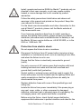
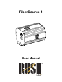
FiberSource 1 User Manual © 2015 Martin Professional ApS. Information subject to change without notice. Martin Professional and all affiliated companies disclaim liability for any injury, damage, direct or indirect loss, consequential or economic loss or any other loss occasioned by the use of, inability to use or reliance on the information contained in this manual. The Martin logo, the RUSH logo, the RUSH name, the Martin name and all other trademarks in this document pertaining to services or products by Martin Professional or its affiliates and subsidiaries are trademarks owned or licensed by Martin Professional or its affiliates or subsidiaries. Martin Professional • Olof Palmes Allé 18 • 8200 Aarhus N • Denmark • www.martin.com Manual: Revision A Table of contents Safety information ........................................................................... 4 Introduction ..................................................................................... 9 Before using the product ............................................................ 9 Fixture overview ............................................................................ 10 Physical installation ....................................................................... 11 Fastening the fixture to a flat surface ....................................... 11 Mounting the fixture on a truss................................................. 11 Securing with a safety cable .................................................... 12 AC power ...................................................................................... 13 Linking fixtures to power in a chain .......................................... 14 Fiber Optic Cable .......................................................................... 14 Cable connection ..................................................................... 14 Controller operation....................................................................... 15 Control data link ....................................................................... 15 Connecting the DMX data link ................................................. 16 DMX address ........................................................................... 16 Effects ...................................................................................... 19 Stand-alone operation ................................................................... 20 Setting stand-alone behavior ................................................... 20 Stand-alone and master settings table .................................... 21 Master/slave operation .................................................................. 22 Connecting fixtures for master/slave operation ....................... 22 Setting master/slave mode behavior ....................................... 22 Setting slave fixtures ................................................................ 23 Maintenance .................................................................................. 24 Cleaning ................................................................................... 24 Replacing the primary fuse ...................................................... 25 Installing or changing color filters ............................................ 25 Removing or installing the twinkle wheel section..................... 26 Installing a CTC filter ................................................................ 27 Service and repairs .................................................................. 27 Troubleshooting ............................................................................ 28 DMX protocol ................................................................................ 29 Specifications ................................................................................ 30 Safety information WARNING! Read the safety precautions in this manual before installing, operating or servicing this product. The following symbols are used to identify important safety information on the product and in this manual: Warning! Warning! Warning! Warning! Warning! Safety hazard. Risk of severe injury or death. Powerful light emission. Risk of eye injury. See user manual for important safety information. Hazardous voltage. Risk of lethal or severe electric shock. Hot surfaces and fire hazard. Warning! Risk Group 2 product according to EN 62471. Possibly hazardous radiation emitted from this product. May be harmful to the eyes. Do not stare at operating lamp and do not view the light output with optical instruments or any device that may concentrate the beam. This lighting fixture is for professional use only – it is not for household use. The fixture must be installed by a qualified technician. The safety of the installation is the responsibility of the installer. The fixture presents risks of severe injury or death due to fire hazards, electric shock, and falls. It produces a powerful, concentrated beam of light that can create a fire hazard or a risk of eye injury if the safety precautions below are not followed. Respect all locally applicable laws, codes and regulations when installing, operating or servicing the lighting fixture. 4 RUSH FiberSource 1™ User Manual Install, operate and service RUSH by Martin™ products only as directed in their user manuals, or you may create a safety hazard or cause damage that is not covered by product warranties. Follow the safety precautions listed below and observe all warnings in this manual and printed on the product. Keep this user manual for future use. For the latest user documentation and other information for this and all Martin™ products, please visit the Martin website at http://www.martin.com If you have any questions about how to install, operate or service the lighting fixture safely, please contact your Martin distributor (see www.martin.com/distributors for details) or call the Martin 24-hour service hotline on +45 8740 0000, or in the USA on 1-888-tech-180. Protection from electric shock Do not expose the fixture to rain or moisture. Disconnect the fixture from AC power before carrying out any installation or maintenance work, such as inserting a color filter, and when the fixture is not in use. Ensure that the fixture is electrically connected to ground (earth). Use only a source of AC mains power that complies with local building and electrical codes and has both overload and ground-fault (earth-fault) protection. Socket outlets or external power switches used to supply the fixture with power must be located near the lighting fixture and easily accessible so that the lighting fixture can easily be disconnected from power. Replace defective fuses with ones of the specified type and rating only. Isolate the fixture from power immediately if the power plug or any seal, cover, cable, or other component is damaged, defective, deformed, wet or showing signs of overheating. Do not reapply power until repairs have been completed. Before using the fixture, check that all power distribution equipment and cables are in perfect condition and rated for the RUSH FiberSource 1™ User Manual 5 electrical requirements of all connected devices. Use only Neutrik PowerCon cable connectors to connect to the fixture’s power sockets. Do not connect devices to power in a chain that will exceed the electrical ratings of any cable or connector used in the chain. The supplied power input cable is rated 6 A and can safely supply only one fixture with mains power. Do not connect any device to the fixture’s MAINS OUT connector when using this cable. If you replace this cable and also use the replacement cable to supply only one fixture with mains power, the replacement cable must also be rated 6 A minimum, have three conductors 18 AWG or 0.75 mm² minimum conductor size, have an outer cable diameter of 6 - 15 mm (0.2 - 0.6 in.) and be temperature-rated to suit the application. In the USA and Canada the cable must be UL listed, type SJT or equivalent. In the EU the cable must be type H05VV-F or equivalent. To connect fixtures to mains power in a chain, you must first obtain 14 AWG or 1.5 mm2 power input and throughput cables that are 16 A rated and temperature-rated to suit the application. In the USA and Canada the cables must be ULlisted, type SJT or equivalent. In the EU the cables must be type H05VV-F or equivalent. Suitable cables with Neutrik PowerCon connectors are available from Martin™ (see ‘Accessories’ on page 32). If you use these cables, you can connect fixtures to power in a linked chain, MAINS OUT throughput socket to MAINS IN input socket, but do not link more than fifteen (15) RUSH FiberSource 1 fixtures in total. The voltage and frequency at the MAINS OUT socket are the same as the voltage and frequency applied to the MAINS IN socket. Only connect devices to the MAINS OUT socket that accept this voltage and frequency. Protection from burns and fire Do not use the fixture to illuminate surfaces within 0.2 m (8 in.) of the fixture. Do not operate the fixture if the ambient temperature (Ta) exceeds 40° C (104° F). The surface of the product casing can reach up to 46° C (115° F) during operation. Avoid contact by persons and materials. Allow the fixture to cool for at least 60 minutes before handling. 6 RUSH FiberSource 1™ User Manual Keep flammable materials well away from the fixture. Keep all combustible materials (e.g. fabric, wood, paper) at least 0.1 m (4 in.) away from the fixture. Ensure that there is free and unobstructed airflow around the fixture. Provide a minimum clearance of 0.1 m (4 in.) around fans and air vents. Do not attempt to bypass thermostatic switches or fuses. Do not stick filters, masks or other materials onto any optical component. Protection from eye injury The light from the LED lamp is possibly hazardous and may be harmful to the eyes. Do not stare directly at operating lamp. Operate only as intended with a fiber optic cable inserted in the fiber optic port. Do not look at the light output with magnifiers, telescopes, binoculars or similar optical instruments that may concentrate the light output. Ensure that persons are not looking directly into the LEDs when the product lights up suddenly. This can happen when power is applied or when the product receives a DMX signal. To minimize the risk of eye irritation or injury, disconnect the fixture from power at all times when the fixture is not in use, and provide well-lit conditions to reduce the pupil diameter of anyone working on or near the fixture. Protection from injury Fasten the fixture securely to a fixed surface or structure when in use. The fixture is not portable when installed. Ensure that any supporting structure and/or hardware used can hold at least 10 times the weight of all the devices they support. If suspending from a rigging structure, fasten the fixture with two rigging clamps. Do not use safety cables as the primary means of support. Install as directed in this manual a secondary attachment such as a safety cable that will hold the fixture if a primary attachment fails. The secondary attachment must be approved by an official body such as TÜV as a safety attachment for the weight that it secures, must comply with RUSH FiberSource 1™ User Manual 7 EN 60598-2-17 Section 17.6.6 and must be capable of bearing a static suspended load that is ten times the weight of the fixture and all installed accessories. Check that all external covers, rigging hardware, and the fiber optic cable are securely fastened. Block access below the work area and work from a stable platform whenever installing, servicing or moving the fixture. In the event of an operating problem, stop using the fixture immediately and disconnect it from power. Never attempt to use a fixture that is obviously damaged. Do not modify the fixture or install other than genuine RUSH by Martin™ parts. 8 RUSH FiberSource 1™ User Manual Introduction The RUSH FiberSource 1™ is a powerful tool for illuminating fiber optic cables in permanent installations. With a 78 W LED light source, the RUSH FiberSource 1™ boasts improved efficiency and reliability while retaining all the key features of its popular predecessor. It provides nine interchangeable colors, twinkle effect, electronic dimming, a slot for a color temperature correction (CTC) filter, and DMX, stand-alone, and master/slave control options. Congratulations on your purchase of this RUSH by Martin™ lighting fixture. Details of the full range of Martin products are available on our website at www.martin.com. The RUSH FiberSource 1™ is supplied with this user manual, a 1.5 m (5 ft.) power cable (local power plug not included), four color filters, and a 19 mm (3/4 in.) fiber optic cable adaptor. Before using the product 1. Read ‘Safety information’ on page 4 before installing, operating or servicing the lighting fixture. 2. Unpack and ensure that there is no transportation damage before using the lighting fixture. Do not attempt to operate a damaged lighting fixture. 3. If the lighting fixture is not going to be hard-wired to a mains supply, install as directed in this manual a local power plug (not supplied) on the supplied power cable as described on page 13. 4. Install the provided fiber optic cable adaptor on one end of the cable. Insert and lock the adaptor in the fiber optic port. 5. Before operating, ensure that the voltage and frequency of the power supply match the power requirements of the lighting fixture. 6. Check the RUSH™ support pages on the Martin Professional™ website at www.martin.com for the most recent user documentation and technical information about the lighting fixture. RUSH by Martin™ user manual revisions are identified by the revision letter at the bottom of the inside cover. RUSH FiberSource 1™ User Manual 9 Fixture overview 10 1 Adaptor set screw 6 Access panel 11 Power LED 2 Fiber optic port 7 Safety eyebolt 12 DIP-switch 3 Screw mounting points 8 AC mains out 13 DMX LED 4 Clamp mounting points 9 AC mains in 14 Data in/out 5 Access panel screws 10 Fuse holder RUSH FiberSource 1™ User Manual Physical installation Read ‘Safety information’ on page 4 before installing the fixture. The fixture is designed for indoor use only and must be used in a dry location with adequate ventilation. Ensure that the fixture’s fan and ventilation slots are not blocked. Install at least 0.1 meters (4 in.) away from combustible materials (e.g. fabric, wood, paper) and well away from flammable materials. Fasten the fixture to a secure structure or surface. Do not stand it on a surface or leave it where it can be moved or fall over. If clamp mounting, secure it as directed in this user manual using a securely anchored safety cable that will hold the fixture if the primary fastening method fails. Martin™ can supply safety cables and rigging clamps that are suitable for use with the fixture (see ‘Accessories’ on page 32 ). Fastening the fixture to a flat surface The fixture can be permanently installed with a minimum of four fasteners (screws or bolts) to a hard, stable, flat surface that is oriented at any angle. Ensure that the surface can support at least 10 times the weight of all fixtures and equipment to be installed on it. Fasten through the grommets in the screw-mount points on the base flange using four suitable fasteners 5 mm (3/16 in.) in diameter and four 10 mm (3/8 in.) metal fender washers. Place the washers on the fasteners before inserting the fasteners through the mounting holes. Mounting the fixture on a truss The fixture can be clamped to a truss or similar rigging structure in any orientation with 2 mounting clamps. When installing the fixture hanging vertically below the truss, you can use open-type clamps such as G-clamps. When installing in any other orientation, you must use half-coupler clamps (see illustration on right) that completely encircle the truss chord. RUSH FiberSource 1™ User Manual 11 To clamp the fixture to a truss: 1. Check that the rigging structure can support at least 10 times the weight of all fixtures and equipment to be installed on it. 2. Block access under the work area. 3. Bolt 2 rigging clamps securely to each end of the base flange. The bolts used must be M12, grade 8.8 steel minimum. They must pass through 13 mm (1/2 in.) diameter holes in the base flange and be fastened with self-locking nuts. 4. Working from a stable platform, hang the fixture with its clamps on the truss and fasten the clamps securely. 5. Secure the fixture with a safety cable as directed below. Securing with a safety cable Secure the fixture with a safety cable (or other secondary attachment) that is approved for the weight of the fixture so that the safety cable will hold the fixture if a primary attachment fails. Loop the cable through the safety eye bolt on the rear panel and around a secure anchoring point. 12 RUSH FiberSource 1™ User Manual AC power Read ‘Safety information’ on page 4 before connecting the fixture to AC mains power. Warning! The mains power input cable supplied with the fixture is rated 6 A and can supply only one fixture with mains power. Do not connect any device to the fixture’s MAINS OUT power throughput socket when using this input cable. If you want to connect other fixtures to the MAINS OUT socket, see ‘Linking fixtures to power in a chain’ on page 14. For protection from electric shock, the fixture must be grounded (earthed). The power distribution circuit must be equipped with a fuse or circuit breaker and ground-fault (earth-fault) protection. Socket outlets or external power switches used to supply the fixture with power must be located near the fixture and easily accessible so that the fixture can easily be disconnected from power. Do not insert or remove live Neutrik PowerCon connectors to apply or cut power, as this may cause arcing at the terminals that will damage the connectors. Do not use an external dimming system to supply power to the fixture, as this may cause damage to the fixture that is not covered by the product warranty. You can hard-wire the fixture to a building electrical installation if you want to install it permanently. Alternatively, you can install a power plug (not supplied) that is suitable for the local power outlets on the supplied power cable. If you install a power plug on the power cable, install a grounding type (earthed) plug with integral cable grip that is rated minimum 250 V, 6 A. Follow the plug manufacturer’s instructions and connect the wires in the power cable as shown in this table: Earth, Ground or Neutral or N Live or L US system Green White Black EU system Yellow/green Blue Brown The fixture has an auto-ranging power supply that accepts AC mains power at 100-240 V at 50/60 Hz. Do not apply AC mains power at any RUSH FiberSource 1™ User Manual 13 other voltage or frequency to the fixture. Linking fixtures to power in a chain If you obtain 16 A (14 AWG / 1.5 mm2) power input and throughput cables from Martin™ (see ‘Accessories’ on page 32), you can relay mains power from one fixture to another by connecting fixtures to power in a linked daisy-chain, MAINS OUT throughput socket to MAINS IN input socket. Using 14 AWG or 1.5 mm2 cables from Martin™, you can link up to fifteen (15) RUSH FiberSource 1 fixtures in total. Fiber Optic Cable Fiber optic cable is secured in the RUSH FiberSource 1™ cable port using the included 19 mm (3/4 in.) fiber optic cable adaptor. The dimensions are shown on the right. The adaptor accepts up to 300 strands of 1 mm fiber optic filaments and other fiber optic cables up to a total diameter of 19 mm (3/4 in.). It accommodates a cable jacket up to 32 mm (1.25 in.) in diameter. Methods for installing the adaptor on fiber optic cable vary by type. Please refer to the documentation for the fiber optic cable of your choice or consult with the cable manufacturer for guidance. Cable connection The following guidelines provide a starting point for estimating your needs. Light transmission through fiber optic cable depends on its quality and results will vary depending on the type of cable used. Side-emitting cable With 1 fixture, best results are had when the fiber optic cable is 10 m (33 ft.) or shorter. The length may be increased by looping the cable and illuminating both ends, or by using 2 fixtures, one at each end of the cable. End-emitting cable Light output decreases with length: keep the cable as short as possible. The maximum recommended length is 25 m (82 ft.) 14 RUSH FiberSource 1™ User Manual To install fiber optic cable: 1. Install the adaptor on the cable according to the cable manufacturer’s recommended procedure. 2. Loosen the adaptor set screw. 3. Insert the adaptor fully into the fiber optic cable socket. 4. Tighten the adaptor set screw by hand. Verify that the cable is held securely. Controller operation This section describes how to connect and configure the RUSH FiberSource 1™ for use with any DMX-512 protocol controller. Control data link A data link is required in order to control the fixture via DMX. The fixture has 3-pin and 5-pin XLR connectors for DMX data input and output. You can connect a maximum of 32 fixtures in a daisy chain on a DMX link. The number of daisy-chained fixtures is also limited by the number of DMX channels required by the fixtures in relation to the maximum 512 channels available in one DMX universe. Note that if independent control of a fixture is required, it must have its own DMX channels. Fixtures that are required to behave identically can share the same DMX address and channels. To add more fixtures when you reach the limit, add a DMX universe and another daisy-chained link. RUSH FiberSource 1™ User Manual 15 Tips for reliable data transmission Use shielded twisted-pair cable designed for RS-485 devices: standard microphone cable cannot transmit control data reliably over long runs. 24 AWG cable is suitable for runs up to 300 meters (1000 ft.). Heavier gauge cable and/or an amplifier is recommended for longer runs. The pinout on all connectors is pin 1 = shield, pin 2 = cold (-), and pin 3 = hot (+). Pins 4 and 5 in the 5-pin XLR connectors are not used in the fixture but are available for possible additional data signals as required by the DMX512A standard. Standard pinout is pin 4 = data 2 cold (-) and pin 5 = data 2 hot (+). To split the link into branches, use a splitter-amplifier such as the Martin DMX 5.3 Splitter. Terminate the link by installing a DMX termination plug in the output socket of the last fixture. The termination plug, which is a male XLR plug with a 120 Ohm, 0.25 W resistor soldered between pins 2 and 3, “soaks up” the control signal so it does not reflect and cause interference. If a splitter is used, terminate each branch of the link. Connecting the DMX data link To connect the fixture to data: 1. Connect the DMX data output from the controller to the first fixture’s male XLR 3-pin or 5-pin DMX input connector. 2. Connect the first fixture’s DMX 3-pin or 5-pin output to the DMX input of the next fixture. 3. Similarly continue connecting fixtures output to input. 4. Terminate the link with a DMX termination plug inserted into the 3-pin or 5-pin DMX output of the last fixture on the link. DMX address The DMX address, also known as the start channel, is the first channel used to receive instructions from a DMX controller. You control the fixture by sending signals from a DMX controller over this channel and the next four channels above it – five channels in total. If you give the first fixture DMX address 1, it will use channels 1 to 5. DMX address 6 is available for the next fixture, address 11 for the next fixture and so on. If you want independent control, you must give each fixture its own DMX address. If you want grouped control and identical fixture behavior, give fixtures the same DMX address. 16 RUSH FiberSource 1™ User Manual You set the address using the DIP-switch. Settings for the first 10 fixtures are shown below. To set the fixture’s DMX address: 1. Select a DMX address for the fixture between 1 and 508. 2. Look up the DIP-switch setting for the address in the tables below. Use the table on page 18 if addressing more than 10 fixtures. 3. Disconnect the fixture from power. 4. Set DIP-switch pins 1 through 9 to the ON (1) or OFF (0) position as listed in the table and indicated by the arrow on the DIP-switch. 5. Set pin 10 to the OFF (0) position. DMX address settings for 10 fixtures The table below shows the DIP-switch settings for independent control of the first 10 fixtures in a DMX universe. Turn the DIP-switch pins shown in the third column ON to set the associated DMX address. Turn all other pins OFF. Fixture 1 2 3 4 5 6 7 8 9 10 DMX Address 1 6 11 16 21 26 31 36 41 46 Pins ON 1 2, 3 1, 2, 4 5 1, 3, 5 2, 4, 5 1–5 3, 6 1, 4, 6 2, 3, 4, 6 If addressing more than 10 fixtures, use the DMX address table on the next page to determine the settings. RUSH FiberSource 1™ User Manual 17 DIP-switch address table Find the address in the table below. Read the settings for pins 1 - 5 to the left of the address and read the settings for pins 6 - 9 above the address. “0” means OFF and “1” means ON. For DMX control, always leave pin 10 set to OFF. Example: To set DMX address 36, find the number 36 in the main table. Find the settings for pins 1 – 5 on the left (= 0,0,1,0,0). Find the settings for pins 6 - 9 (= 1,0,0,0) above. Set pins 3 and 6 to ON; set all other pins to OFF. Important! Pin 10 must be OFF for controller operation. DIP-switch setting 0 = OFF, 1 = ON 18 RUSH FiberSource 1™ User Manual Effects This section describes the effects that you can control via DMX. See ‘DMX protocol’ on page 29 for a full list of DMX channels, DMX values and control options. Fixture reset The effect wheels can be reset to their home positions individually or together on channel 1. To prevent accidental resets, the command must be sent for 5 seconds. Electronic dimming Overall intensity can be adjusted 0-100% on channel 2 using electronic dimming. Color The color wheel is controlled on channel 3. You can program split-color effects with continuous scroll, snap to full color positions using stepped scroll, and rotate the wheel continuously. The speed at which colors fade from one position to another can be controlled on channel 5, the speed channel. Twinkle The speed and direction of the twinkle effect is controlled on channel 4. The wheel has a removable section that provides full output when the wheel is stopped at the open position. See also ‘Removing or installing the twinkle wheel section’ on page 26. Fade speed Channel 5 controls the speed of the color wheel, allowing you to achieve variable fades on controllers without cross-fading. If your controller has cross-fading, set the level on channel 5 to 0 (tracking, speed function off) for best results. Note: “Shortcut” in the DMX protocol refers to turning the color wheel past the open position to reach the next color position. With shortcut disabled, the color wheel avoids turning through the open position. RUSH FiberSource 1™ User Manual 19 Stand-alone operation Warning! Read ‘Safety information’ on page 4 before operating the lighting fixture. A single RUSH FiberSource 1™ can be operated without a controller in stand-alone mode. You enable stand-alone mode by setting DIP-switch pin 10 to the ON position. Setting stand-alone behavior Stand-alone mode provides various combinations of color and twinkle effect that are selected using DIP-switch pins 1 - 7. Pins 8 and 9 are not used. The twinkle effect may be set to off, slow, medium, or fast using DIPswitch pins 1 and 2. If the twinkle effect is not required, a section of the effect wheel can be removed to increase the uniformity of the output: see ‘Removing or installing the twinkle wheel section’ on page 26. The speed at which the color wheel moves from one color to the next may be set to snap, slow, medium, or fast using DIP-switch pins 3 and 4. This setting has no effect if white or color 1 is selected. The color or colors are selected using DIP-switch pins 5, 6, and 7. You can select white, color 1 (position 1), a range of colors, and continuous rotation. Snap color change speed is not available when continuous rotation is selected. If a range of colors is selected, the color wheel holds at position 1 for 1 second, moves to position 2 at the selected change speed, holds for 1 second, and so on. When the last position is reached, the color wheel reverses direction. Colors can be arranged in any order (see ‘Installing or changing color filters’ on page 25). To set stand-alone behavior: 1. Disconnect the fixture from power. 2. Set DIP-switch pins 1 - 7 ON or OFF as shown in the following table to achieve the desired combination of effects. 3. Set pins 8 and 9 to OFF. 4. Set pin 10 to ON. 5. Apply power to the fixture. 20 RUSH FiberSource 1™ User Manual Stand-alone and master settings table pin 7 pin 5 pin 4 pin 3 pin 6 Effect No twinkle Slow twinkle Medium twinkle Fast twinkle Snap color change Slow color change Medium color change Fast color change White Color 1 Color 1-2 Color 1-4 Color 1-6 Color 1-8 Color 1-9 continuous rotation* pin 2 Stand-alone settings 0 = OFF, 1 = ON pin 1 The following table shows the options for setting behavior in stand-alone and master/slave modes. For master/slave control, set behavior on the master only. Pins 1 and 2 set twinkle speed. Pins 3 and 4 set color change speed. Pins 5, 6, and 7 set the colors. Pins 8 and 9 are not used and should be set to OFF. Pin 10 sets stand-alone mode when set to ON, it sets DMX mode or slave mode when set to OFF. Example 1: For stand-alone or master/slave control with medium speed twinkle, set pin 1 to OFF and pin 2 to ON. For medium speed color change, set pin 3 to OFF and pin 4 to ON. For color positions 1-4, set pins 5 and 6 to ON and pin 7 to OFF. Set pins 8 and 9 to OFF. Set pin 10 to ON. Example 2: For slow twinkle speed with white only, set pins 1 and 10 to ON. 0 0 1 1 0 0 1 1 0 0 0 0 1 1 1 1 Setting 0 1 0 1 0 0 1 1 0 1 0 1 0 0 1 1 0 1 0 1 0 1 0 1 *Continuous rotation is not available when snap color change is selected. RUSH FiberSource 1™ User Manual 21 Master/slave operation Warning! Read ‘Safety information’ on page 4 before operating the lighting fixture. Important! Verify that all slave fixtures are set as described. Damage can be caused if there is more than 1 device (master fixture or controller) sending control signals on the serial data link. Do not link AC mains power to more than 15 fixtures. Do not apply power by connecting a live cable to a mains input socket. Up to 32 RUSH FiberSource 1™ fixtures may be data-linked for operation in master/slave mode. In this mode, one fixture – the master – is set up in stand-alone mode and sends control instructions to the others, which are the slaves. Master/slave operation works only with identical devices: older versions of the FiberSource are not compatible with the RUSH FiberSource 1™. Connecting fixtures for master/slave operation A data link is required in order to operate fixtures in master/slave mode. Connect the data link as described under ‘Control data link’ on page 15. Performance may be improved by using a female termination plug in the data input of the first fixture on the link as well as a male termination plug in the data output of the last fixture. To link mains power to the fixtures, see ‘Linking fixtures to power in a chain’ on page 14. Setting master/slave mode behavior Behavior is determined by the master fixture. Set the master as you would a stand-alone fixture as described under ‘Setting stand-alone behavior’ on page 20. To set master/slave behavior: 1. Disconnect all fixtures from power. 2. Select any connected fixture to be the master. 3. Set behavior options using the master’s DIP-switch as shown in the settings table on page 21. 4. Set pins 8 and 9 on the master fixture to OFF. 5. Set pin 10 of the master fixture DIP-switch to ON. 6. Set the slave fixtures as described below. 22 RUSH FiberSource 1™ User Manual Setting slave fixtures To set slave fixture addresses: 1. Disconnect the fixtures from power. 2. On all slave fixtures, set pin 1 of the DIP-switch to ON. Set pins 2 – 10 to OFF. 3. Verify that pin 10 is set to OFF on all slave fixtures. 4. Apply power to the fixtures at the wall socket or switch. Do not apply power by connecting a live Neutrik PowerCon cable. RUSH FiberSource 1™ User Manual 23 Maintenance Warning! Read ‘Safety information’ on page 4 before servicing the fixture. Refer any service operation not described in this user manual to a qualified service technician. Disconnect mains power before cleaning or servicing the fixture. Service fixtures in an area where there is no risk of injury from failing parts, tools, etc. The user may carry out the service operations described in this manual. All other service operations must be carried out by an authorized Martin™ service technician. Do not try to repair the fixture yourself, as you may create a safety risk or cause damage that is not covered by the product warranty. Installation, on-site service and maintenance can be provided worldwide by the Martin Professional™ Global Service organization and its approved agents, giving owners access to Martin’s expertise and product knowledge in a partnership that will ensure the highest level of performance throughout the product’s lifetime. Please contact Martin™ for details. Cleaning Excessive dust, smoke fluid, and particle buildup degrades performance, causes overheating and will damage the fixture. Damage caused by inadequate cleaning or maintenance is not covered by the product warranty. Cleaning schedules for lighting fixtures vary greatly depending on the operating environment. It is therefore impossible to specify precise cleaning intervals for the fixture. Environmental factors that may result in a need for frequent cleaning include: • Use of smoke or fog machines. • High airflow rates (near air conditioning vents, for example). • Presence of cigarette smoke. • Airborne dust. If one or more of these factors is present, inspect fixtures within their first 100 hours of operation to see whether cleaning is necessary. Check again at frequent intervals. This procedure will allow you to assess cleaning 24 RUSH FiberSource 1™ User Manual requirements in your particular situation. If in doubt, consult your RUSH by Martin dealer about a suitable maintenance schedule. Use gentle pressure only when cleaning, and work in a clean, well-lit area. Do not use any product that contains solvents or abrasives, as these can cause surface damage. To clean the fixture: 1. Disconnect the fixture from power and allow it to cool for at least 10 minutes. 2. Vacuum or gently blow away dust and loose particles from the outside of the fixture and the air vents with low-pressure compressed air. 3. Clean the surfaces by wiping gently with a soft, clean lint-free cloth moistened with a weak detergent solution. Do not rub glass surfaces hard: lift particles off with a soft repeated press. Dry with a soft, clean, lint-free cloth or low-pressure compressed air. Remove stuck particles with an unscented tissue or cotton swab moistened with glass cleaner or distilled water. 4. Check that the fixture is dry before reapplying power. Replacing the primary fuse If the fixture is completely dead, the fixture’s primary fuse F1 may have blown and it may be necessary to install a new fuse. This fuse is located in a fuse holder next to the MAINS IN socket on the rear panel. If you need to replace a fuse: 1. Disconnect the fixture from power and allow it to cool for at least 10 minutes. 2. Unscrew the cap of the fuseholder and remove the fuse. Replace with a new fuse as listed on the serial number label. 3. Reinstall the fuseholder cap before reapplying power. Installing or changing color filters The RUSH FiberSource 1™ accepts up to 9 color filters. Blue, green, yellow, and red filters are included with the fixture. Additional color filters are available from your RUSH by Martin™ supplier. Please see ‘Accessories’ on page 32. Use a soft cloth or cotton gloves when handling filters. To install or change color filters: 1. Disconnect the fixture from power and allow it to cool. 2. Remove the access cover screws from the front and back panels (see page 10). RUSH FiberSource 1™ User Manual 25 3. Remove the access cover as shown below left. 4. Turn the color wheel by hand until the desired filter position is accessible as shown below center. 5. To remove a filter, gently tilt the outside edge of the filter back away from the wheel to unlock. Remove filter. 6. To install a filter, insert the plastic holder between the spring clip with the protruding tab towards the wheel, as shown below right, until it snaps into place. 7. Position the access cover and align the screw holes. Reinstall the access cover screws. Removing or installing the twinkle wheel section The twinkle wheel has a removable section to obtain full light output when the effect is not used. To remove or install this section: 1. Disconnect the fixture from power. 2. Remove the access cover screws from the front and back panels (see page 10). 3. Remove the access cover as shown above left. 4. Align the removable section of the twinkle wheel and the open position of the color wheel with the cable port. 5. Unlock the removable section by gently pulling the top edge away from the wheel. Grasp the section and pull it up and out of the clip. 6. To replace the section, turn the color and twinkle wheels to the open position. Press the bottom of the section into the spring clip with the heads of the screws towards the wheel. Pinching from the front and back, squeeze the heads of the retaining screws into the twinkle wheel. 7. Position the access cover and align the screw holes. Reinstall the access cover screws. 26 RUSH FiberSource 1™ User Manual Installing a CTC filter A glass color temperature correction (CTC) filter (not included) can be installed in the filter holder in front of the LED light source to change the color temperature to match the light from different sources. See page 30 for CTC filter material and dimensions. Use a soft cloth or cotton gloves when handling the filter. To install a color filter: 1. Disconnect the fixture from power and allow it to cool. 2. Remove the access cover screws from the front and back panels. Remove the access cover. 3. Pull back the filter retaining pin and insert the color filter into the holder. Release the retaining pin and verify that the filter is securely in place. 4. Position the access cover and align the screw holes. Reinstall the access cover screws. Service and repairs Do not try to repair the lighting fixture by yourself as this may result in damage, malfunction and it may potentially void your product warranty. The equipment must only be serviced or repaired by an authorized RUSH by Martin™ service technician. Installation, on-site service and maintenance can be provided worldwide by the Martin Professional Global Service organization and its approved agents, giving owners access to Martin’s expertise and product knowledge in a partnership that will ensure the highest level of performance throughout the product’s lifetime. Please contact your RUSH by Martin™ supplier for details. RUSH FiberSource 1™ User Manual 27 Troubleshooting This section describes a few problems that may occur during operation and provides some suggestions for troubleshooting. Refer the machine to an authorized RUSH by Martin™ service technician if the suggested remedies do not solve the problem. Symptom Potential cause Remedies No light from fixture and Power LED on rear panel not lit. Power supply issue, such as blown fuse or damaged cable. Check all power connections and cables. Replace fixture’s primary fuse. One of the control channels is unresponsive or only responds intermittently. DMX setup or DMX link fault. Damaged step motor or cable connection. See next section. Colors do not snap in standalone or master/slave mode Color wheel is set to continuous rotation. Set color range with DIPswitch pins 5, 6, and 7. See page 21. Fixture does not respond to DMX control. Incorrect DMX addressing. Ensure that fixture’s DMX address matches address set on DMX control device. Check that fixture DMX LED is on, and if not, check all DMX cables and connections. Ensure that DMX link is terminated. Check that all components on DMX link use standard DMX polarity. Attempt to control the fixture with another DMX control device. Move or shield link if it is close to an unshielded high-voltage installation. Fault on DMX link due to damaged connector or cable, or potential interference from proximity to a highvoltage installation. 28 Contact your RUSH by Martin™ service center for assistance. RUSH FiberSource 1™ User Manual DMX protocol Channel 1 2 3 4 5 Value 0-29 30-59 60-89 90-119 120-255 0-255 0-144 0 16 32 48 64 80 96 112 128 144 145-185 145-148 149-152 153-156 157-160 161-164 165-168 169-172 173-176 177-180 181-185 186-220 221-255 0-1 2-125 126-131 132-255 0-2 3-5 6-255 Function No function Reset color wheel (hold > 5 sec.) Reset twinkle wheel (hold > 5 sec.) Reset all (hold > 5 sec.) No function Dimmer 0 100% Color wheel Continuous scroll Open Color 1 (blue) Color 2 (green) Color 3 (yellow) Color 4 (red) Color 5 Color 6 Color 7 Color 8 Color 9 Stepped scroll Color 9 Color 8 Color 7 Color 6 Color 5 Color 4 (red) Color 3 (yellow) Color 2 (green) Color 1 (blue) Open Clockwise rotation, fast slow Counterclockwise rotation, slow fast Twinkle wheel Open, no rotation Clockwise rotation, slow fast Stop Counterclockwise rotation, fast slow Color speed Tracking (speed function off) Fast speed, shortcut enabled Fast slow, shortcut disabled RUSH FiberSource 1™ User Manual 29 Specifications Physical Length ................................................................................ 305 mm (12.0 in.) Width .................................................................................... 210 mm (8.3 in.) Height................................................................................... 200 mm (7.9 in.) Weight ................................................................................. 7.6 kg (16.8 lbs.) Optics Light source ........................................................................CREE 78 W LED Color temperature ...................................................................6000 – 7000 K Color rending index (CRI) ........................................................................ >70 Minimum LED lifetime ................. 35 000 hours (to >70% luminous output)* Options.................................................... Holder for CTC filter (not supplied) CTC filter size ..................................................... 50.8 x 50.8 mm +/- 0.1 mm CTC filter material .............. Borosilicate glass, thickness 1 mm +/- 0.05 mm *Figure obtained under manufacturer´s test conditions Dynamic Effects Color wheel ...................................... 9 positions + open, continuous rotation Twinkle effect ......... Removable section, continuous variable-speed rotation Dimmer .......................................................... 0 - 100% continuous dimming Control and Programming Control options ............................................. DMX, standalone, master/slave DMX channels ............................................................................................ 5 DMX address setting .................................................................... DIP switch Standalone programming ............................................................. DIP switch DMX compliance......................................................... USITT DMX512/1990 Construction Color .................................................................................. Black (RAL 9005) Housing .......................................................................... Steel and aluminum Protection rating ...................................................................................... IP20 30 RUSH FiberSource 1™ User Manual Installation Mounting ................................... 4 mechanical fasteners or 2 rigging clamps Location .............. Indoor use only, must be fastened to surface or structure Minimum distance to combustible materials ............................... 0.1 m (4 in.) Minimum clearance around fans and vents ................................ 0.1 m (4 in.) Orientation ............................................................................................... Any Connections AC power in/out ................................................................ Neutrik PowerCon DMX data in/out ................................................. 3-pin and 5-pin locking XLR Electrical AC power ...................................................................... 100-240 V, 50/60 Hz Power supply unit ................................Auto-ranging electronic switch-mode Fuse ....................................................................................................T 6.3 A Recommended Miniature Circuit Breaker* .........................................Type D *Per IEC 60898/UL489/CSA C22.2 No. 5 Typical power and current 110 V, 60 Hz .................................................................0.8 A, 87 W, PF 0.99 230 V, 50 Hz .................................................................0.5 A, 86 W, PF 0.91 Typical half-cycle RMS inrush current at 240 VAC ............................. 11.2 A Measurements made at nominal voltage. Allow for a deviation of +/- 10%. Thermal Cooling ...................................................... Forced air (regulated, low noise) Maximum ambient temperature (Ta max.) ........................... 40° C (104° F) Minimum ambient temperature (Ta min.) ................................. 5° C (41° F) Maximum surface temperature, steady state, Ta=40º C ....... 46 º C (115° F) Approvals EU Safety ....................... EN 60598-1, 60598-2-1, 60598-2-2, 62471, 62493 EU EMC .............. EN 55015, 55032, 55103-2, 61000-3-2, 610003-3, 61547 US Safety ................................................................................ ANSI/UL 1598 US EMC ........................................................................FCC Part 15 Class A Canadian Safety ......................................................... CSA C22.2 No. 250.0 Australia/NZ ........................................................................... C-TICK N4241 RUSH FiberSource 1™ User Manual 31 Included items Power cable, 1.5 m (4.9 ft.), without mains plug Fiber optic cable adaptor Color filter M05, blue 108L w. adaptor Color filter M05, yellow 603L w. adaptor Color filter M05, green 206L w. adaptor Color filter M05, red 308L w. adaptor Accessories Filters Color filter M05, blue 111L with adaptor ................................. P/N 62327928 Color filter M05, blue 101L with adaptor ................................. P/N 62327929 Color filter M05, cyan 401L with adaptor ................................ P/N 62327930 Color filter M05, green 202L with adaptor .............................. P/N 62327931 Color filter M05, yellow 604L with adaptor.............................. P/N 62327932 Color filter M05, red 301L with adaptor .................................. P/N 62327933 Color filter M05, pink 312L with adaptor ................................. P/N 62327934 Color filter M05, magenta 507L with adaptor.......................... P/N 62327935 Color filter M05, purple 502L with adaptor.............................. P/N 62327936 Color filter M05, green 204L with adaptor .............................. P/N 62327937 Color filter M05, orange 306L with adaptor ............................ P/N 62327938 Cables, 16 A, for connection to power in chains Power input cable, 14 AWG, SJT, 1.5 mm2, H05VV-F, with PowerCon input connector, 3 m (9.8 ft.) ......................... P/N 11541508 Power relay cable, 14 AWG, SJT, 1.5 mm2, H05VV-F, with PowerCon connectors, 1.4 m (4.6 ft.) ............................. P/N 11541509 Power relay cable, 14 AWG, SJT, 1.5 mm2, H05VV-F, with PowerCon connectors, 2.25 m (7.4 ft.) ........................... P/N 11541510 Power relay cable, 14 AWG, SJT, 1.5 mm2, H05VV-F, with PowerCon connectors, 3.25 m (10.7 ft.) ......................... P/N 11541511 Power connectors Neutrik PowerCon NAC3FCA power input connector, cable mount, blue .............................. P/N 05342804 Neutrik PowerCon NAC3FCB power output connector, cable mount, light grey .................... P/N 05342805 Installation hardware Half-coupler clamp .................................................................. P/N 91602005 G-clamp (vertical suspension only) ........................................ P/N 91602003 Quick-trigger clamp (vertical suspension only) ....................... P/N 91602007 Safety cable, safe working load 50 kg .................................... P/N 91604003 32 RUSH FiberSource 1™ User Manual Ordering Information RUSH FiberSource 1™ in cardboard box .............................. P/N 90280070 Specifications are subject to change without notice. For latest product specifications, see www.martin.com Disposing of this product RUSH by Martin™ products are supplied in compliance with Directive 2012/19/EC of the European Parliament and of the Council of the European Union on WEEE (Waste Electrical and Electronic Equipment), where applicable. Help preserve the environment! Ensure that this product is recycled at the end of its life. Your supplier can give details of local arrangements for the disposal of RUSH by Martin™ products. Photobiological Safety Warning The label shown below is displayed on this product. If it becomes difficult or impossible to read, it must be replaced using the illustration below to reproduce a new label sized 45 x 18 mm, in black on a yellow background. RISK GROUP 2 CAUTION. Possibly hazardous optical radiation emitted from this product. Do not stare at operating lamp. May be harmful to the eyes. RUSH FiberSource 1™ User Manual 33