1
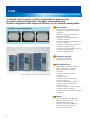
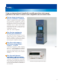
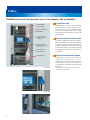
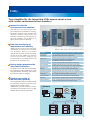
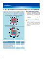
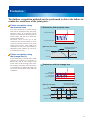
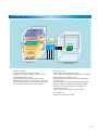
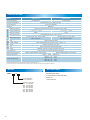
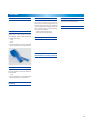
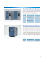
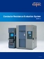
Conductor Resistance Evaluation System
AMR-U
CAT.NO.E08524
Continuous measurement of micro resistance in
solder joint and connector contact areas.
Accurate evaluation of the reliability of connections
The Conductor Resistance Evaluation System enables continuous
measurement of resistance changes under high and low temperature cycles.
Automatic measurement, data storage and processing are operated systematically with a PC.
The system realizes accurate and effective contact reliability evaluations.
1
2
AMR
CONDUCTOR RESISTANCE EVALUATION SYSTEMS
Accurately detects minute cracks in semiconductor packages and
electronic component junctions. Automatic measurement and
chamber integration allow improved efficiency in test schedule management.
Main features
● Solder crack progression
Unique multi-scan and international
Normal state
Cracking has started
Complete fracture
standards-compatible measurement
equipment.
Both direct and alternating current
application available.
Absolute value and changing rate
evaluation available.
Real time measurement enabled using
a personal computer.
Editing/ browsing of data available
during the evaluation process.
Test efficiency dramatically improved
by thermal shock chamber's
interaction with the AMR.
Evaluation targets
Printed circuit boards
Semiconductor underfill
●
Main applications
Through-hole conductor evaluation
Solder-joint contact evaluation
BGA, CSP solder joint contact
●
evaluation
Example of AMR connected with a Thermal shock chamber
Connector contact resistance
evaluation
Fpc life evaluation
Contact resistance evaluation of
switches, Relays, etc.
Lead-free solder joints evaluation
Contact resistance evaluation of
Connectors, etc.
Conductive adhesives and anisotropic
conductive films evaluation
Other interconnection material contact
evaluation
Models
With DC application (AMR-UD)
Resistance measurement range: 1103 to 1106
Minimum resolution: 100
With AC application (AMR-UA)
Resistance measurement range: 1103 to 1104
Minimum resolution: 10
●
3
Utility
Using an international standard traceable precision instrument
guarantees the most accurate and compatible measurement data.
We have always known how to
earn our customers’ confidence
AMR is equipped with highly reliable
measurement equipment and an
ammeter for micro-electric current both
desig ned to meet inter national
standards. This, to obtain most reliable
m e a s u r e m e n t d a t a . We o f f e r a
calibration ser vice to maintain the
equipment’s accuracy.
(ISO / IEC 17025 compliant)
We offer two equipments
allowing all possibillities
We offer two micro electric current
applications, the DC (AMR-UD) and
the AC (AMR-UA), which are used to
f low c u r r e n t t o s p e c i m e n s w h e n
measuring the conductor resistance.
We offer a wide range of
resistance measurement;
From 10−3 to 106Ω
Conductor resistance values ranging
from 10−3 to 106Ω(AMR-UD) and from
10 −3 t o 10 4 Ω(A M R- UA) c a n b e
precisely determined at the tip of a
measuring cable, using a four terminal
sensing.
AMR
We offer multi-channel
evaluations, thus increasing
time-saving and test accuracy
Channels can be added in 40-channel
blocks from the standard 40 channels up
to 280 channels (optional) depending on
the tests and the number of chambers to
be connected.
Measurement equipment (Agilent Technologies)
4
Utility
Multifunction rack that pursues ease of use improve the workability.
Uninterruptible
power supply
System control PC
Start button
Connection-unit
•Fixable on both right
and left sides
Installing the connection unit facilitates
the measurement cable connection. The
connection unit can be installed in front
of the rack, or either on the left or right
side of the rack according to the work
environment.
Optimum characteristics cable
Connection-unit
storage space
The cable supplied is made from Teflon,
which guarantees an excellent resistance
to noises, as well as heat. Moreover, it
enables an optimum/ accurate measurement
of micro resistances. The end of the cable
is designed to facilitate the connection to
a specimen.
Storage space
Global environmental issues
Keyboard table
•Placed inside the cabinet
when not in use
System rack
Connection unit
Measurement cable (Chamber sold separately)
5
Connection unit
Components are fixed with lead-free
solder i ng. Fu r ther more, power
consumption has been reduced by 24%
(compared to the previous model) in
consideration of global environmental
protection.
*except for purchased items such as PCs and
measuring instruments.
Utility
Tests simplified by the interaction of the measurement system
with various environmental test chambers.
Interaction with the
environmental test chamber
The AMR can be connected to three
environmental test chambers for testing.
Interaction with the environmental test
cha mber enables temper at u re a nd
humidity monitoring, management of
the time schedule, and it displays an
alarm when a failure is detected.
Real-time monitoring of
temperature and humidity
AMR monitors and records the temp.
and humid. inside the environmental
t e s t c h a m b e r. D a t a a r e r e c o r d e d
simultaneously with the measurement
carried out by the AMR. The statistics
p r o c e s si ng s of t wa r e d i s plays t he
recorded data in synchronization with
the data of the resistance tests.
Safety design guaranteed by
abnormality detection
If a failure occurs with the environmental
test equipment or the AMR, the test will
stop immediately. Resetting will resume
the test from where it stopped.
Remote processing of
the test data (optional)
LAN-compatible software enables remote
test checking and data processing, for
example from a distant office.
Additionally, we offer software licenses
according to the number of users so that
multiple PC monitoring is possible.
Example of AMR connected with a Thermal shock chamber
Function
Interaction with the thermal shock chamber (TSA Series)
Temperature
monitoring
Loads temperature data for each measurement are processed
by the AMR. Data are saved on a CSV format.
Cycle count
Analyzes the cycles performed by the chamber,
by counting and failure occurrences listing.
Start of the test
The AMR starts the test automatically,
as soon as the chamber parameters has been set.
Halt of the test
The AMR automatically stops operations of both itself
and the chamber, after being exposed to high temperature.
Resumption of
the test
Automatically resumes the halted cycle of the test as it is.
The halt history is saved in the measurement data.
Completion of the test Test automatically ends when the test is completed.
Work temperature
monitoring
The AMR take temperature measures in the chamber (randomly),
up to 16 channels. Data are saved in CSV format.
Chamber failure
detection
When a failure occurs in the chamber or the measuring
equipment fails to operate properly, the test automatically stops.
Data processing
Checks the obtained temperature data against the data of
resistance values based on the number of cycles.
Network
LAN-compatible software
(optional)
Data
LAN network
Windows®
AMR
Communication
Thermal Shock Chambers
Thermal Shock Chambers
Thermal Shock Chambers
6
Evaluation
DC or AC measurement can be selected according to your test requirements.
Example: reliability evaluation of BGA and CSP
solder ball connections (Daisy chain evaluation)
●
DC and AC application evaluation
Case in which signals between measured channels do not interfere with each
other (communication between channels is independent from each other
IC chip
Solder chip
1ch
Using DC current resistance to measure
small voltage change and detect up to
1MΩ of resistance. It is suitable for the
o b s e r v a t i o n of l a r g e c h a n g e s of
conductive resistance, such as Daisy
C h a i n of B GA i n s e m i c o n d u c t o r
applications.
AC Measurement (AMR-UA)
2ch
Using AC micro current to measure
small voltage changes without being
affected by thermal electromotive force.
It is suitable for the obser vation of
ch a nge s i n c ond uc t ive r e si st a nc e
evaluations.
4ch
3ch
●
DC Measurement (AMR-UD)
DC application only (AMR-UD only)
Case in which the measured signals interfere with each other between channels
1ch
6ch
2ch
3ch
9ch
7ch
5ch
4ch
8ch
* Compatible model differs depending on the daisy chain design for BGA and CSP
evaluations.
Evaluated item
7
DC application AC application
Evaluated item
(AMR-UD)
(AMR-UA)
Lead-free solder joints
◎
Reliability of BGA and CSP solder ball connections
◎
Contact resistance of connectors, etc.
○
Contact resistance of switches, relays, etc.
△
Conductive adhesive and anisotropic conductive films
◎
◎
Lead-free
solder joints
○
Reliability
of BGA and CSP solder ball connections
◎
Contact
resistance of connectors, etc.
◎
Contact
resistance of switches, relays, etc.
◎
Conductive
adhesive and anisotropic conductive films
DC application AC application
(AMR-UD)
(AMR-UA)
◎
◎
◎
○
○
◎
△
◎
◎
◎
Evaluation
Two failure recognition methods can be performed to detect the failure in
conductive resistance of the joint parts.
Failure recognition using
the absolute value
The date obtained at measurement
intervals are evaluated using the preset
absolute value. It will detect small
changes of conductive resistance due to
micro-cracks, and will do so until total
opening of the crack.
Ab s olu t e v a lu e c a n b e s e t i n h ot
condition and cold condition to have
separate identif ications f rom both
t empe r at u re e nd s. T he A M R w il l
terminate the test once that failure is
identified on the channel. (It can be set
to resume the test too.)
Evaluation with absolute value
Upper absolute value
Lower absolute value
• Evaluation of the measured data using the absolute value.
■
Recognizes values as the
test completion value
Upper (Ω)
Failure recognition using
the change rate (%)
This method can be used to detect small
changes of conductive resistance in
BGA and CSP. It will compare the
initial value at the starting point of the
test with the actual one, and will use the
% of difference to detect the failure. It
can be set on both ends of hot and cold
conditions.
Absolute value setting
Lower (Ω)
Evaluation with the change rate
Change rate
at high temperature
Change rate
at low temperature
• Evaluation of the measured data using the change rate.
■
Change rate setting
High
temperature side
Low
temperature side
Decision waiting period Stabilization
period
Recognizes the values as
the change rate reference values.
Upper (Ω)
Lower (Ω)
Upper (Ω)
Lower (Ω)
Stabilization Decision waiting period
period
8
SOFTWARE
●Main
window*
・Test monitoring
・Real time display of the resistance value, temperature
inside the chamber, channel on which a failure occurs
・Auto link to the data processing software
・Control commands (start, stop, pause, and restart)
* The picture shows AMR-280-UD.
●Test
condition registration
●
Test setting
Setting of:
・Duration, nb. of cycles of a test
・Duration of the measurement
・Voltage measurement
・Stress application voltage
・Limit values
These settings can be saved in a file that can
be use subsequently; numerous test conditions
can be saved for different tests and specimens.
Parameters:
・Selection of a module
・Specification of the data file name and the connected chamber
・Text documents output
・Selection /unselection of the leak-touch action mode
・Comments input
・Selection of the channel for the testing
・Test conditions' specifications
(Test conditions selected from a saved file)
●Graphic
●Cursor
display
The graph can be arranged by selecting
the channel displayed, the settings and
the cursor.
Graphs can be copied on a clipboard and
opened in another software.
(
9
The sample graph displays a resistance
value with the temperature in the thermal
shock chamber at the same time.
)
function
Quick confirmation of measurement data
and channel number is available, thanks
to the cursor function displayed on the
graphic
●Weibull
Analysis (Optional)
This data-processing software (with a
statistic processing function) enables a
Weibull analysis of test data, as well as
regular probability plotting, and
logarithmic probability trend curves.
System controller
Parallel I/O
Chamber monitor
GPIB
Uninterruptible
power supply
RS-232C
SYSTEM CONFIGURATION DIAGRAM
RS-485
Micro-current ammeter
Connection unit
Specimens
Scanner unit for
minute
resistance
measurement
System rack
●
●
System controller :
PC and LCD monitor for system control.
Measurement, data processing, chamber control.
Uninterruptible power supply :
Backup power supply for the system controller.
Automatically interrupts the test in case of power cut.
When power recovers, the test restarts from where it
was stopped. (does not resume automatically)
Environmental test chamber
(sold separately)
●
●
●
●
Chamber monitor :
Allows temperature control, monitoring,
alarm control of the chamber from the system controller.
Micro-resistance measurement unit :
Precisely measures resistance by 4-wire (resistance)
measurements.
UD type: Equipped with 34420A made by Agilent Technologies
UA type: Equipped with 4338B made by Agilent Technologies
Scanner unit for minute resistance measurement :
40 standard channels
(Optionally, up to 280 channels can be added)
Connection unit :
Relays the measurement cable.
10
SPECIFICATIONS
Model
AMR-040-UD
AMR-040-UA
Current application
DC application
AC application
Channel configuration
Standard 40ch. (max. 280ch per rack)
Control channel
A unit of 10 channels
Software
Windows 7
Connection Measurement
cable
cable
Measurement
Measuring intervals
Minimum 3 seconds (10 channels), Variable in 3-sec. steps
Resistance measurement range
1 × 10 −3 to 1 × 10⁶ Ω
1 × 10 −3 to 1 × 10⁴ Ω
Minimum resolution
100µΩ
10µΩ
10 mΩ Measured value of ±5% or less
Measurement accuracy *1
Measurement range
1Ω, 10Ω, 100Ω, 1kΩ, 10kΩ, 100kΩ,
1MΩ, and AUTO
Type
10mΩ, 100mΩ, 1Ω, 10Ω, 100Ω,
1kΩ, 10kΩ, and AUTO
Heat-resistant flat cable
Teflon (Temperature for continuous duty: +200℃ *2 )
Coated material
Length
Beyond connection unit: 1.5m
Type
Non heat-resistant measurement cable
Length
Between scanner unit and connection unit: 2.0m
Connection unit
One connection unit has 40-channel connection.
Measurement equipment
Model: 34420A (Agilent Technologies)
Model: 4338B (Agilent Technologies)
530W × 1750H × D940D mm
External dimension
100V AC,
120V AC,
220V AC,
240V AC,
Power supply facility
1φ,10.0A
1φ,8.3A
1φ,4.5A
1φ,4.2A
*1Value guaranteed at end of measurement cable of a standard system.
*2The solder used for connections has to be chosen by the customer, regarding its temperature resistance.
MODEL
ACCESSORIES
AMR - - U
Measurement cable
Communication cable (RS-485)
Setup CD
User’s manual
●
●
D: DC application
A: AC application
Number of channels
040 : 40 channels
080 : 80 channels
120 : 120 channels
160 : 160 channels
200 : 200 channels
240 : 240 channels
280 : 280 channels
11
●
●
OPTIONS
Additional channel (40 channel basis)
Heat-resistant measurement cable
Identical to the heat-resist ant
measurement Teflon cable included as
a standard accessory.
・1.5 m
・2.5 m
・3.5 m
* Can be extended in 1 meter increments
upon request at the time of purchase.
Specimen temperature monitor
Emergency stop switch
Specimen temperat u re monitor
measures the surface temperature of
the specimen and saves the specimen
surface temperature and the measured
data simultaneously. The following
two types are available.
・8 points measurement type
・16 points measurement type
Stops the system immediately.
Communication cable
LAN-compatible software
Data processing software
(with statistic processing software)
Colored heat-resistant cable
Provides different colored cables for
each channel.
・1.5 m
* Can be extended in 1 meter increments
upon request at time of purchase.
Non heat-resistant measurement cable
(extension)
12
MEASUREMENT SYSTEMS
Ion Migration Evaluation System
AMI
Makes stress evaluations and insulation resistance evaluations by
electrochemical migration efficient and easy, and covers a broad
spectrum, from low-voltage to high-voltage tests.
■
●
●
●
Evaluation Targets
Printed circuit boards
Insulation materials
Semiconductor materials
Semiconductor Parametric Test System
AMM
Supports cutting-edge device evaluation and offers
highly-reliable data acquisition, collection, and analysis over
a wide range of evaluation conditions from reliability evaluations
to test/characteristic evaluations.
■
Evaluation Targets
●
●
●
Semiconductor transistors
Low-k materials
High-k materials
Electromigration Evaluation System
AEM
Space-saving all-in-one system, the AEM is the only product of
its kind in the industry to offer electromigration evaluation of
1μA at 400℃.
■
Evaluation Targets
●
●
Semiconductor wiring patterns
Solder bumps
Flash Memory Endurance Cycling System
RBM-LCT
A Monitored Burn-in System for evaluation testing of
non-volatile memory, such as Flash memory or FeRAM.
This testing/evaluation equipment is suited to a variety of
uses from R&D to mass production.
■
Evaluation Targets
●
13
Flash memory (FeRAM and MRAM)
VARIOUS ENVIRONMENTAL TEST CHAMBERS〈SOLD SEPARATELY〉
Thermal Shock Chamber TSA Series
TSA series is the series that reduces the temperature
recovery time, temperature heat-up time, and temperature
pull-down time. TSA series has HFC refrigerant and a touchpanel that facilitates operation setting changes.
TSA Series is presented as environment-friendly series.
Model
Temperature range
Inside dimensions (mm)
TSA—71S
W410×H460×D370
High temp. chamber:+60 to +200℃
W650×H460×D370
TSA—101S
Low temp. chamber:−70 to 0℃
W650×H460×D670
TSA—201S
TSA—41L
W240×H460×D370
TSA—71L
TSA—101L
High temp. chamber:+60 to +200℃ W410×H460×D370
Low temp. chamber:−65 to 0℃
W650×H460×D370
TSA—301L
W970×H460×D670
Thermal Shock Chamber TSD-100
TSD-100 is a thermal shock chamber with two zones that
conforms to Japanese and international test standards such as
MIL-STD-883, JIS C 0025 and JASO-D001. With excellent
temperature distribution performance, this chamber applies
uniform temperature stress to specimens. Furthermore, by
monitoring specimen temperature with the STT function,
this chamber starts counting exposure time and switches to
the next step immediately after the specimen temperature
reaches a preset value, thus enabling highly accurate tests. In
the temperature range between 60 and 150, this chamber has
a short return time of 15 minutes, allowing a reduction of the
total test time. This chamber can be used in a variety of
purposes, from research and development to inspection and
production.
Model
TSD—100
Temperature range
Inside dimensions (mm)
High temp. chamber:+60 to +200℃
W710×H345×D410
Low temp. chamber:−65 to 0℃
14
http://www.espec.co.jp/english
Head Office
3-5-6, Tenjinbashi, Kita-ku, Osaka 530-8550, Japan
Tel : 81-6-6358-4741
Fax : 81-6-6358-5500
ESPEC NORTH AMERICA, INC.
Tel : 1-616-896-6100 Fax : 1-616-896-6150
ESPEC EUROPE GmbH
Tel : 49-89-1893-9630 Fax : 49-89-1893-96379
ESPEC ENVIRONMENTAL EQUIPMENT (SHANGHAI) CO., LTD.
Head Office
Tel : 86-21-51036677 Fax : 86-21-63372237
BEIJING Branch
Tel : 86-10-64627025 Fax : 86-10-64627036
TIANJIN Branch
Tel : 86-22-26210366 Fax : 86-22-26282186
GUANGZHOU Branch
Tel : 86-20-83317826 Fax : 86-20-83317825
SHENZHEN Branch
Tel : 86-755-83674422 Fax : 86-755-83674228
SUZHOU Branch
Tel : 86-512-68028890 Fax : 86-512-68028860
ESPEC TEST TECHNOLOGY (SHANGHAI) CO., LTD.
Tel : 86-21-68798008 Fax : 86-21-68798088
ESPEC (MALAYSIA) SDN. BHD.
Tel : 60-3-8945-1377 Fax : 60-3-8945-1287
ESPEC CORP. has been assessed by and
registered in the Quality Management System
based on the International Standard ISO
9001:2008 (JIS Q 9001:2008) through the
Japanese Standards Association (JSA).
●
W6E20C03 (The contents of this catalog is as of June, 2008.)
●
ESPEC CORP.
Specifications are subject to change without notice due to design improvements.
Corporate names and trade names mentioned in this catalog are trademarks or registered trademarks.