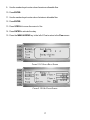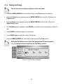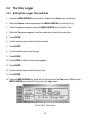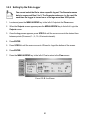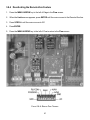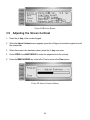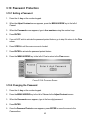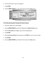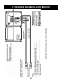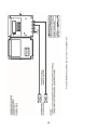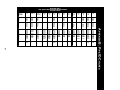
1
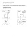
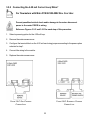
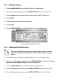
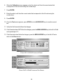
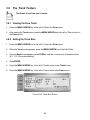
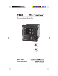
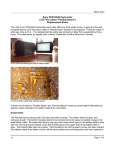
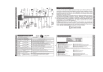
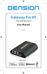
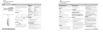
Dedicated Dual Frequency
Doppler Ultrasonic Flowmeter
USER MANUAL
Rev. E (06/02)
HYDRA SX40
USER MANUAL
JUNE 2002
REV. E
NOTICE
Read this manual before working with the product. For personal and system safety and
for optimum performance, make sure you thoroughly understand the contents before
installing, using, or maintaining this instrument.
For equipment service needs outside the United States contact your nearest Flow Systems representative.
Within the United States, the Thermo Electron–Flow Systems Service Department is your
single-point contact for all Thermo Polysonics equipment service needs. If at any time
you are not sure what to do, you have a question about using the product, or you have a
service or support request, call the service department at (713) 272-0404. This contact is
your fastest link to quick and complete answers about any Thermo Electron–Flow Systems product or service.
Thermo Electron Corporation
Flow Systems
9303 W. Sam Houston Pkwy S.
Houston, TX 77099
Phone: (713) 272-0404
Fax: (713) 272-5388
Web: www.thermoflowsystems.com
TABLE OF CONTENTS
1. General ............................................................................................................ 1
1.1 Flowmeter Specifications .............................................................................. 1
1.1.1 Performance Specifications ..................................................................... 1
1.1.2 Physical Specifications ............................................................................ 1
1.1.3 Functional Specifications ......................................................................... 2
1.2 Industry Approvals ........................................................................................ 2
2. Meter Installation .............................................................................................. 3
2.1 Wiring the Meter ............................................................................................ 3
2.1.1 Connecting the AC Power ........................................................................ 3
2.1.2 Connecting the DC Power........................................................................ 4
2.1.3 Connecting the Transducers .................................................................... 5
2.2 Installing the Meter ........................................................................................ 8
2.2.1 Selecting a Transducer Site ..................................................................... 8
2.2.2 Choosing a Transducer Orientation ......................................................... 8
2.2.3 Attaching Transducers to the Pipe Strap ................................................. 9
2.2.4 Mounting the Transducers ..................................................................... 10
2.2.5 Mounting the Meter Enclosure ............................................................... 11
2.3 Measuring Flow ........................................................................................... 11
3. Meter Operation ............................................................................................. 14
3.1 Relays ......................................................................................................... 14
3.1.1 Connecting the Relays ........................................................................... 14
3.1.2 Configuring the Relays ........................................................................... 16
3.1.3 Testing the Relays .................................................................................. 18
3.2 The Data Logger ......................................................................................... 19
3.2.1 Setting Data Logger Time and Date ....................................................... 19
3.2.2 Setting Up the Data Logger.................................................................... 20
3.2.3 Downloading Data from the Data Logger ............................................... 21
3.2.4 Saving Data Log Files ............................................................................ 23
3.2.5 Loading Data Log Files .......................................................................... 24
3.2.6 Erasing Data Log Files ........................................................................... 25
3.2.7 Zooming in on Data ................................................................................ 26
3.2.8 Zooming in on a Selection of Data ......................................................... 27
3.3 The Totalizer................................................................................................ 28
3.3.1 Setting Totalizer Units ............................................................................ 28
3.3.2 Changing the Totalizer Multiplier ............................................................ 29
3.3.3 Resetting the Totalizer ........................................................................... 29
3.4 The Pulse Totalizer Feature ........................................................................ 29
3.4.1 General .................................................................................................. 29
3.4.2 Activating the Pulse Totalizer ................................................................. 30
3.4.3 Reconfiguring the Pulse Totalizer Multiplier ........................................... 30
3.4.4 Deactivating the Pulse Totalizer ............................................................. 31
3.5 The 4-20 mA Loop ...................................................................................... 31
3.5.1 Connecting the 4-20 mA Current Loop Wires* ....................................... 31
3.5.2 Connecting the 4-20 mA Current Loop Wires* ....................................... 33
3.5.3 Setting the Range .................................................................................. 34
3.5.4 Calibrating the 4-20 mA Loop ................................................................ 34
3.6 The Trend Feature ...................................................................................... 36
3.6.1 Viewing the Flow Trend .......................................................................... 36
3.6.2 Setting the Trend Rate ........................................................................... 36
3.6.3 Viewing the Maximum Flow ................................................................... 37
3.6.4 Resetting the Maximum Rate ................................................................. 37
3.7 The Lost Power Feature .............................................................................. 38
3.7.1 General .................................................................................................. 38
3.7.2 Activating the Lost Power Feature ......................................................... 38
3.7.3 Resetting the Lost Power Feature .......................................................... 38
3.7.4 Deactivating the Lost Power Feature ..................................................... 39
3.8 The Remote Zero Feature ........................................................................... 39
3.8.1 General .................................................................................................. 39
3.8.2 Connecting a Switch to Remote Zero Feature ....................................... 40
3.8.3 Activating the Remote Zero Feature ...................................................... 40
3.8.4 Deactivating the Remote Zero Feature .................................................. 41
3.9 Adjusting the Screen Contrast .................................................................... 42
3.10 Password Protection ................................................................................. 43
3.10.1 Setting a Password .............................................................................. 43
3.10.2 Changing the Password ....................................................................... 43
3.10.3 Deactivating the Password Protect Feature ......................................... 44
4. Troubleshooting .............................................................................................. 45
4.1 Modes of Operation..................................................................................... 45
4.2 Learn Mode Warnings ................................................................................. 45
4.3 Operating Mode Warnings & Faults ............................................................ 46
4.4 Variable Frequency Drives (VFD’s) ............................................................. 47
4.5 Checking the FFT ........................................................................................ 48
4.6 Setting a Low Flow Cutoff ........................................................................... 49
4.7 Performing On-Site Calibrations ................................................................. 50
4.8 Resetting to Factory Defaults ...................................................................... 50
4.9 Setting a Damping Parameter ..................................................................... 50
4.10 Signal Quality & Signal Strength ............................................................... 51
5. Maintenance & Upgrades ............................................................................... 52
5.1 General ....................................................................................................... 52
5.2 Local Representative Support ..................................................................... 52
5.3 Flowmeter Maintenance .............................................................................. 52
5.4 Maintenance Procedures ............................................................................ 53
5.4.1 Replacing the 4-20 mA Module .............................................................. 53
5.4.2 Replacing the Relays ............................................................................. 54
5.4.3 Replacing the Fuse ................................................................................ 54
5.5 Upgrading the Flowmeter ............................................................................ 55
5.6 Contacting the Service Department ............................................................ 56
5.7 Returning Flowmeters ................................................................................. 56
6. Hazardous Area Installation Methods ............................................................ 58
Appendix A: Obtaining Pipe ID ........................................................................... 60
Appendix B: Pipe ID Charts................................................................................ 61
Appendix C: Hydra SX40 Menu Tree ................................................................. 64
1. GENERAL
The Hydra SX40 Dual Frequency Doppler (DFD) Dedicated Flowmeter is suited for measuring the
flow of fluids with undissolved, entrained solids or dispersed gases such as:
•
•
•
wastewater–primary sludge and activated sludge,
food–dairy and fluidized foods,
industrial–crude oil and dredging.
1.1
Flowmeter Specifications
1.1.1 Performance Specifications
Velocity Range: 0.2 ft/sec to 32 ft/sec (0.06 m/sec to 10 m/sec)
Accuracy: ±1% of velocity full scale
Fluids: liquids containing particulate or entrained gas bubbles
Pipe Size: 0.5 in to 200 in (12 mm to 5000 mm)
1.1.2 Physical Specifications
Transmitter: NEMA 4X (IP 65), flame retardant, fiberglass-reinforced polyester
Transducers: two encapsulated DFD sensor heads suitable for submersible/underground service;
enclosed in stainless steel shrouds with integral transducer clamps
30 ft (9 m) standard cable length
Weight: approximately 12 lbs (5.4 kg)
1
1.1.3 Functional Specifications
Outputs:
4-20 mA (into 750 Ohms), 12-bit, 5 kV, optically isolated; loop- or self-powered;
RS232 interface
Power Supply: 90 to 132 VAC and 190 to 250 VAC, 50/60 Hz (switch selectable); 11 to 28 VDC
Temperature
Transducers:
-40ºF to +250ºF (-40ºC to +121ºC)
Transmitters:
-20ºF to +140ºF (-29ºC to +140ºC)
(with integral heater) -40ºF to +140ºF (-40ºC to +60ºC)
Keypad: 19-key with tactile action
Display: high resolution, 240 x 60 dot, backlit graphics display
Data Logger: 90,000-point data logger; programmable in log intervals of 30 sec, 1, 5, 15, 30, and
60 mins
1.2
Industry Approvals
The Hydra SX40 is approved for installation in the following Hazardous Areas classifications:
•
Flowmeter: Nonincendive (Class I, Div 2 and Class II, Div 2)
•
Transducers:
Intrinsically Safe (Class I, Div 1 and Class II, Div 1)
Nonincendive (Class I, Div 2 and Class II, Div 2)
The Hydra SX40 also meets European CE requirements.
2
2. METER INSTALLATION
2.1
Wiring the Meter
2.1.1 Connecting the AC Power
Connecting AC power to a DC-powered meter may damage the meter.
Prevent possible electrical shock and/or damage to the meter–disconnect
power to the meter PRIOR to wiring.
If the meter is located close to a variable frequency drive, install the
power lines in a grounded metal conduit.
CE certifications requires that a switch or circuit breaker be installed in
close proximity to the SX40 and be labeled as the SX40 disconnect.
Reference Figure 2.1-A (page 4).
1. Remove the meter access cover.
2. Determine the voltage of the power line you are connecting to the meter–110 or 220 volts.
3. Locate the AC input voltage selector.
4. Turn the voltage selection switch to 110 or 220 to match the power line voltage.
5. Locate the power input block, and locate the L1, L2/N, and GND connections within the block.
6. Turn the terminal screws on top of the power input block COUNTERCLOCKWISE to fully open
the wire connections.
7. Insert the ground wire into the GND connection.
8. Insert the hot wire into the L1 connection.
9. If you selected 110 volts, insert the neutral wire into L2/N connection; if you selected 220 volts,
insert the other hot wire into L2/N connection.
10. Turn each screw on top of the wire connections CLOCKWISE to close the connections.
11. Ensure the wires are securely connected to the input block, and replace the meter access
cover.
3
•
•
•
L1–hot wire
L2/N–neutral wire (110 volts) OR second hot wire (220
volts)
GND*–ground wire
*CE certification requires less than 1 Ohm between
terminal and ground.
FIGURE 2.1-A: AC POWER SETUP
2.1.2 Connecting the DC Power
Later versions of the SX40 (with P/N 22686-0002, Rev. G) have DC operation built into the
flowmeter. Refer to Figure 2.1-B (page 5), and connect +24 VDC to P2 +24V and 24 VDC return to
either of the P2 GND.
4
FIGURE 2.1-B: DC POWER SETUP
2.1.3 Connecting the Transducers
Prevent possible electrical shock and/or damage to the meter–disconnect
power to the meter PRIOR to wiring.
Reference Figures 2.1-C and 2.1-D (pages 6-7).
1. Remove the meter access cover.
2. Remove the nut from the transducer cable connector.
5
3. Draw the transducer cable through the opening in the meter enclosure.
4. Thread the nut onto the cable connector to inside of meter enclosure.
5. Tighten the nut to 15 ft-lbs of torque using a torque wrench.
6. Locate the transducer I/F block.
7. Locate the XMT(DN), XMTGND, RCV (UP), and RCVGND wire connections.
8. Turn the screws on top of transducer block COUNTERCLOCKWISE to fully open the wire
connections.
9. Identify the following transducer wires:
•
(2) signal wires,
•
(2) braided ground wires.
10. Insert the first signal wire into the XMT (DN) connection.
11. Insert the first braided ground wire into the XMT GND connection.
12. Insert the second signal wire into the RCV (UP) connection.
13. Insert the second braided ground wire into the RCV GND connection.
14. Turn each of screw on top of connections CLOCKWISE to close the connections.
15. Ensure wire connections are secure, and replace the meter access cover.
FIGURE 2.1-C: TRANSDUCER CABLE SEAL ASSEMBLY
6
•
•
•
•
XMT (DN)–first signal wire
XMT GND–first braided ground wire
RCV (UP)–second signal wire
RCV GND–second braided ground
wire
FIGURE 2.1-D: TRANSDUCER BLOCK
7
2.2
Installing the Meter
2.2.1 Selecting a Transducer Site
Figure 2.2-A and the following questions will assist you when choosing a proper installation
location:
•
•
Is the chosen section of pipe always full of liquid?
Are there at least five pipe diameters upstream and three pipe diameters downstream from any
directional changes, pipe joints, or narrowing/widening of the pipe?
Conditions at locations A, B, C, D, and E can
interfere with the transmission of the
ultrasonic wave and yield inaccurate or
unreliable flow readings.
•
•
•
•
•
A–pipe may not be full
B–down flow
C–too close to elbow
D–air collects at top of horizontal pipe
E–sediment collects at bottom of
horizontal pipe
FIGURE 2.2-A
2.2.2 Choosing a Transducer Orientation
Selecting the proper installation location is essential to flow measurement
reliability. Each application is unique and may require a variation of
installation locations.
Reference Figure 2.2-B (page 9) and the following guidelines to ensure optimum meter performance:
•
•
•
•
If your application allows, install the transducers at the 3 and 9 o’clock locations.
Ensure the transducers are parallel to one another along the pipe circumference.
Ensure the cable connections are secure.
Tighten the pipe strap.
8
FIGURE 2.2-B
2.2.3 Attaching Transducers to the Pipe Strap
1. Use a screwdriver to
loosen the mounting
screw on each
transducer.
3. Place pipe strap
across the mounting.
2. Slide the lock back on
each transducer.
4. Slide lock back into
place.
9
5. Tighten the screws.
Increasing the pipe strap tension improves
signal transmission.
2.2.4 Mounting the Transducers
1. Wrap the pipe strap around pipe.
2. Slide end of pipe strap through the tension nut assembly.
3. Pull strap tightly, AND clamp tension nut down to secure pipe strap to pipe.
4. Loosen the mounting screw of one transducer.
5. Move transducer to the 3 o’clock position on pipe, and tighten mounting screw to secure
transducer.
6. Repeat step 4 with remaining transducer.
7. Move transducer to 9 o’clock position on pipe, and tighten mounting screw to secure
transducer.
8. Remove pipe strap from pipe, and apply sonic coupling compound to each transducer surface.
9. Reposition pipe strap on pipe, placing the transducers in the proper positions.
10. Tighten tension nut assembly with a 3/8-inch hex nut driver to secure pipe strap.
10
2.2.5 Mounting the Meter Enclosure
To prevent the possibility of electrical shock and/or damage to the meter,
DO NOT mount the enclosure where it can be submerged or partially
submerged.
1. Locate a sturdy, vertical mounting surface.
2. Remove the meter access cover.
3. Locate the 4 mounting holes (1 in each corner of meter cover).
4. Attach the enclosure to the wall using mounting screws.
5. Replace the meter access cover.
An optional mounting ear package is also available.
2.3
Measuring Flow
You must know the pipe internal diameter (ID) to ensure reliable flow
measurements, AND there must be flow in the pipe when you start the
meter.
1. If you do not know the pipe ID, go to Appendix A (page 60).
2. Apply power to the meter. You are now in Start-up Mode.
3. After the Pipe ID screen appears, press SCROLL to select the correct unit for the pipe ID
(inches, mm).
4. Press ENTER.
5. Use the number keys to enter pipe ID.
If you make an error when entering a number, press the BACKSPACE key
to move the cursor to the incorrect number, and enter the correct number.
6. Press Enter.
7. Press Scroll to select the correct pipe material.
11
8. Press Enter.
9. Locate the MENU ARROW key to the left of Next, and press it.
10. After the Flow Units screen appears, press SCROLL to move the cursor to the required
volume units.
11. Press ENTER.
12. Press SCROLL until the cursor moves to the correct time base units.
13. Press ENTER.
14. Press the MENU ARROW key again to enter Learn Mode.
MENU ARROW KEY
ð
FIGURE 2.3-A: PIPE ID SCREEN
MENU ARROW KEY
ð
FIGURE 2.3-B: FLOW UNITS SCREEN
15. Wait for the Learn Mode screen to appear.
If you operate the meter without installing it, press the ENTER key 4 times
to bring up the flow screen.
12
16. The Learn Mode screen displays diagnostic information for 60 seconds. Review this
information, and reference Sections 4.1, 4.2, and 4.3 (pages 45-46) if any of the following
warnings appear:
•
•
•
•
Invalid Signal, Can’t Learn,
No Flow, Can’t Learn,
Warning Low S Strength,
Warning Poor S Strength.
17. When the meter goes into Operating Mode, wait for the Flow screen to appear.
18. Read the flow.
a. If the flow reading is not accurate and you can verify the flow from a calibrated flowmeter or
other certified source, reference Section 4.7 (page 50).
b. Reference Section 4.3 (page 46) if any of the following warnings appear:
•
•
•
Warning,
Alarm,
Failed/No Flow.
FIGURE 2.3-C: LEARN MODE SCREEN
FIGURE 2.3-D: FLOW SCREEN
13
3. METER OPERATION
3.1
Relays
3.1.1 Connecting the Relays
Prevent possible electrical shock and/or damage to the meter–disconnect
power to the meter PRIOR to wiring.
1. Remove meter access cover.
2. Locate the 4 relay terminal blocks (reference Figure 3.1-A, page 15).
3. Select one of the installed relays to wire.
4. Locate the following relay contacts on the relay terminal block:
•
•
•
Normally Closed (NC),
Common (C),
Normally Open (NO).
When the relay is at rest the circuit is closed between the NC and C
terminals and open between the NO and C terminals. When the relay is
energized the circuit is open between the NC and C terminals and closed
between the NO and C terminals.
5. Turn the terminal screw on top of each wire connection COUNTERCLOCKWISE to fully open
the connections.
6. Insert the wires for your control system into the corresponding wire connections.
7. Turn the terminal screw on top of each wire connection CLOCKWISE to close the connections.
8. Ensure wire connections are secure.
9. Go to Section 3.1.3 (page 18) to test the relay.
10. Replace the meter access cover.
14
FIGURE 3.1-A: RELAYS & RELAY TERMINAL BLOCKS
15
FIGURE 3.1-B: RELAY SCHEMATIC
3.1.2 Configuring the Relays
Relay 1 is dedicated as the pulse totalizer; relay 4 is dedicated as the lost
power monitor. Therefore, if the pulse totalizer and lost power features
are active, relays 1 and 4 CANNOT be configured using this procedure.
Reference Sections 3.4 and 3.7 (pages 29, 38) for information on these
features.
1. Locate the MENU ARROW key to the left of Output in the Flow screen, and press it.
2. When the Output screen appears, press the MENU ARROW key to the left of Relays.
3. Once the Select Relay screen appears, press SCROLL to move the cursor to the relay you
want to configure.
4. Press ENTER.
5. Press the MENU ARROW key to the left of Set Pts, and the Set Points screen appears.
6. Determine the following:
•
•
maximum allowable flow,
if relay is to turn on (energize) or off (rest) when flow is greater than maximum acceptable
flow.
7. If you want the relay to energize when flow is greater than maximum acceptable flow, press
SCROLL to move the cursor to On, OR if you want the relay to rest when flow is greater than
maximum acceptable flow, press SCROLL to move the cursor to Off.
8. Press ENTER.
16
9. Use the number keys to enter value of maximum allowable flow.
10. Press ENTER.
11. Use the number keys to enter value of minimum allowable flow.
12. Press ENTER.
13. Press SCROLL to move the cursor to Yes.
14. Press ENTER to activate the relay.
15. Press the MENU ARROW key to the left of Flow to return to the Flow screen.
FIGURE 3.1-C: SELECT RELAY SCREEN
FIGURE 3.1-D: SET POINTS SCREEN
17
3.1.3 Testing the Relays
You do not have to configure relays in order to test them.
1. Locate the MENU ARROW key to the left of Output in the Flow screen, and press it.
2. When the Output screen appears press the MENU ARROW key to the left of Relays in the
Output screen.
3. Once the Select screen appears, press the MENU ARROW key to the left of Test in the
Select Relay screen.
4. The Test Relays screen appears; press SCROLL to move the cursor to the relay you want to
test.
5. Press ENTER to switch the relay to On (energize).
6. Press ENTER again to switch the relay to Off (at rest).
7. Press the MENU ARROW key to the left of Flow to return to the Flow screen.
Exiting the Test Relays screen sets all the relays to the Off (at rest) position,
i.e., you cannot activate relays from the Test Relays screen.
FIGURE 3.1-E: TEST RELAYS SCREEN
18
3.2
The Data Logger
3.2.1 Setting Data Logger Time and Date
1. Locate the MENU ARROW key to the left of Outputs in the Flow screen, and press it.
2. When the Outputs screen appears press the MENU ARROW key to the left of Log.
3. Once the Log screen appears, press the MENU ARROW key to the left of Time.
4. When the Time screen appears, use the number keys to enter the correct hour.
5. Press ENTER.
6. Use the number keys to enter the correct minutes.
7. Press ENTER.
8. Use the number keys to enter the day.
9. Press ENTER.
10. Press SCROLL until the correct month appears.
11. Press ENTER.
12. Use the number keys to enter the correct year.
13. Press ENTER.
14. Press the MENU ARROW key to the left of Flow to return to the Flow screen, OR press the
MENU ARROW key to the left of Log to go to the Log screen.
FIGURE 3.2-A: TIME SCREEN
19
3.2.2 Setting Up the Data Logger
You cannot select the file to store a specific log set. The flowmeter saves
data in sequenced files 0 to 9. The flowmeter advances to the next file
each time the logger is turned on or a file logs more than 9000 points.
1. Locate and press the MENU ARROW key to the left of Outputs in the Flow screen.
2. When the Outputs screen appears press the MENU ARROW key to the left of Log in the
Outputs screen.
3. Once the Log screen appears, press SCROLL until the cursor moves to the desired time
between points (30-second, 1-, 5-, 15-, 60-minute intervals).
4. Press ENTER.
5. Press SCROLL until the cursor moves to ON next to Log at the bottom of the screen.
6. Press ENTER.
7. Press the MENU ARROW key to the left of Flow to return to the Flow screen.
FIGURE 3.2-B: LOG SCREEN
20
3.2.3 Downloading Data from the Data Logger
HydraLink software must be installed on your computer in order to perform
this function.
1. Connect the communication cable from the flowmeter to the RS232 port on the computer.
2. Open HydraLink.
3. If the Communications Established window appears, click OK and proceed to step 4.
However, if the Communications Failed window appears, check the security of the cable,
ensure the flowmeter is on, and complete the following steps:
a. Click OK.
b. When the CommPort Properties window appears, make sure the correct comm port
number is selected, and enter the correct CommPort properties.
c. The Communication Established window should appear. If it does not, contact your
Flow Systems representative.
FIGURE 3.2-C: COMMPORT PROPERTIES
21
4. When the HydraLink window opens, click on the drop-down arrow next to Log File 0.
5. Select the log file you want to download.
6. Click the Get Log button in the upper right corner of the HydraLink window.
7. Wait for HydraLink to complete downloading.
FIGURE 3.2-D
The logger saves data in sequenced files 0 through 9. Once all files are
full, the logger restarts the sequence and overwrites the files beginning
with log file 0. Refer to Section 3.2.4 (page 23) to save log files.
22
3.2.4 Saving Data Log Files
Saved data log files are delimited by commas, as it applies to opening
the files in spreadsheet programs.
1. Click on File in the HydraLink window.
2. Select Save Log.
3. Use standard Windows procedures to save the log file on your computer or floppy disk.
FIGURE 3.2-E
23
3.2.5 Loading Data Log Files
The flowmeter MUST be connected to your PC for this procedure.
1. Click on File in the HydraLink window.
2. Select Load Log.
3. Use standard Windows procedures to retrieve the log file from your computer or floppy disk.
FIGURE 3.2-F
24
3.2.6 Erasing Data Log Files
Performing the following procedure will erase ALL the log information
stored in the flowmeter. You CANNOT erase a specific log file.
1. Click on Log in the HydraLink window.
2. Select Erase All.
3. If you are sure you want to erase all 10 log files, click Yes in the Erase All window, and wait
while the logger erases all the files.
4. If you do not want to erase all 10 log files, click No in the Erase All window. Click OK in the
Erase Aborted window.
FIGURE 3.2-G
25
3.2.7 Zooming in on Data
1. Click in the check box to the left of Zoom.
2. Press the arrow buttons at the bottom of the data graph to view data.
3. Return to the original view by clicking in the Zoom check box again.
FIGURE 3.2-H
26
3.2.8 Zooming in on a Selection of Data
1. Move your mouse to a point on the screen.
2. Depress the mouse button, and drag the mouse to enclose the range of data you want to zoom
in on.
3. Release the mouse button.
4. Repeat steps 1-3 until you achieve your desired view.
5. Return to the original view by clicking in the Zoom check box.
FIGURE 3.2-I
27
FIGURE 3.2-J
3.3
The Totalizer
3.3.1 Setting Totalizer Units
1. Press the MENU ARROW key to the left of Diags in the Flow screen.
2. When the Limits screen appears, press the MENU ARROW key to the left of Total.
3. Once the Total screen appears, press SCROLL to move the cursor to the correct volume units.
4. Press ENTER.
5. Press the MENU ARROW key to the left of Flow to return to the Flow screen.
28
3.3.2 Changing the Totalizer Multiplier
1. Press the MENU ARROW key to the left of Diags in the Flow screen.
2. When the Limits screen appears, press the MENU ARROW key to the left of Total.
3. Once the Total screen appears, press ENTER to move the cursor to the multiplier box.
4. Press SCROLL until the desired multiplier appears in the box.
5. Press ENTER to set the multiplier.
6. Press the MENU ARROW key to the left of Flow to return to the Flow screen.
3.3.3 Resetting the Totalizer
1. Press the MENU ARROW key to the left of Diags in the Flow screen.
2. When the Limits screen appears, press the MENU ARROW key to the left of Total.
3. Once the Total screen appears, press ENTER twice to move the cursor to Reset?.
4. Press SCROLL until Reset? reads Yes.
5. Press ENTER.
6. After the totalizer resets, press the MENU ARROW key to the left of Flow to return to the
Flow screen.
3.4
The Pulse Totalizer Feature
3.4.1 General
The pulse totalizer is designed to send a pulse whenever a preset rate of total flow occurs. The
pulse is received by some external device set up in the relay loop. Relay 1 is the dedicated pulse
totalizer relay. This feature is ideal for applications requiring a total flow reading from an external
device such as an electromechanical counter. For example, setting up the pulse totalizer to send a
pulse every thousand gallons of flow causes the pulse totalizer to send a pulse to the
electromechanical counter for every thousand gallons of flow; the counter then records 1 unit. Refer
to Section 3.1 (page 14) to connect the pulse totalizer.
29
3.4.2 Activating the Pulse Totalizer
1. Press the MENU ARROW key to the left of Diags in the Flow screen.
2. When the Limits screen appears, press the MENU ARROW key to the left of Total.
3. Once the Totalizer screen appears, press ENTER 3 times to move the cursor to No in the last
line of the screen (reads Tot RLY 1).
4. Press SCROLL until the desired multiplier (x1, x2, x5, x10) appears in the box.
5. Press ENTER to activate the pulse totalizer feature.
6. Press the MENU ARROW key to the left of Flow to return to the Flow screen.
The pulse totalizer multiplier is NOT independent of the totalizer multiplier.
For example, if the totalizer multiplier is set to x10 gallons and the pulse
totalizer multiplier is set to x2 gallons, then the pulse totalizer will send a
pulse every 20 gallons.
3.4.3 Reconfiguring the Pulse Totalizer Multiplier
1. Press the MENU ARROW key to the left of Diags in the Flow screen.
2. When the Limits screen appears, press the MENU ARROW key to the left of Total.
3. Once the Totalizer screen appears, press ENTER 3 times to move the cursor to multiplier in
the last line of the totalizer screen (reads Tot RLY 1).
4. Press SCROLL until the desired multiplier for the pulse totalizer appears in the box.
5. Press ENTER to activate the new multiplier.
6. Press the MENU ARROW key to the left of Flow to return to the Flow screen.
30
3.4.4 Deactivating the Pulse Totalizer
1. Press the MENU ARROW key to the left of Diags in the Flow screen.
2. When the Limits screen appears, press the MENU ARROW key to the left of Total.
3. Once the Totalizer screen appears, press ENTER 3 times to move the cursor to the multiplier
in the last line of the totalizer screen (reads Tot RLY 1).
4. Press SCROLL until No appears in the box.
5. Press ENTER to deactivate the pulse totalizer feature.
6. Press the MENU ARROW key to the left of Flow to return to the Flow screen.
FIGURE 3.4: TOTALIZER/PULSE TOTALIZER SCREEN
3.5
The 4-20 mA Loop
3.5.1 Connecting the 4-20 mA Current Loop Wires*
* For flowmeters with Main PCB 22302-0002 Rev. F or earlier.
Prevent possible electrical shock and/or damage to the meter–disconnect
power to the meter PRIOR to wiring.
Use shielded twisted pair wires for this connection. If the meter is installed
near VFD’s, install wiring in grounded metal conduit.
Reference Figures 3.5-A and 3.5-B (page 32) for each step of this procedure.
31
1. Select a powering option for the 4-20 mA loop.
2. Remove the meter access cover.
3. Configure the pins on the 4-20 mA card using jumpers according to the power option selected
in step 1.
4. Connect the wiring to the module.
5. Replace the meter access cover.
FIGURE 3.5-A: SELF-POWERED
CURRENT LOOP AND PIN CONFIGURATION
FIGURE 3.5-B: EXTERNALLY POWERED
CURRENT LOOP AND PIN CONFIGURATION
32
3.5.2 Connecting the 4-20 mA Current Loop Wires*
For flowmeters with Main PCB 22302-0002 Rev. G or later.
Prevent possible electrical shock and/or damage to the meter–disconnect
power to the meter PRIOR to wiring.
Reference Figures 3.5-C and 3.5-D for each step of this procedure.
1. Select a powering option for the 4-20 mA loop.
2. Remove the meter access cover.
3. Configure the terminal block on the 4-20 mA card using jumpers according to the power option
selected in step 1.
4. Connect the wiring to the module.
5. Replace the meter access cover.
FIGURE 3.5-C: SELF-POWERED
CURRENT LOOP
FIGURE 3.5-D: EXTERNALLY POWERED
CURRENT LOOP
33
3.5.3 Setting the Range
1. Press the MENU ARROW key to the left of Output in the Flow screen.
2. When the Log screen appears, press the MENU ARROW key to the left of 4-20 mA.
3. Once the Range screen appears, enter the minimum flow using the number keys.
4. Press ENTER.
5. Enter the maximum flow using the number keys.
6. Press ENTER.
7. Press the MENU ARROW key to the left of Flow to return to the Flow screen.
FIGURE 3.5-E: 4-20 MA RANGE SCREEN
3.5.4 Calibrating the 4-20 mA Loop
You need a calibrated current meter to perform this procedure. If you are
using the loop-powered configuration, you will also need a DC power
source.
1. Set up a calibration current loop according to Section 3.5.1 or 3.5.2 (pages 31-33).
2. If the meter is NOT on a pipe with flow, press the MENU ARROW key to the left of Next two
times, and press ENTER four times to access the Flow screen.
3. Press the MENU ARROW key to the left of Output in the Flow screen.
4. When the Output screen appears, press the MENU ARROW key to the left of 4-20 mA.
5. Once the Range screen appears, press the MENU ARROW key to the left of Calib.
34
6. When the Calibration screen appears, enter the value in mA from the current meter that
corresponds to the zero scale using the number keys.
7. Press ENTER.
8. Enter the value in mA from the current meter that corresponds to the full scale using the
number keys.
9. Press ENTER.
10. Once the Test screen appears, press SCROLL or the BACKSPACE key to move the current
bar.
11. Verify that the flowmeter follows the changes.
12. If the flowmeter does NOT follow the changes, press the MENU ARROW key to the left of Calib
and repeat steps 6-11.
13. If the flow meter does follow the changes, press the MENU ARROW key to the left of Flow to
return to the Flow screen.
FIGURE 3.5-F: 4-20 MA CALIBRATION SCREEN
FIGURE 3.5-G: 4-20 MA CALIBRATION TEST SCREEN
35
3.6
The Trend Feature
Trend runs at real time rate of action.
3.6.1 Viewing the Flow Trend
1. Press the MENU ARROW key to the left of Trend in the Flow screen.
2. After viewing the Trend screen, press the MENU ARROW key to the left of Flow to return to
the Flow screen.
3.6.2 Setting the Trend Rate
1. Press the MENU ARROW key to the left of Trend in the Flow screen.
2. When the Trend screen appears, press the MENU ARROW key to the left of Rate.
3. Once the Rate screen appears, press SCROLL until the cursor moves to the desired rate
(0.5, 1, 15, 60 minutes/reading).
4. Press ENTER.
5. Press the MENU ARROW key to the left of Trend to return to the Trend screen.
6. Press the MENU ARROW key to the left of Flow to return to the Flow screen.
FIGURE 3.6-A: TREND RATE SCREEN
36
3.6.3 Viewing the Maximum Flow
1. Press the MENU ARROW key to the left of Trend in the Flow screen.
2. When the Trend screen appears, press the MENU ARROW key to the left of Max.
3. After viewing the Maximum Rate screen, press the MENU ARROW key to the left of Flow to
return to the Flow screen.
The meter records the maximum flow, date, and time of the maximum
flow since the last reset.
FIGURE 3.6-B: MAXIMUM RATE SCREEN
3.6.4 Resetting the Maximum Rate
1. Press the MENU ARROW key to the left of Trend in the Flow screen.
2. When the Trend screen appears, press the MENU ARROW key to the left of Max.
3. Press SCROLL until Max reads Clear.
4. View the last reset date and time at the bottom of the screen.
5. Press the MENU ARROW key to the left of Trend to return to the Trend screen.
6. Press the MENU ARROW key to the left of Flow to return to the Flow screen.
37
3.7
The Lost Power Feature
3.7.1 General
The lost power feature is designed to trigger a warning signal (e.g., an alarm or warning light) when
the meter loses power and is no longer reading flow. The meter records the number of power losses
which appears on the Lost Power screen. Relay 4 is the dedicated lost power relay. This feature is
ideal for applications where flowmeter operation is critical. For example, a warning light in a control
room, powered by an independent source, can indicate when the meter loses power. Refer to
Section 3.1.1 (page 14) to connect the lost power feature.
3.7.2 Activating the Lost Power Feature
1. Press the MENU ARROW key to the left of Output in the Flow screen.
2. When the Output screen appears, press the MENU ARROW key to the left of Log.
3. Once the Log screen appears, press the MENU ARROW key to the left of Lst Pwr.
4. When the Lost Power screen appears press ENTER.
5. Press SCROLL until the cursor moves to Yes.
6. Press ENTER to activate relay 4 as the lost power monitor.
7. Press the MENU ARROW key to the left of Flow to return to the Flow screen.
3.7.3 Resetting the Lost Power Feature
1. Press the MENU ARROW key to the left of Output in the Flow screen.
2. When the Output screen appears, press the MENU ARROW key to the left of Log.
3. After the Log screen appears, press the MENU ARROW key to the left of Lst Pwr.
4. When the Lost Power screen appears, press SCROLL until Yes appears after Reset.
5. Press ENTER to reset the lost power feature.
6. Press the MENU ARROW key to the left of Flow to return to the Flow screen.
38
3.7.4 Deactivating the Lost Power Feature
1. Press the MENU ARROW key to the left of Output in the Flow screen.
2. When the Output screen appears, press the MENU ARROW key to the left of Log.
3. Once the Log screen appears, press the MENU ARROW key to the left of Lst Pwr.
4. When the Lost Power screen appears, press ENTER to move the cursor to the last line of the
screen.
5. Press SCROLL until the cursor moves to No.
6. Press ENTER to deactivate the lost power monitor.
7. Press the MENU ARROW key to the left of Flow to return to the Flow screen.
FIGURE 3.7: LOST POWER SCREEN
3.8
The Remote Zero Feature
3.8.1 General
Activating the remote zero feature enables the meter to read zero flow until signaled by an external
control system (e.g., a pump turning on or a valve opening) to begin reading actual flow. The meter
registers zero flow within 2 seconds of remote power feature activation and restarts flow readings
within 15 seconds of being signaled. This feature is ideal for systems requiring pump-activated flow
readings only and not back flow or flow from possible valve leaks.
To set the meter reading to zero flow, short the POSZERO connection to the RLYCOM connection
using an external switch. To read flow, open the POSZERO-RLYCOM connection via the external
switch.
The required switch contacts are usually available in a pump motor controller or valve controller.
39
3.8.2 Connecting a Switch to Remote Zero Feature
Prevent possible electrical shock and/or damage to the meter–disconnect
power to the meter PRIOR to wiring.
1. Remove the meter access cover.
2. Locate the terminal that contains the remote zero feature (same terminal used for connecting
DC power; reference Figure 3.8-A, page 41).
3. Locate the POSZERO and RLYCOM connections.
4. Turn the terminal screws on top of the POSZERO and RLYCOM connections
COUNTERCLOCKWISE to fully open the connections.
5. Insert one switch wire into the connection marked RLYCOM.
6. Insert the other switch wire into the connection marked POSZERO.
7. Turn each connection screw CLOCKWISE to close the connections.
8. Ensure connections are secure, and replace the meter access cover.
3.8.3 Activating the Remote Zero Feature
1. Press the MENU ARROW key to the left of Diags in the Flow screen.
2. When the Limits screen appears, press ENTER until the cursor moves to the Remote Zero line.
3. Press SCROLL until the cursor moves to On.
4. Press ENTER .
5. Press the MENU ARROW key to the left of Flow to return to the Flow screen.
40
3.8.4 Deactivating the Remote Zero Feature
1. Press the MENU ARROW key to the left of Diags in the Flow screen.
2. When the Limits screen appears, press ENTER until the cursor moves to the Remote Zero line.
3. Press SCROLL until the cursor moves to Off.
4. Press ENTER.
5. Press the MENU ARROW key to the left of Flow to return to the Flow screen.
FIGURE 3.8-A: REMOTE ZERO TERMINAL
41
FIGURE 3.8-B: LIMITS SCREEN
3.9
Adjusting the Screen Contrast
1. Press the +/- key on the number keypad.
2. When the Adjust Contrast screen appears, press the +/- key on the number keypad to scroll
the contrast bar.
3. When the screen is the desired contrast, press the +/- key once more.
4. Press SCROLL and BACKSPACE to make fine adjustments to the contrast.
5. Press the MENU ARROW key to the left of Flow to return to the Flow screen.
FIGURE 3.9: ADJUST CONTRAST SCREEN
42
3.10 Password Protection
3.10.1 Setting a Password
1. Press the +/- key on the number keypad.
2. When the Adjust Contrast screen appears, press the MENU ARROW key to the left of
Passwd.
3. When the Password screen appears, type in four numbers using the number keys.
4. Press ENTER .
5. If you do NOT wish to activate the password protect feature, go to step 8 to return to the Flow
screen.
6. Press SCROLL until the cursor moves to Locked.
7. Press ENTER to activate the password protect feature.
8. Press the MENU ARROW key to the left of Flow to return to the Flow screen.
FIGURE 3.10-A: PASSWORD SCREEN
3.10.2 Changing the Password
1. Press the +/- key on the number keypad.
2. Press the MENU ARROW key to the left of Passwd in the Adjust Contrast screen.
3. When the Password screen appears, type in the four-digit password.
4. Press ENTER .
5. Once the Password Protect screen appears, press ENTER to move the cursor to the
Password box.
43
6. Use the number keys to enter a new password.
7. Press ENTER .
8. Press the MENU ARROW key to the left of Flow to return to the Flow screen.
FIGURE 3.10-B: PASSWORD PROTECT SCREEN
3.10.3 Deactivating the Password Protect Feature
1. Press the +/- key on the number keypad.
2. Press the MENU ARROW key to the left of Passwd in the Adjust Contrast screen.
3. When the Password screen appears, type in the four-digit password.
5. Press ENTER.
6. When the Password Protect screen appears, press SCROLL to move the cursor to Open.
7. Press ENTER .
8. Press the MENU ARROW key to the left of Flow to return to the Flow screen.
44
4. TROUBLESHOOTING
4.1
•
•
•
•
Modes of Operation
Start-up
Learn
Operating
Manual–entered by keying in 4088 at the Flow screen. This mode is used by factory trained
personnel primarily for application troubleshooting.
Use the following table in conjunction with the Learn Mode’s and Operating Mode’s Warning and
Corrective Action tables.
Action
A
B
C
D
E
4.2
Description
1. Turn meter off.
2. Apply more compound.
3. Tighten the pipe strap.
4. Restart meter to see if warning clears.
1. Reposition transducers.
2. See if signal strength increases.
3. See if warning clears.
4. Restart meter.
1. Relocate transducers.
2. See if signal strength increases.
3. See if warning clears.
4. Restart meter.
1. Turn meter off.
2. Grind the pipe surface if it is rough or coated.
3. Remount the transducers.
4. Restart the meter to see if warning clears.
1. Reference Section 5.6 (page 56).
2. Contact service department.
Learn Mode Warnings
The table on page 46 describes the Learn Mode warnings and appropriate corrective actions.
Complete the corrective actions in the order presented.
45
Warning
Invalid Signal,
Can’t Learn
No Flow,
Can’t Learn
Corrective Action
1. Refer to the Action Codes table and complete actions A-E, checking the
Warning Low
S Strength
1.
2.
3.
4.
5.
1.
2.
Warning Poor
S Quality
1.
2.
4.3
meter after performing each action to see if the problem is corrected.
Check for flowing fluid.
Make sure pipe is full.
Check BNC connections.
Restart meter and see if warning clears.
Complete action E from the Action Codes table.
Turn meter off.
Refer to the Action Codes table and complete actions A-E, checking the
meter after performing each action to see if the problem is corrected.
Go into Operating Mode.
Check the FFT according to Section 4.5 (pages 48-49).
Operating Mode Warnings & Faults
Warning
Invalid Signal,
Can’t Learn
No Flow,
Can’t Learn
Warning Low
S Strength
Warning Poor
S Quality
Corrective Action
1. Refer to the Action Codes table and complete actions A-E, checking the
meter after performing each action to see if the problem is corrected.
1. Check for flowing fluid.
2. Make sure the pipe is full.
3. Check BNC connections.
4. Restart meter and see if warning clears.
5. Complete action E from the Action Codes table.
1. Turn meter off.
2. Refer to the Action Codes table and complete actions A-E, checking the
meter after performing each action to see if the problem is corrected.
1. Go to Operating Mode.
2. Check the FFT according to Section 4.5 (pages 48-49).
46
Fault
PQ–Poor
Corrective Action
1. Check the FFT according to Section 4.5 (pages 48-49).
Signal Quality
2. Refer to the Action Codes table and complete actions B-E, checking the
meter after performing each action to see if the problem is corrected.
1. Refer to the Action Codes table and complete actions B-D, checking the
meter after performing each action to see if the problem is corrected.
2. Check the FFT according to Section 4.5 (pages 48-49).
3. Complete action E from the Action Codes table.
1. Check the FFT according to Section 4.5 (pages 48-49).
2. Complete action E from the Action Codes table.
FS–Failed
Signal Status
IS–Invalid
Signal
4.4
Variable Frequency Drives (VFD’s)
Doppler flowmeters are often used in installations which use VFD’s. VFD’s can cause significant
noise, EMI, and voltage spikes. Refer to the following table when attempting to isolate the problem.
Both actions may be required to resolve the problem.
Problem
Spikes on 4-20 mA
signal line while
displayed flow rate
is stable
Action
1. Disconnect 4-20 mA loop wiring and connect an ammeter with short
wires directly to 4-20 mA terminal block. Monitor the meter to see if
spikes are reduced. Installing a twisted pair shielded loop wiring in
grounded metal conduit may be required.
2. Disconnect power wiring from meter and connect to an Uninterruptable
Power Supply which is not connected to the facility wiring. Monitor the
4-20 mA output to see if spikes are reduced. Installing the power
mains in grounded metal conduit may be required.
47
4.5
Checking the FFT
1. Press the MENU ARROW key to the left of Diags in the Flow screen.
2. When the Limits screen appears, press the MENU ARROW key to the left of FFT.
3. Refer to Figures 4.5-A through 4.5-F (pages 48-49) to determine the FFT condition.
4. Refer to the table below to determine the corrective action.
5. Press the MENU ARROW key to the left of Flow to return to the Flow screen.
FFT Shape
Ideal Doppler
Broad Band
Noise
Possible Causes
N/A
Poor pipe coupling or
multiple noise generators
Steady Noise Electromagnetic noise
Spike
Fluctuating
Constantly changing flow
Doppler
or noise
No Doppler
Ultrasound signal not
Reflection I or transmitting
II
Corrective Action
1. Restart the meter.
1. Refer to the Action Codes table and complete
actions A-D, checking the meter after performing
each action to see if the problem is corrected.
2. Relocate transducers.
3. Turn off source of noise.
1. Turn off source of noise.
2. Relocate transducers.
1. Increase damping according to Section 4.9 (page
50).
2. Relocate transducers.
1. Refer to the Action Codes table and complete
actions A-D, checking the meter after performing
each action to see if the problem is corrected.
FIGURE 4.5-A: IDEAL DOPPLER SHAPE
FIGURE 4.5-B: BROADBAND NOISE
48
FIGURE 4.5-C: STEADY NOISE SPIKE WITH DOPPLER
FIGURE 4.5-D: FLUCTUATING DOPPLER PROFILE
FIGURE 4.5-E: NO DOPPLER REFLECTION I
FIGURE 4.5-F: NO DOPPLER REFLECTION II
4.6
Setting a Low Flow Cutoff
When a zero flow condition occurs, internal sloshing and other fluid movement may prevent the
flowmeter from reading total zero. This can result in totalizer errors. Minimize these errors by
entering a low flow cutoff which drives the flowmeter to zero for flow rates at or below that value.
1. Press the MENU ARROW key to the left of Diags in the Flow screen.
2. When the Limits screen appears, press ENTER until the cursor appears in the Low Flow Cutoff
box.
3. Enter the rate for low flow using the number keys.
4. Press ENTER.
5. Press the MENU ARROW key to the left of Flow to return to the Flow screen.
49
4.7
Performing On-Site Calibrations
Determine the flow using another source prior to completing this procedure.
1. Calculate the site calibration adjustment–divide the actual flow by the Hydra flow.
2. Press the MENU ARROW key to the left of Diags in the Flow screen.
3. When the Limits screen appears, press ENTER until the cursor appears in the Site Cal box.
4. Enter the site calibration adjustment calculated in step 1.
5. Press ENTER.
6. Press the MENU ARROW key to the left of Flow to return to the Flow screen.
4.8
Resetting to Factory Defaults
1. Press the MENU ARROW key to the left of Setup in the Flow screen.
2. Press the MENU ARROW key to the left of Yes to answer the question Reconfigure Flow
Meter? (All of the settings will reset except: 4-20 mA calibration, pipe ID, and flow units/
time base).
4.9
Setting a Damping Parameter
The damping coefficient suppresses short term fluctuations in the indicated flow rate. Increasing the
coefficient increases the response time to changes. Damping should be kept at a minimum unless
the flow rate fluctuates wildly. If this is the case with your application, increase the damping factor
just enough to reduce the fluctuation to an acceptable degree.
1. Press the MENU ARROW key to the left of Diags in the Flow screen.
2. When the Limits screen appears, use the number keys to enter the amount of damping–0-99
units, 1 unit = 15 seconds.
3. Press the MENU ARROW key to the left of Flow to return to the Flow screen.
The Smart Filter used by this meter allows the damping function to smooth
small fluctuations without diminishing the meter’s response to large flow
changes, even at high damping settings.
50
4.10 Signal Quality & Signal Strength
Signal quality and signal strength are indicators of how well suited an application is for a Doppler
flowmeter. To determine the quality of your application:
1. Look at the bottom right corner of the Flow screen.
2. Note the SQ number and the %SS number.
3. Refer to the figure below to determine the quality of your application.
Failure–meter not reading flow
Adequate–minimum quality; flow readings may
be inconsistent or inaccurate
Good–flow readings fairly accurate and
consistent
Excellent–flow readings accurate and
consistent
Refer to the Action Codes table on page 45 to improve signal quality and
signal strength.
51
5. MAINTENANCE & UPGRADES
5.1
General
If the unit does not perform satisfactorily, complete the following steps until the problem is resolved:
1. Verify that the flowmeter is properly installed and that the installation site is suitable.
2. Verify that the flowmeter is properly configured.
3. Contact the installation contractor or representative through whom the flowmeter was
purchased.
4. Contact the Thermo Electron-Flow Systems Service Department to attempt to resolve the
problem over thephone.
5. If the problem cannot be resolved over the phone, return the entire unit to the Flow Systems
factory.
5.2
Local Representative Support
The local Flow Systems representative is your first contact for support and is well equipped to
answer questions and provide application assistance. Your representative also has access to
product information and current software versions.
5.3
Flowmeter Maintenance
The Hydra SX40 Dedicated Flowmeter is easy to maintain. The DFD transducers and flowmeter are
factory service-only components and maintenance free. The following table describes the system
components, appropriate maintenance actions, and a recommended maintenance schedule.
Component
Transducers
Coupling compound
Flowmeter
Cable Connectors
Recommended Maintenance
None, this is a factory service item.
Add more compound.
How Often
N/A
Add annually OR whenever:
• compound diminishes,
• repositioning transducers,
• relocating meter.
None, this is a factory service item.
N/A
Ensure connections are secure; remove Complete as part of your
any buildup within the connections.
facility’s routine maintenance.
52
5.4 Maintenance Procedures
5.4.1 Replacing the 4-20 mA Module
Prevent possible electrical shock and/or damage to the meter–disconnect
power to the meter PRIOR to wiring.
1. Remove the meter access cover.
2. Locate the 4-20 mA board (seen in Figure 5.4-A, page 55), and disconnect the wiring to the
current loop module.
3. Remove the two screws in the lower corners of the module.
4. Lift the module straight out to prevent damage to the connector on the main board.
5. Align the pins on the new module with the connector on the main board.
6. Press the module straight in towards the main board.
7. Ensure that the screw holes in the mounting posts on the main board align exactly with the
screw holes in the module.
8. Replace the two screws.
9. Reference Sections 3.5.1 and 3.5.2 (pages 31-33) to wire and configure the 4-20 mA loop.
10. Reconnect power to the meter.
11. Calibrate the 4-20 mA current loop according to Section 3.5.4 (pages 34-35).
12. Replace the meter access cover.
53
5.4.2 Replacing the Relays
Prevent possible electrical shock and/or damage to the meter–disconnect
power to the meter PRIOR to wiring.
1. Disconnect the power, externally if possible.
2. Remove the meter access cover.
3. Locate the relay sockets (seen in Figure 5.4-A, page 55).
4. Push the relay into the socket until it is secure.
5. Replace the meter access cover.
5.4.3 Replacing the Fuse
Prevent possible electrical shock and/or damage to the meter–disconnect
power to the meter PRIOR to wiring.
1. Locate the hole in the meter access cover marked FUSE (seen in Figure 5.4-B, page 55), OR
remove the meter access cover and locate the fuse holder (seen in Figure 5.4-A, page 55).
2. Depress and use a small flat blade screwdriver to turn the fuse holder COUNTERCLOCKWISE
until the holder pops up.
3. Remove the fuse from the holder.
4. Insert a similar fuse of the same rating.
5. Replace the fuse holder.
6. Depress and turn the holder CLOCKWISE until it locks in place.
7. Replace the access cover if removed.
54
FIGURE 5.4-A: LOCATIONS OF 4-20 MA BOARD, FUSE, & RELAY SOCKETS
FIGURE 5.4-B: FUSE ACCESS HOLE LABEL
5.5
Upgrading the Flowmeter
The most current software is installed in the meter prior to shipment. You can use the RS232 port
and a remote terminal to upgrade the software as newer versions become available. To obtain the
most recent versions of the following software please visit our website, send written correspondence
to the address on page 56, or contact your local Flow Systems representative:
•
•
•
WinLoader (used to upgrade SX40 meter software),
SX40 meter software,
HydraLink data logger software.
55
5.6
Contacting the Service Department
Having the following information available prior to contacting the Thermo Electron-Flow Systems
Service Department enables the service technician to diagnose flowmeter problems more efficiently
and accurately:
•
•
•
•
•
•
signal strength
transducer mounting configuration
pipe orientation
pipe OD and ID
liner material
model number
5.7
•
•
•
•
•
•
process temperature
power consumption
fluid type
pipe material
liner thickness
serial number.
Returning Flowmeters
If the Flow Systems technician determines that the problem cannot be resolved over the phone,
return the entire unit to the Thermo Electron-Flow Systems facility.
Contact the Flow Systems Service Department before returning an instrument for repair. Mark the
RMA number issued by the service technician on the outside of the shipping box. The
receiving dock will not accept shipments without an RMA number.
Please include a letter fully explaining the symptoms of the failure as well as details describing the
application where the unit was being operated (type of fluid, pipe size, pipe material, fluid velocity,
temperature, etc.). Service cannot be adequately performed without this written information.
To return an instrument to the service department:
1. Ensure that the instrument is well packed (in its original shipping box, if available).
2. Include the letter of explanation.
3. Write the RMA number of the outside of the shipping box.
4. Send the unit freight-paid to:
Thermo Electron
Flow Systems
Attn: Service Department
9303 W. Sam Houston Pkwy S.
Houston, TX 77099 USA
56
You can also contact our facility via telephone, fax, or our website:
•
•
•
Telephone: (713) 272-0404
Fax: (713) 272-5388
Web: www.thermoflowsystems.com
57
FIGURE 6-A: HAZARDOUS AREA INSTALLATION WITH BARRIERS
6. HAZARDOUS AREA INSTALLATION METHODS
58
59
FIGURE 6-B: HAZARDOUS AREA INSTALLATION WITHOUT BARRIERS
APPENDIX A: OBTAINING PIPE ID
If you do not know the pipe ID, try to get pipe OD using one of the following methods:
•
Read the pipe OD and schedule on the pipe.
•
Read the OD and schedule from system drawings.
•
Measure the pipe circumference using a tape measure, and divide the measured circumference
by 3.14.
•
For an approximate pipe ID use the OD with the charts in Appendix B: Pipe ID Charts (pages
61-63).
•
For a more accurate pipe ID use the Thermo Polysonics Ultrasonic Pipe Thickness Gauge (part
number 0704/0187), and perform the following calculation:
pipe ID = pipe OD – (2 x pipe thickness).
60
Appendix B: Table 1
Steel, Stainless Steel and PVC Pipe Standard Schedules
ID and OD in Inches
Nominal
Pipe Size
(in inches)
OD
Sched. 5
Sched. 10
(Light Wall)
Sched.
20
Sched.
30
Sched.
40
Sched.
60
Sched.
80
Sched.
100
Sched.
120
1.315
1.660
1.900
2.375
2.875
1.185
1.530
1.770
2.245
2.709
1.097
1.442
1.682
2.157
2.635
1.049
1.380
1.610
2.067
2.469
0.957
1.278
1.500
1.939
2.323
3
3.5
4
5
6
3.500
4.000
4.500
5.563
6.625
3.334
3.834
4.334
5.345
6.407
3.260
3.760
4.260
5.295
6.357
3.068
3.548
4.026
5.047
6.065
2.900
3.364
3.826
4.813
5.761
8
10
12
14
16
8.625
10.750
12.750
14.000
16.000
8.407
10.4 82
12.438
8.329
10.420
12.390
13.500
15.500
8.125
10.250
12.250
13.376
15.376
8.071
10.136
12.090
13.250
15.250
7.981
10.020
11.938
13.124
15.000
7.813
9.750
11.626
12.812
14.688
7.625
9.562
11.374
12.500
14.312
7.437
9.312
11.062
12.124
13.938
7.187
9.062
10.750
11.876
13.562
18
20
24
30
36
18.000
20.000
24.000
30.000
36.000
17.670
19.634
23.564
29.500
17.500
19.500
23.500
29.376
35.376
17.376
19.250
23.250
29 .000
35.000
17.124
19.000
22.876
28.750
34.750
16.876
18.812
22.624
28.500
34.500
16.500
18.376
22.062
16.124
17.938
21.562
15.688
17.438
20.938
15.255
17.000
20.376
42
48
42.000
48.000
41.000
40.750
40.500
47.250
15.670
Sched.
160
Std.
Wall
X STG
0.815
1.160
1.338
1.687
2.125
1.049
1.380
1.610
2.067
2.469
0.957
1.278
1.500
1.939
2.323
2.624
3.438
4.313
5.187
3.068
3.548
4.026
5.047
6.065
2.900
3.364
3.826
4.813
5.761
7.001
8.750
10.500
11.500
13.124
6.813
8.500
10.126
11.188
12.812
7.981
10.020
12.000
13.250
15.250
7.625
9.750
11.750
13.000
15.000
14.876
16.500
19.876
14.438
16.06 2
19.312
31.876
31.312
17.250
19.250
23.250
29.250
35.250
17.000
19.000
23.000
29.000
35.000
41.250
47.250
41.000
47.000
3.624
4.563
5.501
61
APPENDIX B: PIPE ID CHARTS
1
1.25
1.5
2
2.5
Sched.
140
Appendix B: Table 2
Cast Iron Pipe Standard Classes
ID and OD in Inches
Nominal Pipe
Size (in
inches)
Class A
Class B
Class C
Class D
Class E
Class F
Class G
Class H
62
OD
ID
OD
ID
OD
ID
OD
ID
OD
ID
OD
ID
OD
ID
OD
ID
3
4
6
8
10
3.80
4.80
6.90
9.05
11.10
3.02
3.96
6.02
8.13
10.10
3.96
5.00
7.10
9.05
11.10
3.12
4.10
6.14
8.03
9.96
3.96
5.00
7.10
9.30
11.40
3.06
4.04
6.08
8.18
10.16
3.96
5.00
7.10
9.30
11.40
3.00
3.96
6.00
8.10
10.04
7.22
9.42
11.60
6.06
8.10
10.12
7.22
9.42
11.60
6.00
8.10
10.00
7.38
9.60
11.84
6.08
8.10
10.12
7.38
9.60
11.84
6.00
8.00
10.00
12
14
16
18
20
13.20
15.30
17.40
19.50
21.60
12.12
14.16
16.20
18.22
20.26
13.20
15.30
17.40
19.50
21.60
11.96
13.98
16.00
18.00
20.00
13.50
15.65
17.80
19.92
22.06
12.14
14.17
16.20
18.18
20.22
13.50
15.65
17.80
19.92
22.06
12.00
14.01
16.02
18.00
20.00
13.78
15.98
18.16
20.34
22.54
12.14
14.18
16.20
18.20
20.24
13.78
15.98
18.16
20.34
22.54
12.00
14.00
16.00
18.00
20.00
14.08
16.32
18.54
20.78
23.02
12.14
14.18
16.18
18.22
20.24
14.08
16.32
18.54
20.78
23.02
12.00
14.00
16.00
18.00
20.00
24
30
36
42
48
25.80
31.74
37.96
44.20
50.50
24.28
28.98
35.98
42.00
47.98
25.80
32.00
38.30
44.50
50.80
24.02
29.94
36.00
41.94
47.96
26.32
32.40
38.70
45.10
51.40
24.22
30.00
35.98
42.02
47.98
26.32
32.74
39.16
45.58
51.98
24.00
30.00
36.00
42.02
48.00
26.90
33.10
39.60
24.28
30.00
36.00
26.90
33.46
40.04
24.00
30.00
36.00
27.76
24.26
27.76
24.00
54
60
72
84
56.66
62.80
75.34
87.54
53.96
60.02
72.10
84.10
57.10
63.40
76.00
88.54
54.00
60.06
72.10
84.10
57.80
64.20
76.88
54.00
60.20
72.10
58.40
64.82
53.94
60.06
For pipes with cement linings: reduce the pipe ID by twice the lining
thickness.
Standard and double cement lining thicknesses are listed in Table 3.
Appendix B: Table 3
Ductile Iron Pipe Standard Classes
ID and OD in Inches
Cement Lining
Inside Diameter
Nominal
Pipe Size
(in inches)
OD
Class 50
Class 51
Class 52
Class 53
Class 54
Class 55
Class 56
3
4
6
8
10
12
3.96
4.80
6.90
9.05
11.10
13.20
6.40
8.51
10.52
12.58
3.46
4.28
6.34
8.45
10.46
12.52
3.40
4.22
6.28
8.39
10.40
12.46
3.34
4.16
6.22
8.33
10.34
12.40
3.28
4.10
6.16
8.27
10.28
12.34
3.22
4.04
6.10
8.21
10.22
12.28
3.16
3.98
6.04
8.15
10.16
12.22
14
16
18
20
24
15.30
17.40
19.50
21.60
25.80
14.64
16.72
18.80
20.88
25.04
14.58
16.66
18.74
20.82
24.98
14.52
16.60
18.68
20.76
24.92
14.46
16.54
18.62
20.70
24.86
14.40
16.48
18.56
20.64
24.80
14.34
16.42
18.50
20.58
24.74
30
36
42
48
54
32.00
38.30
44.50
50.80
57.10
31.22
37.44
43.56
49.78
55.96
31.14
37.34
43.44
49.64
55.80
31.06
37.06
43.32
49.50
55.64
30.98
37.14
43.20
49.36
55.48
30.90
37.04
43.08
49.22
55.32
30.82
36.94
42.96
49.08
55.16
Double
Thickness
Standard
Thickness
0.125
0.250
14.28
16.36
18.44
20.52
24.68
0.1875
0.375
30.74
36.84
42.84
48.94
55.00
0.250
0.500
63
For pipes with cement linings, reduce the pipe ID by twice the lining
thickness listed above.
APPENDIX C: HYDRA SX40 MENU TREE
64