1
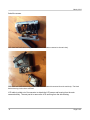
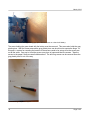
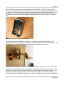
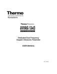
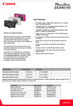
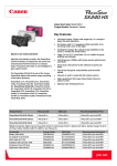
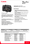
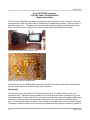
March, 2012
Sony DCR-SX40 Camcorder
LCD Flex Cable (“Flexible Board”)
Replacement Notes
The LCD of our DCR-SX40 camcorder went white after only three years of use. A search of the web
indicated that the LCD flex ribbon cable or “flexible board” needed to be replaced. These are notes of
what was done to fix it. The replacement flex cable was ordered on eBay from g-plustrading, Hong
Kong. The cable came, by regular mail, in about a week and a half to Vancouver, Canada.
DCR-SX40 functioning but with a white screen
A new LCD flex cable aka “flexible board”
A search of the web for “Flexible Board” and “Service Manual” turned up some helpful information as
well as a repair manual for an earlier model Sony camcorder.
Disassemble
The first step was to remove the LCD side camcorder housing. The bottom black housing was
removed as well. The bottom housing needs to be removed since the space is needed to plug in the
small ribbon cable. Be aware that there is one very short screw which goes in the battery slide-in area
and one very long course threads screw that (I think) goes in the upper hole of the battery slide in
area. The housing falls apart very easily. If the housing is not coming apart a screw has been missed.
The battery needs to be taken out and all the doors (power door and expansion card door) opened to
v3
Page 1 of 5
March, 2012
find all the screws.
DCR-SX40 with LCD side housing removed and LCD flex cable connected to the main body
DCR-SX40 with LCD side housing removed and LCD flex cable disconnected from the main body. The black
bottom housing is also shown removed.
LCD cable is pulled out of its connector to detach the LCD screen and housing from the main
camcorder body. The next part is to remove the LCD and hing from the side housing.
v3
Page 2 of 5
March, 2012
DCR-SX40 LCD side housing showing gray piece and the screw on a board with battery
The screw holding the green board with the battery must be removed. This screw also holds the gray
plastic piece. With the screw removed the gray plastic piece can be slid out to expose the hinge. At
this point, a system for recording the location of the screws needs to be set-up since the screws are
not all the same. One way is to set the screws on a piece of paper and label the screws. Tape the
screws to the paper if there are small children about. The two hing screws can be removed since the
gray plastic piece is out of the way.
Screw labeling on a piece of paper
v3
Page 3 of 5
March, 2012
The LCD has two screws on the inner side that need to be removed. The LCD is rotated to gain
access to remove the screws. The LCD panel back comes off by carefully prying the sides apart from
the hing end. Once the LCD back is off the hing is exposed and so is the flex cable connector. The
black bar on the flex cable connector flips up so the flex cable can be easily removed. Also, of course,
the new cable can be inserted and the black bar flipped down when it is time to insert the new flex
cable.
DCR-SX40 LCD panel housing inside view
The hinge housing is held together by a magnet , a small screw and is clipped together on the
opposite side. The very short hinge housing screw can be removed and the housing separated. Once
the hing housing is separated and removed the flex cable wrapped hing is exposed.
DCR-SX40 LCD hing with flex cable attached. To the left is the LCD side and to the right is the camcorder side
Take note as to how the ribbon cable is on the hing. The cable is wrapped around the hing one and a
half times. Be careful when removing the black clip on the LCD side of the cable (not shown). The
flex cable is stuck with sticky glue to the camcorder side of the hinge. The cable can be carefully
pulled off the hing so that the sticky glue can be re-used when attaching the new cable. Dis-assembly
v3
Page 4 of 5
March, 2012
is complete.
Assembly
The new cable must be folded in the same way as the old cable. The old cable can be used as a
guide and it can be partially unfolded to see how it is folded. The new cable comes attached with tape
which holds it together during folding. Fold the cable at the camcorder connector end in order to fold
the three strands over top of each other. Also, as a guide a bent paper clip (the same one used to
reset the camcorder as a troubleshooting step) can be put through the holes on the cable so the cable
strands line up as the strands are stuck together with the cable attached tape. Once the first side of
the cable is folded, essentially the same thing is done to fold the LCD side of the cable. The bent
paper clip and the holes (two sets) on the other side of the cable can be used to guide the cable
strands during folding.
Once the cable is formed it is stuck on to the the hing (as pictured above), wrapped around the hinge
two and a half times and the black clip is clipped on over the cable attaching it to the hinge.
Order of assembly is important to get the hing and hing housing in place. First the camcorder side of
the hing is placed into the side housing with the flex cable going through first. The hing is not screwed
in place at this point. Next the hinge housing is attached to the hinge by sliding each piece into place.
The black piece goes on the inside (LCD and controls side) and the silver/coloured piece goes on the
outside of the hinge. The hing housing can be screwed together now as the hole for the short screw is
accessible. Next, screw the hing into the camcorder housing. The LCD panel can now be assembled.
Locate the flex cable connector, flip up the black part of the connector, laying the flex cable end into
the connector and close the black part of the connector. The next step is to carefully snap the LCD
back housing on to the LCD panel. The two screws on the side of the LCD panel can be screwed in
with the LCD panel being twisted as necessary to access the screws. On the camcorder side, the
gray plastic piece needs to be put in place by going around the flex cable and sliding it into its place
which hides the hing. The green board with the gray piece's hole under it can be screwed down next.
Close the LCD panel to see how the flex cable will fit inside the camcorder. Locate the bump on the
gray plastic piece and a bump on the neighbouring housing. The two holes on the flex cable are
placed on the two bumps on the housing and gray piece. The flex cable is taped down with the bumps
in the holes using the tape that is fastened to the flex cable. The flex cable end can now be pressed
into the connector on the board and the side housing put into place by holding the pieces together with
one hand. The small flex cable at the bottom of the camcorder needs to be pressed into its connector
and then the black bottom housing can be put in place. The pieces can be held together by holding
them in one hand. Now, all the housing screws can be screwed in. Remember that screws go behind
the power connector door and the expansion card door. Once all the screws are in slide in the battery.
Test the camcorder operation. For me it worked!
I didn't time this job very well but I think it took me about three hours to replace the flex cable. I was
taking pictures and figuring out what to do along the way. It took about one hour to disassemble and
two hours to assemble. With these notes it would take less time. Perhaps an hour and a half.
These notes are provided as is. There is no guarantee that following these notes will fix a camcorder. There
may be typographical errors or omissions in these notes.
v3
Page 5 of 5