1
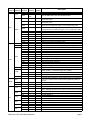
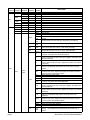
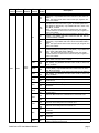
Studio Color 575 Addendum
Overview
This addendum replaces the menu map and menu item descriptions listed in Chapter 3 of the Studio
Color® User’s Manual (p/n 60600061). With the addition of preset programming for stand alone
operation, new options have been added to the Studio Color menu map. See individual subsections in
this addendum for descriptions of each menu item and for preset programming information.
Menu Map
Menu
Level 1
ADDR
Menu
Level 2
Menu
Level 3
Menu
Level 4
Fxx/Cxxx
LAMP
L/HR
L/ST
VER
L/RS
F/HR
F/RS
CURR
MINT
TEMP
MAXT
RST
INFO
DMX
FIXT
ERRS
FE
OV
CE
STRT
PANH
PANL
TLTH
TLTL
COLC
COL
CYAN
MAGN
YELW
LENS
FRST
SHUT
DIM
MSPD
CNTL
Menu
Level 5
Description
change the existing fixture number/DMX start channel
view whether the lamp is on (“L ON”), off (“LOFF”), attempting to
strike (“STRK”), or experiencing an error (“ERR”)
view the current number of lamp hours
view the current number of lamp strikes
view the fixture’s software version
reset lamp hours to zero (press and hold the <Enter> button for 5
seconds to zero the value)
view the current number of fixture hours
reset fixture hours to zero (press and hold the <Enter> button for 5
seconds to zero the value)
view the fixture’s current internal temperature (C)
view the fixture’s minimum internal temperature (C) reached since
this option was reset
view the fixture’s maximum internal temperature (C) reached since
this option was reset
reset the fixture’s minimum and maximum temperature values
view the total number of DMX errors
view the number of DMX framing errors
view the number of DMX overruns
view the DMX checksum errors
view the DMX start code value
view the DMX high resolution pan value
view the DMX low resolution pan value
view the DMX high resolution tilt value
view the DMX low resolution tilt value
view the DMX color control value
view the DMX fixed color wheel position value
view the DMX cyan color wheel position value
view the DMX magenta color wheel position value
view the DMX yellow color wheel position value
view the DMX lens wheel position value
view the DMX frost wheel position value
view the DMX shutter strobe value
view the DMX shutter dim flag value
view the DMX MSpeed time value
view the DMX control channel value
p/n 60600138 v. 1.0
Menu
Level 1
Menu
Level 2
Menu
Level 3
FIXT
DMX
DATA
Menu
Level 4
CSUM
C001 C512
SENP
SENT
SEN1
INFO
SENS
SEN2
SVCC
TIME
PCOR
TCOR
DUTY
PPOS
TPOS
HOME
S/UP
SELF
TEST
ALL
PAN
TILT
COLR
MAGN
YELW
CYAN
LENS
FRST
SHUT
DIM
BOOT
STAT
LAMP
LOFF
L ON
DISP
XLD
MODE
TYPE
FACT
CHNL
SET
DSPL
D/IN
P/IN
T/IN
SPOT
COLR
ON
OFF
DMX
ADDR
ON
OFF
DIM
ON
OFF
ON
OFF
ON
OFF
Studio Color ® 575 User’s Manual Addendum
Menu
Level 5
Description
view the DMX checksum value
view the DMX data for the selected DMX channel
view whether the pan sensor is obstructed (“OFF”) or is not
obstructed (“ON”)
view whether the tilt sensor is obstructed (“OFF”) or is not
obstructed (“ON”)
displays whether the fixed color wheel, cyan color wheel, and lens
wheel sensor is obstructed (“OFF”) or is not obstructed (“ON”)
displays whether the magenta color wheel, yellow color wheel, and
frost wheel sensor is obstructed (“OFF”) or is not obstructed (“ON”)
displays whether sensor is receiving power
Factory use only
displays the number of pan encoder corrections
displays the number of tilt encoder corrections
displays the duty cycle and phase of the pan and tilt encoders (%)
displays the encoder’s pan position value
displays the encoder’s tilt position value
home the fixture
place the fixture in setup mode for mechanical homing
self test all constructs
self test pan movement
self test tilt movement
self test fixed color wheel movement
self test magenta color wheel movement
self test yellow color wheel movement
self test cyan color wheel movement
self test lens wheel movement
self test frost wheel movement
self test shutter strobe movement
self test dim flag movement
copy the boot sector
view whether the lamp is on (“L ON”), off (“LOFF”), attempting to
strike (“STRK”), or is experiencing an error (“ERR”)
extinguish the lamp
strike the lamp
self test LED display
crossload fixture software to all other Studio Color 575, Studio Spot
575, ES-1, and EC-1 fixtures (with preset programming ability) on
the link
set the fixture type to Studio Spot 575
set the fixture type to Studio Color 575
set factory defaults on
set factory defaults off
Note: Selecting this option has no effect on individual preset values
set control method to DMX start channel
set control method to fixture number
set LED display on
set LED display off
dim LED display
invert LED display orientation
set normal LED display orientation
set pan invert on
set pan invert off
set tilt invert on
set tilt invert off
page 2
Menu
Level 1
Menu
Level 2
SWAP
S/DN
SET
LAMP
BOOT
CODE
PLAY
Menu
Level 3
Menu
Level 4
Menu
Level 5
ON
OFF
5 MN
10MN
L ON
LOFF
OFF
ON
SCN
SHUT
DIM
PAN
TILT
OPEN
CLSD
P001 P120
N001 N120
D000 D255
–185° +185°
–112.5° +112.5°
CN
FS
RS
LK
PRST
EDIT
SN01 SN16
2CN
COLC
2FS
2RS
2LK
M CN
M FS
M RS
M LK
M2CN
M2FS
M2RS
M2LK
COL
page 3
D000 D358
Description
set pan/tilt swap on
set pan/tilt swap off
set shutdown time for 5 minutes
set shutdown time for 10 minutes
strike the lamp
extinguish the lamp
copy the boot sector
Factory use only
set preset playback off
set preset playback on
display which scene is currently playing
open shutter
close shutter
periodic shutter strobe at specified intervals, slow (P001) to fast
(P120)
shutter strobe at random intervals, slow (N001) to fast (N120)
select a dim value from dark (D000) to bright (D255)
select a pan value from -185° to +185° of the pan range
D
select a tilt value from -112.5° to +112.5° of the tilt range
allows continuous positioning at any point on the fixed, cyan,
magenta, and yellow color wheels (full speed)
allows either a forward spin of the fixed color wheel or a variable
speed, red-green-blue cycle of the cyan, magenta, and yellow color
wheels (full speed)
allows either a reverse spin of the fixed color wheel or a variable
speed, random cycle of the cyan, magenta, and yellow color wheels
(full speed)
allows indexed positioning of the fixed color wheel so that the wheel
takes the quickest path and snaps to the center of the color (full
speed)
same as a COLC value of CN, but allows up to 2 continuous
rotations of the cyan, magenta, and yellow color wheels to allow a
choice of path to the specified position
same as a COLC value of FS
same as a COLC value of RS
same as a COLC value of LK
allows continuous positioning at any point on the fixed, cyan,
magenta, and yellow color wheels (MSpeed)
allows either a forward spin of the fixed color wheel or a variable
speed, red-green-blue cycle of the cyan, magenta, and yellow color
wheels (MSpeed)
allows either a reverse spin of the fixed color wheel or a variable
speed, random cycle of the cyan, magenta, and yellow color wheels
(MSpeed)
allows indexed positioning of the fixed color wheel so that the wheel
takes the quickest path and snaps to the center of the color
(MSpeed)
same as a COLC value of M CN, but allows up to 2 continuous
rotations of the cyan, magenta, and yellow color wheels to allow a
choice of path to the specified position
same as a COLC value of M FS
same as a COLC value of M RS
same as a COLC value of M LK
select a color wheel position in degrees from 0° (D000) to 358°
(D358) - only available with COLC value of CN, 2CN, M CN, or
M2CN.
Studio Color ® 575 User’s Manual Addendum
Menu
Level 1
Menu
Level 2
Menu
Level 3
Menu
Level 4
Menu
Level 5
F001 F124
M001 M128
COL
STIL
R001 R124
N001 N128
C 0C 5
PRST
EDIT
SN01 SN16
CYAN
D000 D358
MAGN
D000 D358
YELW
D000 D358
LENS
FRST
MSPD
XFAD
DLAY
OPEN
D001 D357
OPEN
D001 D355
NONE
0.15 252.7
X 0.1 X 9.9
X 10 X166
D 0.1 D 9.9
D 10 D166
SEC
TIME
MIN
HOUR
ZERO
Studio Color ® 575 User’s Manual Addendum
OK?
Description
select a fixed color wheel forward spin speed from slow (F001) to
fast (F124) - only available with COLC value of FS, 2FS, M FS, or
M2FS
Note: This option allows direct control of the cyan, magenta, and
yellow color wheels
cycle the cyan, magenta, and yellow color wheels through 9 factoryselected colors from red to blue to green at variable speeds from
slow (M001) to fast (M128) - only available with COLC value of FS,
2FS, M FS, or M2FS
Note: This option sets the fixed color wheel to the open “white”
position and does not allow direct control of the cyan, magenta, or
yellow color wheels
stop any color wheel spin and move all wheels to the open “white”
position - only available with COLC value of FS, RS, 2FS, 2RS, M
FS, M RS, M2FS, or M2RS
select a fixed color wheel reverse spin speed from slow (R001) to
fast (R124) - only available with COLC value of RS, 2RS, M RS or
M2RS
Note: This option allows direct control over the cyan, magenta, and
yellow color wheels
randomly cycle the cyan, magenta, and yellow color wheels at
variable speeds from slow (N001) to fast (N128) - only available with
COLC value of RS, 2RS, M RS or M2RS
Note: This option sets the fixed color wheel to the open “white”
position and does not allow direct control of the cyan, magenta, or
yellow color wheels
select a fixed color wheel, full color position - only available with
COLC value of LK, 2LK, M LK, or M2LK
select an exact position on the cyan color wheel from 0° (D000) to
358° (D358) - only available with COLC value of CN, LK, 2CN, 2LK,
M CN, or M2CN
select an exact position on the magenta color wheel from 0° (D000)
to 358° (D358) - only available with COLC value of CN, LK, 2CN,
2LK, M CN, or M2CN
select an exact position on the yellow color wheel from 0° (D000) to
358° (D358) - only available with COLC value of CN, LK, 2CN, 2LK,
M CN, or M2CN
select the open (no lens) position on the lens wheel
select a specific lens wheel position on either the radium, lenticular,
or fibroid lens
select the open (no lens) position on the frost wheel
select a specific frost wheel position on either the frost, lenticular, or
fibroid lens
disable MSpeed and allow for DMX controller crossfade
select a motor movement time in decimal seconds, from fast (0.15)
to slow (252.7)
select the DIM construct’s crossfade time in increments of 0.1
select the DIM construct’s crossfade time in increments of 1
select the scene delay time in increments of 0.1
select the scene delay time in increments of 1
select seconds as the units of time used for the XFAD and DLAY
constructs
select minutes as the units of time used for the XFAD and DLAY
constructs
select hours as the units of time used for the XFAD and DLAY
constructs
erase any programming of the current scene by voiding all construct
values / mark the end of the loop
page 4
Menu
Level 1
Menu
Level 2
Menu
Level 3
FROM
COPY
TO
PRST
CAPT
SN01 SN16
DFLT
OK?
Menu
Level 4
Menu
Level 5
F 01 F 16
T 01 T 16
Description
select a scene to copy from (source scene)
select a scene to copy to (destination scene)
select a scene to capture a pre-programmed scene to (from your
DMX controller)
enable the factory-programmed 16 preset scene sequence - erases
any preset scenes previously programmed
Menu Options
The sections below explain how to access the fixture options shown in the fixture’s menu map. For more
information on preset programming, see page 19.
Address Menu (ADDR)
D
Use the Address menu to quickly change the current fixture number/DMX start channel. Using this menu
option, you can only change the existing fixture number to another fixture number, or the existing DMX
start channel to another DMX start channel.
If you want to change the way you identify the fixture (i.e. change to a fixture number instead of a DMX
start channel, or vice versa), complete the procedure described in "Setting the Fixture Shutdown Time
(S/DN)" on page 16.
To change the current fixture number or DMX start channel:
1. Press and hold the <Menu> button until “ADDR” appears on the LED display.
2. Press the <Enter> button to select the “ADDR” menu.
3. Use the <Up> and <Down> arrow buttons to select a new DMX start channel (C001 - C512)
/ fixture number (F 01 - F xx). The LED display will flash when a new option is selected.
or
4. Press the <Enter> button to accept the new fixture number / DMX start channel. The LED
display will stop flashing when a new option is entered. If you do not press the <Enter>
button, the new option you selected will not be stored.
Note:
Be sure you do not overlap fixture channel ranges when changing the fixture number/
DMX start channel.
Information Menu (INFO)
The Information menu allows you to view current fixture information such as lamp status, lamp hours,
lamp strikes, software version, total fixture hours, internal temperature, sensor information, DMX errors,
and DMX data for any other device on the link. You can also reset the lamp hours or fixture hours. The
procedures below are listed in the order that they appear on the menu map.
page 5
Studio Color ® 575 User’s Manual Addendum
Viewing the Lamp Status (LAMP)
This menu option allows you to view the fixture’s current lamp status.
To view the lamp status:
1. Press and hold the <Menu> button until “ADDR” appears on the LED display.
2. Using the <Up> and <Down> arrow buttons, scroll to the “INFO” menu and press the
<Enter> button to select the “INFO” menu.
3. Using the <Up> and <Down> arrow buttons, scroll to the “LAMP” option. (This will be the
first option displayed.) Press the <Enter> button to select the “LAMP” option. The LED will
display “L ON” if the lamp is on, “LOFF” if the lamp is off, “STRK” if the lamp is attempting to
strike, or “ERR” if the lamp is experiencing an error.
Viewing the Current Lamp Hours (L/HR)
To view the number of hours the lamp has been on since this option was reset:
1. Press and hold the <Menu> button until “ADDR” appears on the LED display.
2. Using the <Up> and <Down> arrow buttons, scroll to the “INFO” menu and press the
<Enter> button to select the “INFO” menu.
3. Using the <Up> and <Down> arrow buttons, scroll to the “L/HR” option and press the
<Enter> button to select the “L/HR” option. The LED will display the number of hours the
lamp has been on since this option was reset.
Viewing the Number of Current Lamp Strikes (L/ST)
To view the number of times the fixture has attempted to strike (turn on) the current lamp:
1. Press and hold the <Menu> button until “ADDR” appears on the LED display.
2. Using the <Up> and <Down> arrow buttons, scroll to the “INFO” menu and press the
<Enter> button to select the “INFO” menu.
3. Using the <Up> and <Down> arrow buttons, scroll to the “L/ST” option and press the
<Enter> button to select the “L/ST” option. The LED will display the number of times the
fixture has struck the current lamp.
Note:
Lamp strikes are automatically reset when the lamp hours are reset (see “Resetting Lamp
Hours (L/RS)” below).
Viewing the Current Software Version (VER)
To view the current software version:
1. Press and hold the <Menu> button until “ADDR” appears on the LED display.
2. Using the <Up> and <Down> arrow buttons, scroll to the “INFO” menu and press the
<Enter> button to select the “INFO” menu.
3. Using the <Up> and <Down> arrow buttons, scroll to the “VER” option and press the
<Enter> button to select the “VER” option. The LED will display the fixture’s current
software version.
Note:
The software version is also displayed when you exit the menu system and the normal
alphanumeric display cycles between displaying the software version, the fixture name,
and the fixture address.
Studio Color ® 575 User’s Manual Addendum
page 6
Resetting Lamp Hours (L/RS)
This menu item allows you to track the number of hours the current lamp has been operating.
To reset the current lamp hours to zero:
1. Press and hold the <Menu> button until “ADDR” appears on the LED display.
2. Using the <Up> and <Down> arrow buttons, scroll to the “INFO” menu and press the
<Enter> button to select the “INFO” menu.
3. Using the <Up> and <Down> arrow buttons, scroll to the “L/RS” option and press the
<Enter> button to select the “L/RS” option*. The LED will display “0000” when the lamp
hours are reset.
*Note:
This option has a 5-second delay to avoid inadvertent changes. To reset the lamp hours,
you must press and hold the <Enter> button for at least 5 seconds.
Viewing the Current Fixture Hours (F/HR)
To view the number of hours the fixture has been on since this option was reset:
1. Press and hold the <Menu> button until “ADDR” appears on the LED display.
2. Using the <Up> and <Down> arrow buttons, scroll to the “INFO” menu and press the
<Enter> button to select the “INFO” menu.
D
3. Using the <Up> and <Down> arrow buttons, scroll to the “F/HR” option and press the
<Enter> button to select the “F/HR” option. The LED will display the number of hours the
fixture has been on since this option was reset.
Resetting Fixture Hours (F/RS)
This menu item allows you to track the number of hours the fixture has been operating.
To reset the fixture hours to zero:
1. Press and hold the <Menu> button until “ADDR” appears on the LED display.
2. Using the <Up> and <Down> arrow buttons, scroll to the “INFO” menu and press the
<Enter> button to select the “INFO” menu.
3. Using the <Up> and <Down> arrow buttons, scroll to the “F/RS” option and press the
<Enter> button to select the “F/RS” option*. The LED will display “0000” when the fixture
hours are reset.
*Note:
This option has a 5-second delay to avoid inadvertent changes. To reset the fixture hours,
you must press and hold the <Enter> button for at least 5 seconds.
Viewing the Logic Board Temperature (TEMP)
This menu option allows you to view the logic board’s current, minimum, and maximum temperatures.
This option also allows you to reset the minimum and maximum temperature readings.
To view the logic board temperatures:
1. Press and hold the <Menu> button until “ADDR” appears on the LED display.
2. Using the <Up> and <Down> arrow buttons, scroll to the “INFO” menu and press the
<Enter> button to select the “INFO” menu.
3. Using the <Up> and <Down> arrow buttons, scroll to the “TEMP” option and press the
<Enter> button to select the “TEMP” option.
page 7
Studio Color ® 575 User’s Manual Addendum
or
4. Using the <Up> and <Down> arrow buttons, scroll to the “CURR” option to view the
current temperature, “MINT” to view the minimum temperature, “MAXT” to view the
maximum temperature, or “RST” to reset the minimum and maximum temperature readings.
or
5. Press the <Enter> button to select the desired option. The LED will display the temperature
of the fixture’s logic board in degrees centigrade.
or
The maximum temperature reading for the logic board is 99° C. If this maximum temperature
is exceeded, the fixture will shut down and the LED panel will display “OVER TEMP.”
Viewing DMX Status and Construct Values (FIXT)
This menu option allows you to view DMX status and construct values for the fixture. You should follow
this procedure if you are having a particular problem with a fixture; for example, a color wheel that does
not respond to commands from the controller.
The following DMX status information is available for viewing:
• ERRS - total number of DMX errors
• FE - number of framing errors
• OV - overruns (changing values could indicate data link/connector problems)
• CE - DMX checksum errors
• STRT - start code
The following construct values are available for viewing:
• PANH - high 8-bit pan value
• PANL - low 8-bit pan value
• TLTH - high 8-bit tilt value
• TLTL - low 8-bit tilt value
• COLC - color control value
• COL - color wheel position value
• CYAN - cyan color wheel position value
• MAGN - magenta color wheel position value
• YELW - yellow color wheel position value
• LENS - lens wheel position value
• FRST - frost wheel position value
• SHUT - shutter strobe value
• DIM - shutter dim flag value
• MSPD - MSpeed time value
• CNTL - control channel value
• CSUM - DMX checksum value
To view the DMX status and construct values:
1. Press and hold the <Menu> button until “ADDR” appears on the LED display.
2. Using the <Up> and <Down> arrow buttons, scroll to the “INFO” menu and press the
<Enter> button to select the “INFO” menu.
3. Using the <Up> and <Down> arrow buttons, scroll to the “DMX” menu and press the
<Enter> button to select the “DMX” menu.
4. Using the <Up> and <Down> arrow buttons, scroll to the “FIXT” menu and press the
<Enter> button to select the “FIXT” menu.
5. Using the <Up> and <Down> arrow buttons, scroll to the desired DMX status or construct
(listed above) and press the <Enter> button to select the desired option. The LED will
display the selected DMX status or construct value.
Studio Color ® 575 User’s Manual Addendum
page 8
If you are having a particular problem with the fixture, follow the steps above to select a construct and
view its value. After noting the value of the construct you selected, use your controller to change that
construct’s value.
If the value changes on the fixture’s LED display, but the fixture still does not respond, contact High End
Systems customer service.
However, if the value does not change on the fixture’s LED display, remove the fixture from the DMX link
and try to change the construct’s value using the fixture’s menu system. If the fixture then functions
normally, the problem was likely with the DMX link. Otherwise, contact High End Systems customer
service.
Viewing DMX Data for Another Device (DATA)
This procedure allows you to use a Studio Spot 575 or Studio Color 575 fixture to view DMX channel
values for other devices on the DMX link. You should use this procedure either for testing devices that do
not have built-in DMX diagnostics, or for fixtures that are physically inconvenient to monitor directly.
To view DMX data for another device on the DMX link:
1. Press and hold the <Menu> button until “ADDR” appears on the LED display.
2. Using the <Up> and <Down> arrow buttons, scroll to the “INFO” menu and press the
<Enter> button to select the “INFO” menu.
D
3. Using the <Up> and <Down> arrow buttons, scroll to the “DMX” menu and press the
<Enter> button to select the “DMX” menu.
4. Using the <Up> and <Down> arrow buttons, scroll to the “DATA” menu and press the
<Enter> button to select the “DATA” menu.
to
5. Using the <Up> and <Down> arrow buttons, scroll to the desired DMX channel (C001 C512) and press the <Enter> button to select the desired DMX channel. The LED will
display the selected channel’s DMX value.
If you are experiencing a particular problem with a device on the link, follow the steps above to select a
DMX channel in the device’s channel range and view its DMX value. After noting the value of the
channel you selected, use your controller to change that channel’s value.
If the value of the DMX channel you selected does not change, there may be a problem with the DMX
cable or your transmitting device (i.e. controller).
However, if the DMX channel value changes, but the device does not respond, the device may be faulty.
Consult the documentation provided with that device for more information.
Viewing Sensor Information (SENS)
This menu option allows you to view whether a specified sensor if working correctly. If you receive a
“SENS ERR” error message on the LED display, this information may help you determine where the
problem originates.
The following sensor information is available:
• SENP - view whether the pan sensor is obstructed (“OFF”) or is not obstructed (“ON”)
• SENT - view whether the tilt sensor is obstructed (“OFF”) or is not obstructed (“ON”)
• SEN1 - view whether the fixed color wheel, cyan color wheel, and lens wheel sensor is obstructed
(“OFF”) or is not obstructed (“ON”)
• SEN2 - view whether the magenta color wheel, yellow color wheel, and frost wheel sensor is
obstructed (“OFF”) or is not obstructed (“ON”)
• SVCC - view whether the sensor is receiving power (“ON”) or is not receiving power (“OFF”)
page 9
Studio Color ® 575 User’s Manual Addendum
•
•
•
•
•
•
TIME - Factory use only
PCOR - view the number of pan encoder corrections
TCOR - view the number of tilt encoder corrections
DUTY - view the duty cycle and phase of the pan and tilt encoders (this information is displayed
as a percentage and is normally ± 10% of 50)
PPOS - view the encoder’s pan position value represented as a number of encoder “counts”
TPOS - view the encoder’s tilt position value represented as a number of encoder “counts”
To view the specified sensor information:
1. Press and hold the <Menu> button until “ADDR” appears on the LED display.
2. Using the <Up> and <Down> arrow buttons, scroll to the “INFO” menu and press the
<Enter> button to select the “INFO” menu.
3. Using the <Up> and <Down> arrow buttons, scroll to the “SENS” menu and press the
<Enter> button to select the “SENS” menu.
4. Using the <Up> and <Down> arrow buttons, scroll to the desired sensor option (listed
above) and press the <Enter> button to select the desired option to view its sensor
information.
Test Menu (TEST)
The Test menu allows you to manually home the fixture, place the fixture in setup mode, perform fixture
self tests, store new boot code information, and manually turn the lamp on or off. If you are experiencing
problems that you suspect are mechanical, performing fixture self tests will help to determine where the
problem lies. The procedures below are listed in the order that they appear on the menu map.
Note:
To see the effects of the self tests, the lamp must be on. If the lamp is off when you run the
self test, the LED will display “STRK” to indicate that the lamp is not struck, and the fixture
will attempt to strike the lamp automatically.
Homing the Fixture (HOME)
To manually home the fixture:
1. Press and hold the <Menu> button until “ADDR” appears on the LED display.
2. Using the <Up> and <Down> arrow buttons, scroll to the “TEST” menu and press the
<Enter> button to select the “TEST” menu.
3. Using the <Up> and <Down> arrow buttons, scroll to the “HOME” option. (This will be the
first option displayed.)
4. Press the <Enter> button to select the “HOME” option. The LED will alternately display
“RST” and “HOME” while the fixture homes.
Placing the Fixture in Setup Mode (S/UP)
This menu item allows you to place the fixture in setup mode so that you can mechanically home your
fixture. A fixture that is out of home (i.e., the dim flags lose position), will emit an unusually loud clicking
noise when strobing or electronically homing. For more information on how to mechanically home the
fixture, contact High End Systems customer service.
To place the fixture in setup mode:
1. Press and hold the <Menu> button until “ADDR” appears on the LED display.
Studio Color ® 575 User’s Manual Addendum
page 10
2. Using the <Up> and <Down> arrow buttons, scroll to the “TEST” menu and press the
<Enter> button to select the “TEST” menu.
3. Using the <Up> and <Down> arrow buttons, scroll to the “S/UP” option and press the
<Enter> button to select the “S/UP” option.
4. When the LED displays “SET NOW,” mechanically home the fixture.
5. After mechanically homing the fixture, press any button. This causes the fixture to
electronically home.
Performing Self Tests (SELF)
This menu item performs the appropriate self tests for the following:
•
•
•
•
•
•
•
•
•
•
•
ALL - performs all of the self tests listed below
PAN - tests the pan motor movement
TILT - tests the tilt motor movement
COLR - tests fixed color wheel movement
MAGN - tests magenta color wheel movement
YELW - tests yellow color wheel movement
CYAN - tests cyan color wheel movement
LENS - tests lens wheel movement
FRST - tests frost wheel movement
SHUT - tests strobe functions
DIM - tests dim flag movement
D
To perform a self test:
1. Press and hold the <Menu> button until “ADDR” appears on the LED display.
2. Using the <Up> and <Down> arrow buttons, scroll to the “TEST” menu and press the
<Enter> button to select the “TEST” menu.
3. Using the <Up> and <Down> arrow buttons, scroll to the “SELF” menu and press the
<Enter> button to select the “SELF” menu.
4. Using the <Up> and <Down> arrow buttons, scroll to the desired option (listed above).
Press the <Enter> button to select the desired option. The fixture will perform the selected
self test.
5. Press the <Menu> button to exit the test.
Note:
The self tests will run continuously until you press the <Menu> button to exit the test.
Copying the Boot Code (BOOT)
When you upload new software to Studio Color 575 fixtures, the new software may contain a new boot
code which must be copied to each fixture. This is apparent if the LED displays a “BOOT DIFF” error.
Do not remove power from the fixture while performing a boot copy. You can copy the new boot code
using either the TEST menu or the SET menu.
To accept and store the new boot code using the TEST menu:
1. Press and hold the <Menu> button until “ADDR” appears on the LED display.
2. Using the <Up> and <Down> arrow buttons, scroll to the “TEST” menu and press the
<Enter> button to select the “TEST” menu.
3. Using the <Up> and <Down> arrow buttons, scroll to the “BOOT” option and press the
<Enter> button to select the “BOOT” option. The fixture will store the new boot code, then
automatically home.
page 11
Studio Color ® 575 User’s Manual Addendum
Turning the Lamp On or Off (LAMP)
You can manually turn the lamp on and off using either the TEST menu or the SET menu.
To manually turn the lamp on or off via the TEST menu:
1. Press and hold the <Menu> button until “ADDR” appears on the LED display.
2. Using the <Up> and <Down> arrow buttons, scroll to the “TEST” menu and press the
<Enter> button to select the “TEST” menu.
3. Using the <Up> and <Down> arrow buttons, scroll to the “LAMP” menu and press the
<Enter> button to select the “LAMP” menu.
4. Using the <Up> and <Down> arrow buttons, choose the “ON” option to strike the lamp, the
“OFF” option to extinguish the lamp, or the “STAT” option to view the lamp status (for
information on lamp status options, see "Viewing the Lamp Status (LAMP)" on page 6.
5. Press the <Enter> button to select the desired option.
Testing the LED Display (DISP)
To perform a self-test on the LED display:
1. Press and hold the <Menu> button until “ADDR” appears on the LED display.
2. Using the <Up> and <Down> arrow buttons, scroll to the “TEST” menu and press the
<Enter> button to select the “TEST” menu.
3. Using the <Up> and <Down> arrow buttons, scroll to the “DISP” option and press the
<Enter> button to select the “DISP” option. The LED will run through its self test.
4. Press the <Menu> button to exit the test.
Note:
The self test will run continuously until you press the <Menu> button to exit the test.
Mode Menu (MODE)
The Mode menu allows you to set the fixture type to either Studio Spot 575 or Studio Color 575 and
crossload software versions from one fixture to all other Studio Spot 575 or Studio Color 575 fixtures on
the link. The procedures below are listed in the order that they appear on the menu map.
Crossloading Fixture Software (XLD)
Studio Color 575, Studio Spot 575, ES-1, and EC-1 fixtures (with preset programming ability) use the
same software. Therefore, if you have a fixture with a newer software version, you can crossload the
newer software to all other Studio Color 575, Studio Spot 575, ES-1, and EC-1 fixtures on the link.
To crossload software:
1. Disconnect or bypass any controllers, serial data distributors, data line optoisolators, and any
fixtures using RS-422 communications (such as Dataflash® AF1000 xenon strobes,
Intellabeam® fixtures, and Emulator® laser simulators). These devices will block
communication between your crossloading fixture and any other Studio Color 575, Studio
Spot 575, EC-1, or ES-1 fixtures on the link.
2. On the crossloading fixture only, press and hold the <Menu> button until “ADDR” appears on
the LED display.
3. Using the <Up> and <Down> arrow buttons, scroll to the “MODE” menu and press the
<Enter> button to select the “MODE” menu.
Studio Color ® 575 User’s Manual Addendum
page 12
4. Using the <Up> and <Down> arrow buttons, scroll to the “XLD” option and press the
<Enter> button to select the “XLD” option. The fixture will upload its software to all other
Studio Color 575, Studio Spot 575, ES-1, and EC-1 fixtures on the link.
The Transmit LED on the crossloading fixture will remain on (or flicker). The Transmit and Receive LEDs
on receiving fixtures will flicker while the crossload is in progress, and “UPLD” will appear on the
alphanumeric display as each fixture receives the software upload. When the crossload has finished
successfully, “DONE” will appear briefly in the LED display of the crossloading fixture, and all other
fixtures will home.
Note:
If a new boot code was included with the latest software, the LED will display a “BOOT
DIFF” error. To correct the boot code, you must copy the new boot code for each fixture
(see "Copying the Boot Code (BOOT)" on page 11).
Setting the Fixture Type (TYPE)
Use this menu item to change the fixture type to either Studio Spot 575 or Studio Color 575. All fixtures
are shipped from the factory set to the correct fixture type. However, if the fixture’s logic board is
replaced, you must ensure the new board is set to the correct fixture type.
To set the fixture type:
1. Press and hold the <Menu> button until “ADDR” appears on the LED display.
2. Using the <Up> and <Down> arrow buttons, scroll to the “MODE” menu and press the
<Enter> button to select the “MODE” menu.
D
3. Using the <Up> and <Down> arrow buttons, scroll to the “TYPE” menu. (This will be the
first menu displayed). Press the <Enter> button to select the “TYPE” menu.
4. Using the <Up> and <Down> arrow buttons, choose the “SPOT” option for Studio Spot 575
fixtures, or the “COLR” option for Studio Color 575 fixtures. Press the <Enter> button to
select the desired option.
or
Set Menu (SET)
The Set menu allows you to change the control method from a fixture number to a DMX start channel or
vice versa, and either set all factory options to their default settings or change the factory options
individually. The procedures below are listed in the order that they appear in the menu map.
Setting Factory Defaults (FACT)
Studio Color 575 fixtures are shipped from the factory with the following preset options set to the
following defaults:
•
•
•
•
•
•
pan/tilt swap = off
tilt invert = off
pan invert = off
LED display = on
LED display invert = off
shutdown = 5 min.
To return all preset options to their factory defaults settings:
1. Press and hold the <Menu> button until “ADDR” appears on the LED display.
2. Using the <Up> and <Down> arrow buttons, scroll to the “SET” menu and press the
<Enter> button to select the “SET” menu.
3. Using the <Up> and <Down> arrow buttons, scroll to the “FACT” menu. (This will be the
first menu displayed.) Press the <Enter> button to select the “FACT” menu.
page 13
Studio Color ® 575 User’s Manual Addendum
4. Using the <Up> and <Down> arrow buttons, choose “ON” to set the factory option defaults
on and press the <Enter> button to select the desired option.*
*Note: Although “OFF” is an available option in the FACT menu, selecting the “OFF” option will
have no effect on the individual preset values. To change the value of any of the individual
presets listed above, you must access each preset’s corresponding menu item. When you
change any of the preset default values individually, this menu item will automatically be
turned off.
Changing the Control Method (CHNL)
Use this menu item if your fixture is currently set to the fixture number control method and instead, you
want to use the DMX start channel control method, or vice versa. To simply change an existing fixture
number to a different fixture number (or DMX start channel to a different DMX start channel), see
"Address Menu (ADDR)" on page 5.
To change the control method:
1. Press and hold the <Menu> button until “ADDR” appears on the LED display.
2. Using the <Up> and <Down> arrow buttons, scroll to the “SET” menu and press the
<Enter> button to select the “SET” menu.
3. Using the <Up> and <Down> arrow buttons, scroll to the “CHNL” menu and press the
<Enter> button to select the “CHNL” menu.
or
4. Using the <Up> and <Down> arrow buttons, choose either the “DMX” option to address
the fixture using a DMX start channel, or the “ADDR” option to address the fixture using a
fixture number. Press the <Enter> button to select the desired option.
Note:
After changing the control method, you must assign a specific DMX start channel (C001 C512) or fixture number (F 01 - F xx) to each fixture (see "Address Menu (ADDR)" on
page 5).
Changing the Display Output (DSPL)
This menu item allows you to change the appearance of the fixture’s alphanumeric LED display. You can
set the display on or off, or you can dim the display to reduce visibility.
To change the display output:
1. Press and hold the <Menu> button until “ADDR” appears on the LED display.
2. Using the <Up> and <Down> arrow buttons, scroll to the “SET” menu and press the
<Enter> button to select the “SET” menu.
3. Using the <Up> and <Down> arrow buttons, scroll to the “DSPL” menu and press the
<Enter> button to select the “DSPL” menu.
4. Using the <Up> and <Down> arrow buttons, choose the “ON” option to set the LED display
to normal intensity, the “OFF” option to turn the LED display off, or the “DIM” option to
reduce the LED display visibility. Press the <Enter> button to select the desired option.
Note:
If you set the LED display off, the LED display will be turned off only when you exit the
menu system.
Studio Color ® 575 User’s Manual Addendum
page 14
Inverting LED Characters (D/IN)
This menu item allows you to invert the orientation of the LED display’s alphanumeric characters. This
option is useful if your fixture is standing upright (i.e., resting on its bottom panel on the floor).
To invert the LED display:
1. Press and hold the <Menu> button until “ADDR” appears on the LED display.
2. Using the <Up> and <Down> arrow buttons, scroll to the “SET” menu and press the
<Enter> button to select the “SET” menu.
3. Using the <Up> and <Down> arrow buttons, scroll to the “D/IN” menu and press the
<Enter> button to select the “D/IN” menu.
4. Using the <Up> and <Down> arrow buttons, choose the “ON” option to invert the fixture’s
alphanumeric characters, or the “OFF” option to return the fixture’s alphanumeric characters
to normal orientation. Press the <Enter> button to select the desired option.
Inverting Pan (P/IN)
To invert the direction of the fixture’s pan motion:
1. Press and hold the <Menu> button until “ADDR” appears on the LED display.
D
2. Using the <Up> and <Down> arrow buttons, scroll to the “SET” menu and press the
<Enter> button to select the “SET” menu.
3. Using the <Up> and <Down> arrow buttons, scroll to the “P/IN” menu and press the
<Enter> button to select the “P/IN” menu.
4. Using the <Up> and <Down> arrow buttons, choose the “ON” option to invert the fixture’s
pan motion, or the “OFF” option to return the fixture’s pan motion to normal orientation.
Press the <Enter> button to select the desired option.
Inverting Tilt (T/IN)
To invert the direction of the fixture’s tilt motion:
1. Press and hold the <Menu> button until “ADDR” appears on the LED display.
2. Using the <Up> and <Down> arrow buttons, scroll to the “SET” menu and press the
<Enter> button to select the “SET” menu.
3. Using the <Up> and <Down> arrow buttons, scroll to the “T/IN” menu and press the
<Enter> button to select the “T/IN” menu.
4. Using the <Up> and <Down> arrow buttons, choose the “ON” option to invert the fixture’s
tilt motion, or the “OFF” option to return the fixture’s tilt motion to normal orientation. Press
the <Enter> button to select the desired option.
Swapping Pan and Tilt (SWAP)
To swap the fixture’s pan and tilt motion:
1. Press and hold the <Menu> button until “ADDR” appears on the LED display.
2. Using the <Up> and <Down> arrow buttons, scroll to the “SET” menu and press the
<Enter> button to select the “SET” menu.
page 15
Studio Color ® 575 User’s Manual Addendum
3. Using the <Up> and <Down> arrow buttons, scroll to the “SWAP” menu and press the
<Enter> button to select the “SWAP” menu.
4. Using the <Up> and <Down> arrow buttons, choose the “ON” option to swap the fixture’s
pan and tilt motion, or the “OFF” option to return the fixture’s pan and tilt motion to normal
orientation. Press the <Enter> button to select the desired option.
Setting the Fixture Shutdown Time (S/DN)
Use this menu item to set the fixture to automatically shutdown (or deactivate) either 5 or 10 minutes
after DMX data is removed. When a fixture is in shutdown mode, the lamp is extinguished, power to the
motors is disabled, and the LED display is turned off. Once a fixture is in shutdown mode, you must
home the fixture to bring it back into operation.
To set fixture shutdown:
1. Press and hold the <Menu> button until “ADDR” appears on the LED display.
2. Using the <Up> and <Down> arrow buttons, scroll to the “SET” menu and press the
<Enter> button to select the “SET” menu.
3. Using the <Up> and <Down> arrow buttons, scroll to the “S/DN” menu and press the
<Enter> button to select the “S/DN” menu.
4. Using the <Up> and <Down> arrow buttons, choose the “5 MN” option to enable
shutdown after 5 minutes, or the “10MN” option to enable shutdown after 10 minutes. Press
the <Enter> button to select the desired option.
Turning the Lamp On or Off (LAMP)
You can manually turn the lamp on and off using either the TEST menu or the SET menu.
To turn the lamp on or off via the SET menu:
1. Press and hold the <Menu> button until “ADDR” appears on the LED display.
2. Using the <Up> and <Down> arrow buttons, scroll to the “SET” menu and press the
<Enter> button to select the “SET” menu.
3. Using the <Up> and <Down> arrow buttons, scroll to the “LAMP” menu and press the
<Enter> button to select the “LAMP” menu.
4. Using the <Up> and <Down> arrow buttons, choose the “ON” option to strike the lamp, the
“OFF” option to extinguish the lamp.
5. Press the <Enter> button to select the desired option.
Copying the Boot Code (BOOT)
When you upload new software to Studio Color 575 fixtures, the new software may contain a new boot
code which must be copied to each fixture. This is apparent if the LED displays a “BOOT DIFF” error.
Do not remove power from the fixture while performing a boot copy. You can copy the new boot code
using either the TEST menu or the SET menu.
To accept and store the new boot code using the SET menu:
1. Press and hold the <Menu> button until “ADDR” appears on the LED display.
2. Using the <Up> and <Down> arrow buttons, scroll to the “SET” menu and press the
<Enter> button to select the “SET” menu.
3. Using the <Up> and <Down> arrow buttons, scroll to the “BOOT” option and press the
<Enter> button to select the “BOOT” option. The fixture will store the new boot code, then
automatically home.
Studio Color ® 575 User’s Manual Addendum
page 16
Preset Menu (PRST)
The Preset menu allows you to turn preset playback off or on, view which scene is currently playing, and
create/edit a scene using the on-board memory to program the fixture for stand-alone operation. This
menu also allows you to copy a scene within the fixture’s on-board memory, capture a scene from your
DMX controller to the fixture’s on-board memory, and enable the fixture’s factory-programmed preset
sequence (self demo).
Setting Preset Playback (PLAY)
This menu option allows you to turn preset playback on or off and view which scene is currently playing
in preset playback mode.
To set preset playback on or off, or to view the current scene:
1. Press and hold the <Menu> button until “ADDR” appears on the LED display.
2. Using the <Up> and <Down> arrow buttons, scroll to the “PRST” menu. Press the
<Enter> button to select the “PRST” menu.
3. Using the <Up> and <Down> arrow buttons, scroll to the “PLAY” menu. (This will be the
first option displayed). Press the <Enter> button to select the “PLAY” menu.
4. Using the <Up> and <Down> arrow buttons, scroll to the “ON” option to set preset
playback on, the “OFF” option to set preset playback off, or the “SCN” option to display
which scene is currently playing. Press the <Enter> button to select the desired option.
Note:
D
Scene 1 must be programmed before the fixture can play back scenes.
Editing or Creating an On-Board Memory Scene (EDIT)
This menu item allows you to edit or create a scene using the fixture’s on-board scene memory. Using
this menu option, you can change the value of any construct in any of the on-board scenes. For detailed
information on editing or creating a scene, see "Preset Programming" on page 20.
To edit/create a scene:
1. Press and hold the <Menu> button until “ADDR” appears on the LED display.
2. Using the <Up> and <Down> arrow buttons, scroll to the “PRST” menu and press the
<Enter> button to select the “PRST” menu.
3. Using the <Up> and <Down> arrow buttons, scroll to the “EDIT” menu and press the
<Enter> button to select the “EDIT” menu.
to
4. Using the <Up> and <Down> arrow buttons, scroll to the scene (“SN01” to “SN16”) that
you want to edit or create and press the <Enter> button to select the desired scene.
Copying an On-Board Memory Scene (COPY)
1. Press and hold the <Menu> button until “ADDR” appears on the LED display.
2. Using the <Up> and <Down> arrow buttons, scroll to the “PRST” menu and press the
<Enter> button to select the “PRST” menu.
3. Using the <Up> and <Down> arrow buttons, scroll to the “COPY” menu and press the
<Enter> button to select the “COPY” menu.
4. The LED will display “FROM.” Press the <Enter> button to enter the “FROM” menu.
page 17
Studio Color ® 575 User’s Manual Addendum
to
5. Using the <Up> and <Down> arrow buttons, scroll to the scene (“F001” - “F016”) that you
want to copy from (source scene). Press the <Enter> button to select the desired scene.
6. The LED will display “TO.” Press the <Enter> button to enter the “TO” menu.
to
7. Using the <Up> and <Down> arrow buttons, scroll to the scene (“T001” - “T016”) that you
want to copy to (destination scene). Press the <Enter> button to select the desired scene.
The fixture will copy the desired scene to the selected scene location. When the fixture
finishes the copy successfully, “DONE” will appear briefly in the fixture’s LED display.
Capturing a Preset Scene (CAPT)
Preset capturing is a way to automate the creation of scenes on multiple Studio Color 575 fixtures
connected to a DMX 512 link. Use a DMX controller to create a scene, then save (capture) the scene into
a fixture’s presets to play back the scene without the controller. When capturing a scene into a fixture’s
presets, all construct values must be constant (i.e., there cannot be any pan/tilt movement).
After creating a scene with your DMX controller, follow the instructions below for each fixture on which
you want to capture preset scenes:
1. Press and hold the <Menu> button until “ADDR” appears on the LED display.
2. Using the <Up> and <Down> arrow buttons, scroll to the “PRST” menu and press the
<Enter> button to select the “PRST” menu.
3. Using the <Up> and <Down> arrow buttons, scroll to the “CAPT” menu and press the
<Enter> button to select the “CAPT” menu.
to
4. Using the <Up> and <Down> arrow buttons, scroll to the scene you want to copy the preset
scene to (destination scene) and press the <Enter> button.
Pressing the <Enter> button will copy the DMX-512 controller’s preset scene to the selected
scene on your fixture’s on-board 16 scene memory. When the fixture finishes the capture
successfully, “DONE” will appear briefly in the fixture’s LED display.
Note:
You must use the fixture’s on-board scene memory to manually select values for the
XFAD, DLAY, and TIME constructs, since a DMX controller will not transmit those
construct values. For more information on preset programming, see "Preset
Programming" on page 20.
Enabling the Preset Default (DFLT)
This menu item enables the factory-programmed 16 preset sequence or fixture self demo. Enabling this
menu item will erase any pre-programmed scenes or construct values on your fixture’s on-board memory.
To enable the self-demo:
1. Press and hold the <Menu> button until “ADDR” appears on the LED display.
2. Using the <Up> and <Down> arrow buttons, scroll to the “PRST” menu and press the
<Enter> button to select the “PRST” menu.
3. Using the <Up> and <Down> arrow buttons, scroll to the “DFLT” menu and press the
<Enter> button to select the “DFLT” menu. The LED display will show “OK?”
4. Press the <Enter> button to enable the self-demo or press <Menu> to exit the menu option.
Note:
To play the fixture’s self-demo, you must set preset playback on (see "Setting Preset
Playback (PLAY)" on page 17).
Studio Color ® 575 User’s Manual Addendum
page 18
Programming Overview
Before programming your fixtures, you must be aware of some programming terms and definitions.
These terms are defined in this section.
Scene
A scene is a combination of the different construct values you choose. A construct is a unique fixture
feature; for example, focus, color, or rotating effects. Each scene consists of all of the construct values
you select and can be as simple or complex as you want.
When you play back more than one scene, it becomes a sequence. A sequence that continuously repeats
is called a loop.
Studio Color 575 fixtures always play back all contiguously-programmed scenes in a continuous loop.
The loop plays back until you either turn the fixture off or stop scene playback. You must create the
scenes contiguously (in other words, scene 1, scene 2, scene 3, and so on without skipping a scene)
because the fixture automatically repeats when it encounters the first unprogrammed scene.
DMX Controller vs. Stand Alone Operation
D
You may save time by programming your fixtures using a DMX controller, and then capturing the scene
to the on-board memory of multiple Studio Color 575 fixtures. However, because controllers cannot
transmit crossfade (XFAD), delay (DLAY), or time (TIME) construct values, you must use preset
programming to manually set those construct values for each fixture.
You can use either a controller or the fixture’s on-board memory to create and play back scenes, but not
both at the same time. In other words, you cannot create a scene using the on-board memory and play
it back using a controller. You also cannot use a controller at the same time onboard scenes are playing.
When using a DMX controller, you can program an unlimited number of sequences and retain direct
control over the Studio Color 575 fixtures at all times. Using preset programming, you can build one
sequence (up to 16 preset scenes) per fixture. You can also synchronize scene playback for all fixtures on
the link while operating in stand-alone mode. However, in stand-alone mode, once you begin playing
back the sequence, you do not have direct control over the fixtures.
MSpeed vs. Full Speed
Some constructs allow you to choose either full speed or MSpeed (motor speed) changes. A full speed
change means the change is completed in the shortest length of time after the wheel starts moving. An
MSpeed (motor speed) change occurs smoothly over the entire MSpeed time value you assign.
For example, if you choose a value of 10 seconds for an MSpeed fixed color wheel change from position
2 to position 4, the fixed color wheel will take 10 seconds to move from position 2 to position 4.
However, if your MSpeed value is longer than the crossfade or delay time, the color change will not be
complete before the next scene starts.
All fixtures that have the same MSpeed value will reach their destination at the same time, regardless of
the distance travelled. A DMX table of MSpeed times is shown in Appendix C of the Studio Color User’s
Manual.
Forward and Reverse Spins
A forward spin on all wheels and positions means the wheel or position spins clockwise as you are
looking at the projected image. A reverse spin means the wheel or position spins counter-clockwise.
page 19
Studio Color ® 575 User’s Manual Addendum
Preset Programming
This section provides a step-by-step example of how to program your fixtures for stand-alone operation
using the on-board memory in each fixture to create, store, and play back scenes. Preset programming
involves accessing the fixture’s menu system. For more information on how to access the menu system,
see page I-13 of the Studio Color User’s Manual. For a complete menu map of the preset programming
options, see "Menu Map" on page 1.
Creating a Scene - Step By Step Example
Follow the example below to create a sample scene using the fixture’s menu system to choose a value for
each of the fixture’s available constructs.
Choosing a Scene to Create/Edit
1. Press and hold the <Menu> button until “ADDR” appears on the LED display.
2. Using the <Up> and <Down> arrow buttons, scroll to the “PRST” menu and press the
<Enter> button to select the “PRST” menu.
3. Using the <Up> and <Down> arrow buttons, scroll to the “EDIT” menu and press the
<Enter> button to select the “EDIT” menu.
4. Using the <Up> and <Down> arrow buttons, scroll to the scene you want to create (in this
example, “SN01”) and press the <Enter> button to select the desired scene.
Opening the Shutter (SHUT)
1. Using the <Up> and <Down> arrow buttons, scroll to the “SHUT” construct. (This will be
the first construct displayed.) Press the <Enter> button to select the shutter construct.
2. Using the <Up> and <Down> arrow buttons, scroll to the desired shutter value (in this
example, “OPEN”) and press the <Enter> button to select the desired value.
Selecting a Dim Value (DIM)
1. Using the <Up> and <Down> arrow buttons, scroll to the “DIM” construct and press the
<Enter> button to select the dim construct.
2. Using the <Up> and <Down> arrow buttons, scroll to the desired dim value (in this
example, “D255”) and press the <Enter> button to select the desired value.
Selecting a Pan Value (PAN)
1. Using the <Up> and <Down> arrow buttons, scroll to the “PAN” construct and press the
<Enter> button to select the pan construct.
2. Using the <Up> and <Down> arrow buttons, scroll to the desired pan value (from “-185” to
“+185”) and press the <Enter> button to select the desired value.
Studio Color ® 575 User’s Manual Addendum
page 20
Selecting a Tilt Value (TILT)
1. Using the <Up> and <Down> arrow buttons, scroll to the “TILT” construct and press the
<Enter> button to select the tilt construct.
2. Using the <Up> and <Down> arrow buttons, scroll to the desired tilt value (from “-112.5” to
“+112.5”) and press the <Enter> button to select the desired value.
Choosing a Color Control Value (COLC)
1. Using the <Up> and <Down> arrow buttons, scroll to the “COLC” construct and press the
<Enter> button to select the color wheel control construct.
2. Using the <Up> and <Down> arrow buttons, scroll to the desired color wheel control value
(in this example, “FS”) and press the <Enter> button to select the desired value.
Selecting a Color Wheel Position (COL)
1. Using the <Up> and <Down> arrow buttons, scroll to the “COL” construct and press the
<Enter> button to select the Color wheel position construct.
2. Using the <Up> and <Down> arrow buttons, scroll to the desired Color wheel position
value (in this example, “M056”) and press the <Enter> button to select the desired value.
D
Selecting a Cyan Wheel Position (CYAN)
1. Using the <Up> and <Down> arrow buttons, scroll to the “CYAN” construct and press the
<Enter> button to select the cyan color wheel position construct.
2. Using the <Up> and <Down> arrow buttons, scroll to the desired cyan color wheel position
value and press the <Enter> button to select the desired value (in this example, a cyan color
wheel position is not available because a COL value of “M056” was chosen) .
Selecting a Magenta Wheel Position (MAGN)
1. Using the <Up> and <Down> arrow buttons, scroll to the “MAGN” construct and press the
<Enter> button to select the magenta color wheel position construct.
2. Using the <Up> and <Down> arrow buttons, scroll to the desired magenta color wheel
position value and press the <Enter> button to select the desired value (in this example, a
magenta color wheel position is not available because a COL value of “M056” was chosen).
Selecting a Yellow Wheel Position (YELW)
1. Using the <Up> and <Down> arrow buttons, scroll to the “YELW” construct and press the
<Enter> button to select the yellow color wheel position construct.
2. Using the <Up> and <Down> arrow buttons, scroll to the desired yellow color wheel
position value and press the <Enter> button to select the desired value (in this example, a
yellow color wheel position is not available because a COL value of “M056” was chosen).
page 21
Studio Color ® 575 User’s Manual Addendum
Selecting a Lens Wheel Position (LENS)
1. Using the <Up> and <Down> arrow buttons, scroll to the “LENS” construct and press the
<Enter> button to select the Litho wheel control construct.
2. Using the <Up> and <Down> arrow buttons, scroll to the desired lens wheel position (in
this example, “D160”) and press the <Enter> button to select the desired value.
Selecting a Frost Wheel Position (FRST)
1. Using the <Up> and <Down> arrow buttons, scroll to the “FRST” construct and press the
<Enter> button to select the litho wheel position construct.
2. Using the <Up> and <Down> arrow buttons, scroll to the desired frost wheel position value
(in this example, “D160”) and press the <Enter> button to select the desired value.
Setting an MSpeed Value (MSPD)
1. Using the <Up> and <Down> arrow buttons, scroll to the “MSPD” construct and press the
<Enter> button to select the MSpeed construct.
2. Using the <Up> and <Down> arrow buttons, scroll to the desired MSpeed (in this example,
“1.5”) in decimal seconds and press the <Enter> button to select the desired value.
In this example, the MSpeed value only affects the pan and tilt constructs, because the pan
and tilt values default to MSpeed time, and no other constructs with MSpeed values were
chosen.
Setting a Crossfade Value (XFAD)
1. Using the <Up> and <Down> arrow buttons, scroll to the “XFAD” construct and press the
<Enter> button to select the crossfade construct.
2. Using the <Up> and <Down> arrow buttons, scroll to the desired crossfade value in
increments of 0.1 or 1 (in this example, “1.5”) and press the <Enter> button to select the
desired value.
Note:
The crossfade value affects the DIM construct. Set the unit of time used for crossfade
(seconds, minutes, or hours) using the TIME construct.
Setting a Delay Value (DLAY)
1. Using the <Up> and <Down> arrow buttons, scroll to the “DLAY” construct and press the
<Enter> button to select the delay construct.
2. Using the <Up> and <Down> arrow buttons, scroll to the desired delay value in increments
of 0.1 or 1 (in this example, “6.0”) and press the <Enter> button to select the desired value.
Note:
The delay value determines the length of the scene. If you want all motor transitions to be
completed before the next scene begins, XFAD must be less than or equal to DLAY. If
XFAD is longer than DLAY, the transition will not be completed before the next scene
begins. Set the unit of time used for delay (seconds, minutes, or hours) using the TIME
construct.
Studio Color ® 575 User’s Manual Addendum
page 22
Setting the Time Unit (TIME)
1. Using the <Up> and <Down> arrow buttons, scroll to the “TIME” construct and press the
<Enter> button to select the time construct.
2. Using the <Up> and <Down> arrow buttons, scroll to the desired time value (in this
example, “SEC”) and press the <Enter> button to select the desired value.
Note:
This construct sets the unit of time used in for the XFAD values.
Erasing the Scene (ZERO)
1. Using the <Up> and <Down> arrow buttons, scroll to the “ZERO” construct and press the
<Enter> button to select the zero construct.
2. The LED will display “OK?” (In this example, press the <Menu> button.) Pressing the
<Menu> button will exit this construct and leave the current scene as programmed. Pressing
the <Enter> button will erase the scene and mark the end of a loop.
Creating a Loop
D
A loop is a series of programmed scenes that continuously plays in sequential order. To create a loop,
you must first create two or more contiguous scenes (see "Creating a Scene - Step By Step Example" on
page 20). After you have created at least two scenes, go to the next available scene and choose the
“ZERO” menu option to erase any programmed construct values and mark the end of a loop.
Note:
If you program all available on-board scenes, you do not have to mark the end of the
loop. When preset playback is set on, the fixture will automatically loop after playback of
all programmed scenes.
Playing Back a Loop
To play back a loop, you must set preset playback mode on for each fixture (see "Setting Preset Playback
(PLAY)" on page 17). When preset playback is set on, your fixture will automatically begin playing back
the first scene and continue through the loop.
Note:
You must program scene 1 to enable preset playback.
The fixture has two ways to indicate that preset playback is on. First, the LED
will display a dot in the lower right corner (see Figure 1). Second, during
normal operation, the alphanumeric LED cycled information will be changed
to display “PRST” instead of the fixture’s software version (“Vxxx”).
If power is removed during playback, when power is reapplied, the fixture will
home and begin playback at the first scene. To stop playback, you must
manually set playback mode off (see "Setting Preset Playback (PLAY)" on page
17).
page 23
dot indicates preset
playback is ON
MENU
ENTER
Figure 1. Preset
playback indicator.
Studio Color ® 575 User’s Manual Addendum
Synchronizing Preset Playback
After you have created one or more scenes for your fixtures, you can synchronize the preset scene
playback for all Studio Color 575, Studio Spot 575, ES-1, EC-1, Studio Spot 250, Studio Color 250,
Technobeam, Technopro, or Technoray fixtures in the link.
Note:
Synchronizing preset playback is applicable for fixtures operating in stand-alone mode
only. Do not include a DMX controller in the link while synchronizing preset scene
playback.
Synchronizing playback allows you to set all applicable fixtures to a “master clock” so that all fixtures have
a definite, synchronized starting point when playing back their sequences (or loops). It is the master
fixture which determines the sequence length for all the fixtures in the link, regardless of the number of
programmed scenes or the sequence length of the individual slave fixtures.
When the master fixture reaches the end of its last scene, all fixtures will restart at scene 1 (regardless of
whether the slave fixtures have finished playing their scenes) and all the “clocks” will be reset to zero. For
example, if a slave fixture has a shorter sequence length, it will continuously repeat its sequence until the
master fixture resets all the clocks (see Figure 2). If a slave fixture has a longer sequence length, it will
restart at scene 1 before it completes its entire sequence.
00:00:00
00:15:00
Master
Scene 1
Slave 1
00:00:00 00:10:00
Scene 1
00:35:00 00:50:00
Scene 2
01:00:00
Scene 4
Scene 1 Scene 2
01:20:00
Scene 5
00:55:00
Scene 2
00:00:00 00:10:00 00:20:00
Slave2
Scene 3
Scene 3
01:30:00
Scene 6
01:40:00
Scene 7
01:30:00 01:40:00
Scene 1
Scene 2
00:40:00
Scene 3
01:55:00
Scene 8
restarts
scene not finished
restarts
01:55:00
Scene 4
Scene 5 not played
restarts
Figure 2. Example of synchronized playback.
To enable synchronized playback:
1. Link the fixtures you want to synchronize. Make sure you terminate the last fixture in the link
and that there are no DMX controllers on the link.
2. Assign one fixture as the master fixture by assigning it a unique DMX start channel 1 or fixture
number 1. Make sure no other fixture on the link is assigned DMX start channel 1 or fixture
number 1.
3. Set preset playback on for all fixtures on the link (see "Setting Preset Playback (PLAY)" on page
17).
Note:
If there is a controller on the link, or if more than one fixture is assigned a DMX start
channel 1 or fixture number 1, the master fixture’s LED will display “LINK BUSY ERR,”
wait for two minutes, then try to transmit the time code again.
Studio Color ® 575 User’s Manual Addendum
page 24