1
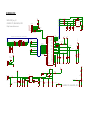
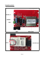
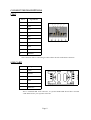
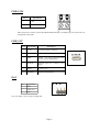
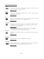
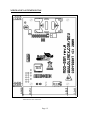
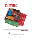
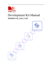
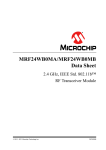
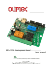
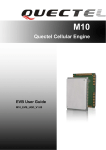
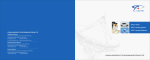
MOD-GSM development board
User's manual
All boards produced by Olimex are ROHS compliant
Rev. E, February 2013
Copyright(c) 2013, OLIMEX Ltd, All rights reserved
Page 1
INTRODUCTION
MOD-GSM is excellent board for adding remote monitoring and control with the
use of the GSM cellular network. With this module you can use all of the the
features of each one of Olimex's boards with on-board UEXT connector by GSM
network. Also the board can work in stand alone mode, but only when the SIM
card is without PIN code. In stand alone mode MOD-GSM don't offer much
opportunities. It can receive information by GSM network, but if you want to
operate with this information, you will need appropriate board with UEXT
connected to MOD-GSM. Choose the other board depending on the application
you want to have. MOD-GSM contains quad-band GSM GPRS module
850/900/1800/1900Mhz inside which covers most used GSM networks around the
world. The GSM antenna is build in the board so no need for external expensive
GSM antennas.
BOARD FEATURES
•
•
•
•
•
•
•
•
•
•
•
GSM/GPRS quad-band MODULE 850/900/1800/1900Mhz with build onboard GSM cellular antenna
Li-ion backup battery 3.7 V 1200 mAh for up to 200 hours of GSM module
stand-by
SIM-card holder
Status LED
On-GSM module temperature sensor
UEXT
PWR_EXT
PWRKEY
On-board DC-DC converter for stand alone mode and battery recharge
PCB: FR-4, 1 mm (0,039"), solder mask, silkscreen component print
Dimensions: 79.2x57.6 mm (3.1182x2.268")
ELECTROSTATIC WARNING
The MOD-GSM board is shipped in protective anti-static packaging. The board
must not be subject to high electrostatic potentials. General practice for working
with static sensitive devices should be applied when working with this board.
BOARD USE REQUIREMENTS
Hardware:
12V, 800mA at least Adapter, if you want to recharge the battery.
Some of Olimex boards with UEXT on it.
Important: If your board does not work, first try to charge the battery as
you power supply the board for few hours. Note that the baud
rate it is set on hardware level to 115200. Consider using
115200 when connected to the terminal or host board.
Page 2
MODULE FEATURES
–
Power Supply – single supply voltage 3.4V – 4.5V
–
Power saving – typical power consumption in SLEEP mode to 2.5mA (BS-PAMFRMS=5)
–
Charging – Supports charging control for Li-Ion battery
–
Frequency bands:
–
SIM340DZ Quad-band: GSM 850, EGSM 900, DCS 1800, PCS 1900. The
SIM340DZ can search the 4 frequency bands automatically. The
frequency bands also can be set by AT command.
–
Compliant to GSM Phase 2/2+
–
GSM class – Small MS
–
Transmit Power
–
–
–
–
–
Class 4 (2W) at EGSM 900
–
Class 1 (1W) at DCS1800 and PCS 1900
GPRS connectivity
–
GPRS multi-slot class 8 (optional)
–
GPRS multi-slot class 10 ( default)
–
GPRS mobile station class B
Temperature range
–
Normal operation: -20°C to +55°C
–
Restricted operation: -30°C to -20°C and +55°C to +80°C
–
Storage temperature -40°C to +80°C
DATA GPRS:
–
GPRS data downlink transfer: max. 85.6 kbps
–
GPRS data uplink transfer: max. 42.8 kbps
–
Coding scheme: CS-1, CS-2, CS-3 and CS-4
–
SIM340DZ supports the protocols PAP (Password Authentication
Protocol) usually used for PPP connections
–
The SIM340DZ integrates the TCP/IP protocol
–
Support Packet Switched Broadcast Control Channel (PBCCH)
–
CSD transmission rates: 2.4, 4.8, 9.6, 14.4 kbps, non-transparent
–
Unstructured Supplementary Services Data (USSD) support
SMS
–
MT, MO, CB, Text and PDU mode
–
SMS storage: SIM card
–
FAX - Group 3 Class 1
–
SIM interface - Support SIM card: 1.8V ,3V
–
External antenna - Connected via 50 Ohm antenna connector or antenna pad
Page 3
–
–
Audio features - Speech codec modes:
–
Half Rate (ETS 06.20)
–
Full Rate (ETS 06.10)
–
Enhanced Full Rate (ETS 06.50/06.60/06.80)
–
Echo suppression
Serial interface and Debug interface
–
Serial Port: Seven lines on Serial Port Interface
–
Serial Port can be used for CSD FAX, GPRS service and sending AT
command of controlling module.
–
Auto bauding supports baud rates from 1200 bps to 115200bps.
–
Debug port: provide two lines on Serial Port Interface /TXD and /RXD
–
Debug port is only used for debugging
–
Phonebook management - Support phonebook types: SM, FD, LD, MC, RC, ON,
ME,BN,VM,LA,DC,SD
–
SIM Application Toolkit - Support SAT class 3, GSM 11.14 Release 99
–
Real time clock – Implemented
–
Timer function - Programmable via AT command
–
Physical characteristics
–
–
Size: 33±0.15 x 33±0.15 x 3±0.3 mm
–
Weight: 7.8g
Firmware upgrade – over serial interface
Page 4
SCHEMATIC
U1
1
3
MAIN_TX
TXD
DBG_TX
BH10R
R27
10K
DRX/MRX
1
3
MAIN_RX
RXD
DBG_RX
VBAT
MAIN_RX
MAIN_TX
DTR
RTS
CTS
RI
DCD
DBG_TX
DBG_RX
3
4
43
44
45
11
42
2
1
ANT
GSM_PCB_ANT
33
BAT_E
90-DEGREE
1
2
BAT
1
2
3
18
19
20
21
23
24
26
25
TEMP_BAT
ANTENNA
GND1
GND2
GND3
GND4
GND5
GND6
GND7
GND8
GND9
MIC2P
MIC2N
MIC1N
MIC1P
EAR+
RERAUDIOOUT+
AUDIOOUT-
AGND
2
VSIM
1
VSIM
SIMDATA
SIMCLK
SIMRST
9
6
7
8
47
+5V
TEMP_BAT
15
28
R14
R15
27
29
C18
C19
C20
330pF(NA)
2.2uF(NA)
220nF(NA)
5V_CHG_E
1
NA
NA
2
1
0
VCC
GND
6
5
4
SIM
SIM-HOLDER
4V
2
AUXADC
R16
NA
PWRKEY
22
C14
47uF/6.3V
C15
C17
100nF
PWRKEY
1000uF/6.3V/8x12/low_ESR
SIM340D
1x3
VBAT
4V_E
1
R5
R4
4.99k/1%
VR1
1
6
1N4004(SMD)
+
PWR
9-12VDC
C2
1000uF/16VDC
GND
C3
2.2uF
R2
C4
R1
68k
4.7k
7
4
VIN
RT
INV
SW
EN/SYNC
GND
FB
BD9778HFP
5
2
L1
15k/1%
C10
10nF(NA)
STAT
red
DCDC_E
R6
1
2
0
4.99k/1%
R9
560R
15uH/DBS135
3
C5
4.7nF
NETLIGHT
R3
150k
D2
1N5822(SMC)
C6
10uF/10V/1206
C7
220uF/10V/tant
+
D1
+
1
2
100nF
TB2_3.5MM
+5V
2
NA
+12V
C21
1nF(NA)
NA
38
39
17
30
31
32
34
35
36
37
48
SIMNC
VBAT
NETLIGHT
41
12
SIMIO
SIMRST
VBAT
TXD
CTS
DCD
PWRKEY
22R
2
1K
NA(1K)
NA(1K)
(NA)1K
R13
SIMCLK
1
R22
R23
R24
R25
2
R17 R26
10K 33K
1K
NA(3.3K)
NA(1K)
NA(1K)
DTX/MTX
SIMRST
+
R18
R19
R20
R21
2
4
6
8
10
2
RXD
RTS
DTR
RI
1
3
5
7
9
3
C16
220uF/10V/tant
UEXT
STATUS
VSIM
GPO1
SIMDATA
SPI_DATA
SIMCLK
SPI_CLK
SIMRESET
SPI_CS
SIM_PRESENCE
SPI_D/C
KBROW0
BACKUP
VCHG
RXD
TXD
TEMP_BAT
DTR
AUXADC
RTS
CTS
NETLIGHT
RI
POWERKEY
DCD
DEBUG_TX
VBAT1
DEBUG_RX
VBAT2
C13
5
40
14
13
46
16
10
TXD,RXD,RTS,CTS,DTR,DCD,RI,DBG_TX,DBG_RX,MAIN_RX,MAIN_TX
22R
OPEN
AUXADC
CON61.27MM-6-SMALL
22R
R12
+
+12V
R11
SIMCLK
+
220
220
R29
R28
VBAT
10uF/10V/1206
1
2
3
4
5
6
10k
R10
SIMDATA
DOW NLOAD
D3
1N5819S
PWR_EXT
5V_IN
GND
VBAT
PWR_IN
GPIO1
AUXADC
VSIM,SIMDATA,SIMCLK,SIMRST
+5V
MOD-GSM_rev_A1
OLIMEX LTD, BULGARIA, 2013
https://www.olimex.com
1000uF/6.3V/8x12/low_ESR
R7
2k
C8
1
2
AGND_E
ON
R8
33k
OLIMEX LTD, BULGARIA, 2013
Q1
BC817
BOARD LAYOUT
Page 6
POWER SUPPLY CIRCUIT
The power supply of MOD-GSM may be done in two ways:
1.
Power from +9 - 12VDC without using the external backup battery.
In this case the external power supply is used for supplying of 4V to GSM
module and thus the module can be powered only from external power
supply and the battery must not be connected.
In this case the jumpers have to be configured as follows:
− jumper BAT_E must be open
− jumper 4V_E must be closed
− jumper 4V must be closed
− jumper 5V_CHG_E must be open.
− DCDC_E must be closed
Power consumption in this mode is:
− near to 70mA when have a conversation.
− around 20mA in normal mode (without conversation).
Important: 4V_E, 4V and 5V_CHG_E jumpers have to be moved together.
2. Power from +12VDC with external 4.2V Li backup battery. The GSM module
is powered always via the battery voltage and the external power supply is
used only for charging the battery if it is discharged, i.e. if you have
plugged external power supply the battery will be charged and if the board
is not powered from external power supply the board will work until the
battery dies.
In this case the jumpers have to be configured as follows:
− jumper BAT_E must be closed
− jumper 4V_E must be open
− jumper 4V must be open
− jumper 5V_CHG_E must be closed
− DCDC_E must be closed
− Power consumption in this mode:
Depends on live of the battery and vary from 260mA to 330mA (fully
discharged battery). If we supply the module only via battery, without
external power supply, the current through the battery is between 15mA
and 30mA if there is no conversation, and between 180mA - 240mA when
there is conversation.
Page 7
CONNECTOR DESCRIPTIONS
JTAG
Pin #
Signal Name
1
NC
2
GND
3
RXD
4
TXD
5
RTS
6
CTS
7
DTR
8
DCD
9
RI
10
PWRKEY
This connector allows connecting to other Olimex boards with UEXT connector.
SIM-CARD
Pin #
Signal Name
1
VSIM
2
SIMRST
3
SIMCLK
4
GND
5
NC
6
SIMDATA
This is standard SIM card connector, to operate MOD-GSM should have inserted
valid SIM card for your operator network.
Page 8
PWR-CON
Pin #
Signal Name
1
+12V
2
GND
This connector is used to power the MOD-GSM. External (+9-12VDC) power source have to
be applied to this pins.
PWR_EXT
Pin #
Signal Name
Description
1
5V_IN
5V input for battery recharge
2
GND
Ground
3
VBAT
Output – for power supplying other
devices from the GSM battery
4
PWR_IN
Optional input for external power
supply
5
GPIO1
Doesn't work
6
AUXADC
Input for analog signal
BAT
Pin #
Signal Name
1
VBAT
2
TEMP_BAT
3
GND
Note: The battery doesn't support TEMP_BAT.
Page 9
JUMPER DESCRIPTION
BAT_E
Connects 3.7V Li-ion battery to the GSM module. Default state is to be open to not
drain the battery during stocking the modules.
Default state - open
4V_E
This jumper is used when power the module without
enable 4V to the DCDC output.
battery.
When connected
Default state – open.
4V
This jumper is used when power the module without battery. When connected the
jumper enable 4V to VBAT power pins of SIM340D module.
Default state – open.
5V_CHG_E
This jumper is used when the battery is present and allows battery charging.
Connects the DCDC converter output (5V or 4V according 4V_E jumper state) to
VCHG power pin of SIM340D module.
Default state closed
Important: 4V_E, 4V and 5V_CHG_E jumpers have to be moved together.
Do not plug in external +12V if BAT_E jumper is open!
DCDC_E
Enable DCDC. Connect DCDC output ((5V or 4V according 4V_E jumper state) to the
module.
Default state closed
Download
When the jumper is closed allow SIM340D firmware upgrade.
Default state is open
DTX/ MTX
The DebugTX/MainTX defines whether Debug TX terminal or Main TX terminal of
SIM340D module is connected to FT232RL virtual com port driver.
Default state is DTX
Page 10
DRX /MRX
The DebugRX/MainRX define whether Debug RX terminal or Main RX terminal of
SIM340D module is connected to FT232RL virtual com port driver.
Default state is DRX
AGND_E
Enable board analog ground.
Default state is closed
INPUT/OUTPUT
PWRKEY button – turns on the MOD-GSM module. You can turn on the SIM340D
by driving the PWRKEY to a low level voltage for period time from 500mS to 1S
Status LED ( red) with name STAT – indicates the state of SIM340D module.
STAT is off state - SIM340D is not running
64ms On/ 800ms Off - SIM340D does not find the network
64ms On/ 3000ms Off - SIM340D find the network
64ms On/ 300ms Off - GPRS communication
IMPORTANT NOTE ABOUT THE UEXT
The information below is for older revisions of the board. If your board doesn't
have the serial resistors mentioned below then there is no need to perform the
actions mentioned below!
If MOD-GSM doesn't transmit properly data on the UEXT of another Olimex board,
it might be because some other boards can interfere with MOD-GSM's signals. If the
host board has any signal on the I2C and/or the SPI on the UEXT there is very high
chance of erroneous behavior.
There are two workarounds:
1. Cut the UEXT cable wires 5,6,7,8,9,10. Only wires 1,2,3,4 (NC, GND, RXD, TXD)
should remain.
OR
2. Remove resistors R19, R20, R21, R23, R24, R25
Page 11
MECHANICAL DIMENSIONS
All measures are in inches.
Page 12
AVAILABLE DEMO SOFTWARE
- Please check the MOD-GSM web pages (standard edition and battery edition):
https://www.olimex.com/Products/Modules/RF/MOD-GSM/
https://www.olimex.com/Products/Modules/RF/MOD-GSM-B/
ORDER CODE
MOD-GSM assembled and tested.
How to order?
You can order directly from our web shop or from any of our distributors.
Check our web site https://www.olimex.com/ for more info. List of distributors:
https://www.olimex.com/Distributors/
Board revision history
Rev. A
Rev. A1
- initial release
- removed resistors R19, R20, R21, R23, R24, R25
Document revision history
Rev. B
Rev. C
Rev. D
Rev. E
- edited October 2011 – changes in POWER SUPPLY CIRCUIT –
more detailed
- added note about the recommended baud rate on page 2
- added important note about UEXT line; various formatting
changes
- updated schematic and disclaimer
Page 13
© 2013 Olimex Ltd. Olimex®, logo and combinations thereof, are registered trademarks of Olimex
Ltd. Other product names may be trademarks of others and the rights belong to their respective
owners.
The information in this document is provided in connection with Olimex products. No license,
express or implied or otherwise, to any intellectual property right is granted by this document or
in connection with the sale of Olimex products.
The hardware schematic is released under the Creative Commons Attribution-Share Alike 3.0 United
States License. You may reproduce it for both your own personal use, and for commer cial use. You
will have to provide a link to the original creator of the project https://www.olimex.com on any
documentation or website.
You may also modify the files, but you must then release them as well under the same terms. Credit
can be attributed through a link to the creator website: https://www.olimex.com
The software is released under GPL.
It is possible that the pictures in this manual differ from the latest revision of the board.
The product described in this document is subject to continuous development and improvements. All
particulars of the product and its use contained in this document are given by OLIMEX in good faith.
However all warranties implied or expressed including but not limited to implied warranties of
merchantability or fitness for purpose are excluded. This document is intended only to assist the reader
in the use of the product. OLIMEX Ltd. shall not be liable for any loss or damage arising from the use
of any information in this document or any error or omission in such information or any incorrect use
of the product.
This evaluation board/kit is intended for use for engineering development, demonstration, or
evaluation purposes only and is not considered by OLIMEX to be a finished end-product fit for
general consumer use. Persons handling the product must have electronics training and observe good
engineering practice standards. As such, the goods being provided are not intended to be complete in
terms of required design-, marketing-, and/or manufacturing-related protective considerations,
including product safety and environmental measures typically found in end products that incorporate
such semiconductor components or circuit boards.
Olimex currently deals with a variety of customers for products, and therefore our arrangement with
the user is not exclusive. Olimex assumes no liability for applications assistance, customer product
design, software performance, or infringement of patents or services described herein.
THERE IS NO WARRANTY FOR THE DESIGN MATERIALS AND THE
COMPONENTS USED TO CREATE MOD-GSM. THEY ARE CONSIDERED
SUITABLE ONLY FOR MOD-GSM.
Page 14