1
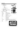
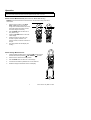
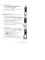
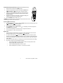
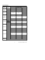
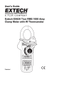
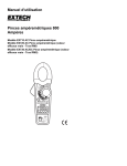
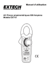
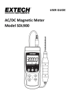
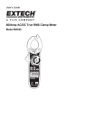
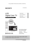
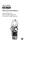
User's Guide 800 Amp Clamp Meters EX710 AC Clamp meter EX720 True RMS AC Clamp meter EX730 AC/DC True RMS Clamp meter Introduction Congratulations on your purchase of the EX710, EX720, or EX730 Clamp DMM. Careful use of this meter will provide many years of reliable service. Safety International Safety Symbols This symbol, adjacent to another symbol or terminal, indicates the user must refer to the manual for further information. This symbol, adjacent to a terminal, indicates that, under normal use, hazardous voltages may be present Double insulation SAFETY NOTES Do not exceed the maximum allowable input range of any function. Do not apply voltage to meter when resistance function is selected. Set the function switch OFF when the meter is not in use. Remove the battery if meter is to be stored for longer than 60 days. WARNINGS Set function switch to the appropriate position before measuring. When measuring volts do not switch to current/resistance modes. Do not measure current on a circuit whose voltage exceeds 600V. When changing ranges always disconnect the test leads from the circuit under test. UL Note A UL mark does not indicate that this product has been evaluated for accuracy. Function Maximum Input A AC, A DC (A DC on Model EX730 only) 800A DC/AC V DC, V AC 600V DC/AC Resistance, Capacitance, Frequency, Diode Test 250V DC/AC Temperature (EX720 & EX730 only) 60V DC, 24V AC 2 EX710-720-730 –EU_ENG V3.0 4/05 CAUTIONS Improper use of this meter can cause damage, shock, injury or death. Read and understand this user manual before operating the meter. Always remove the test leads before replacing the battery or fuses. Inspect the condition of the test leads and the meter itself for any damage before operating the meter. Repair or replace any damage before use. Use great care when making measurements if the voltages are greater than 25VAC rms or 35VDC. These voltages are considered a shock hazard. Always discharge capacitors and remove power from the device under test before performing Diode, Resistance or Continuity tests. Voltage checks on electrical outlets can be difficult and misleading because of the uncertainty of connection to the recessed electrical contacts. Other means should be used to ensure that the terminals are not "live". If the equipment is used in a manner not specified by the manufacturer, the protection provided by the equipment may be impaired. This device is not a toy and must not reach children’s hands. It contains hazardous objects as well as small parts that the children could swallow. In case a child swallows any of them, please contact a physician immediately Do not leave batteries and packing material lying around unattended; they can be dangerous for children if they use them as toys In case the device is going to be unused for an extended period of time, remove the batteries to prevent them from training Expired or damaged batteries can cause cauterization on contact with the skin. Always, therefore, use suitable hand gloves in such cases See that the batteries are not short-circuited. Do not throw batteries into the fire. 3 EX710-720-730 –EU_ENG V3.0 4/05 Description Meter Description (Picture of EX730) 1. Current clamp 2. Clamp opening trigger 3. Control buttons: Data Hold Mode Peak Backlight DCA Zero (EX730 only) 4. 5. Backlit LCD Display COM negative input jack for black test lead 6. Rotary function switch 7. V··CAP·TEMP·Hz· lead positive input jack for red Display icons Description HOLD Data Hold Minus sign Negative reading display 0 to 3999 Measurement display digits DC ZERO DCA Zero (Model EX730 only) PEAK Peak capture AUTO Auto Range mode DC/AC Direct Current / Alternating Current BAT Low battery mV or V Milli-volts or Volts (Voltage) Ohms (Resistance) A Amperes (Current) F Farad (Capacitance) Hz Hertz (Frequency) o F and oC Fahrenheit and Celsius units (Temperature) (Model EX730 only) n, m, , M, k Unit of measure prefixes: nano, milli, micro, mega, and kilo ))) Continuity test Diode test 4 EX710-720-730 –EU_ENG V3.0 4/05 Operation NOTES: Read and understand all Warning and Caution statements in this operation manual prior to using this meter. Set the function select switch to the OFF position when the meter is not in use. AC/DC Current Measurements (DC Current on Model EX730 only) WARNING: Ensure that the test leads are disconnected from the meter before making current clamp measurements. 1. Set the Function switch to the 800A, 400A, or 40A range. If the approx. range of the measurement is not known, select the highest range then move to the lower ranges if necessary. 2. Use the MODE button to select AC or DC. (EX730 only). 3. Press the DC ZERO button to zero the meter display. 4. Press the trigger to open jaw. Fully enclose only one conductor. For optimum results, center the conductor in the jaw. 5. The clamp meter LCD will display the reading. Correct Incorrect AC/DC Voltage Measurements 1. Insert the black test lead into the negative COM terminal and the red test lead into the positive V··CAP·TEMP·Hz· terminal. 2. Set the function switch to the V Hz position. 3. Use the MODE button to select AC or DC Voltage. 4. Connect the test leads in parallel to the circuit under test. 5. Read the voltage measurement on the LCD display. 5 EX710-720-730 –EU_ENG V3.0 4/05 Resistance Measurements 1. Insert the black test lead into the negative COM terminal and the red test lead into the V··CAP·TEMP·Hz· positive terminal. 2. Set the function switch to the position. 3. Touch the test probe tips across the circuit or component under test. 4. Read the resistance on the LCD display. Capacitance Measurements WARNING: To avoid electric shock, discharge the capacitor under test before measuring. 1. Set the function switch to theCAP position. 2. Insert the black test lead banana plug into the negative COM jack and the red test lead banana plug into the V··CAP·TEMP·Hz· positive jack. 3. Touch the test probe tips across the part under test. If “dISC” appears in the display, remove and discharge the component. 4. Read the capacitance value in the display. 5. The display will indicate the proper decimal point and value. Note: For very large values of capacitance measurement it can take several minutes before the final reading stabilizes. Frequency Measurements 1. Insert the black test lead banana plug into the negative COM jack and the red test lead banana plug into the V··CAP·TEMP·Hz· positive jack. 2. Set the function switch to the V Hz Position. 3. Press and hold the MODE button to select the Frequency (Hz) function. “k Hz” will appear in the display. 4. Touch the test probe tips across the part under test. 5. Read the Frequency value on the display. 6. The display will indicate the proper decimal point and value. 7. Press and hold the MODE button again to return to the voltage mode. 6 EX710-720-730 –EU_ENG V3.0 4/05 Temperature Measurements(Model EX720 and EX730 only) 1. Set the function switch to the TEMP position. 2. Insert the Temperature Probe into the negative COM and the V··CAP·TEMP·Hz· positive jacks, observing polarity. 3. Touch the Temperature Probe head to the device under test. Continue to touch the part under test with the probe until the reading stabilizes. 4. Read the temperature on the display. The digital reading will indicate the proper decimal point and value. 5. Use the MODE button to select oF or oC. WARNING: To avoid electric shock, be sure the thermocouple probe has been removed before changing to another measurement function. Continuity Measurements 1. Insert the black test lead into the negative COM terminal and the red test lead into the V··CAP·TEMP·Hz· positive terminal. 2. Set the function switch to the ))) position. 3. Use the MODE button to select continuity “)))”. The display icons will change when the MODE button is pressed. 4. Touch the test probe tips across the circuit or component under test. 5. If the resistance is < 40, a tone will sound. Diode Test 1. Insert the black test lead banana plug into the negative COM jack and the red test lead banana plug into the V·Ω·CAP·TEMP·Hz· positive jack 2. Turn the function switch to position. Use the MODE button to select the diode function if necessary (diode symbol will appear on the LCD when in Diode test mode) 3. Touch the test probe tips to the diode or semiconductor junction under test. Note the meter reading 4. Reverse the test lead polarity by reversing the red and black leads. Note this reading 5. The diode or junction can be evaluated as follows: If one reading displays a value (typically 0.400V to 0.900V) and the other reading displays OL, the diode is good. If both readings display OL the device is open. If both readings are very small or ‘0’, the device is shorted. 7 EX710-720-730 –EU_ENG V3.0 4/05 Data Hold To freeze the LCD reading, press the HOLD button. While data hold is active, the HOLD icon appears on the LCD. Press the HOLD button again to return to normal operation. DC ZERO (Relative) (EX730 only) The DC ZERO is a relative feature and can be used in any function. 1. Press the DC ZERO button to zero the display. “ZERO” will appear in the display. The displayed reading is now the actual value less the stored “zero” value. 2. Press the DC ZERO button to view the stored value. “ZERO” will flash in the display. 3. To exit this mode, press and Hold the ZERO button until “ZERO” is no longer in the display. Peak Hold The Peak Hold function captures the peak AC or DC voltage or current. The meter can capture negative or positive peaks as fast as 1 millisecond in duration. 1. Turn the function switch to the A or V position. 2. Use the MODE button to select AC or DC (ADC EX730 only). 3. Allow time for the display to stabilize. 4. Press and Hold the PEAK button until “CAL” appears in the display. This procedure will zero the range selected. 5. Press the PEAK button, Pmax will display. 6. The display will update each time a higher positive peak occurs. 7. Press the PEAK button again, Pmin will display. The display will now update and indicate the lowest negative peak. 8. To return to normal operation, press and hold the PEAK button until the Pmin or Pmax indicator switches off. Note: If the Function switch position is changed after a calibration the Peak Hold calibration must be repeated for the new function selected. LCD Backlight Button The LCD is equipped with backlighting. Press the backlight button to turn the backlight on. Press again to turn the backlight off. Automatic Power OFF In order to conserve battery life, the meter will automatically turn off after approximately 25 minutes. To turn the meter on again, turn the function switch to the OFF position and then to the desired function position. 8 EX710-720-730 –EU_ENG V3.0 4/05 Specifications Function Range & Resolution AC Current 40.00A AC 50/60 Hz Accuracy (% of reading + digits) EX720 EX710 EX730 ± (2.8% + 10d) ± (2.5% + 10d) ± (2.5% + 10d) 400.0A AC ± (2.8% + 8d) ± (2.5% + 8d) ± (2.5% + 8d) True RMS on EX720 & EX730 800A AC ± (3.0% + 8d) ± (2.8% + 5d) ± (2.8% + 5d) DC Current 40.00A DC EX730 only 400.0A DC NA NA ± (2.5% + 5d) ± (2.5% + 7d) 800A DC 400.0mV AC AC Voltage 50/60Hz True RMS on EX720 & EX730 ± (2.8% + 5d) ± (1.5% + 10d) ± (1.0% + 10d) ± (1.0% + 10d) ± (1.8% + 8d) ± (1.5% + 5d) ± (1.5% + 5d) 600V AC ± (2.5% + 8d) ± (2.0% + 5d) ± (2.0% + 5d) 400.0mV DC ± (0.8% + 2d) ± (0.8% + 2d) ± (0.8% + 2d) ± (1.5% + 2d) ± (1.5% + 2d) ± (1.5% + 2d) 600V DC ± (2.0% + 2d) ± (2.0% + 2d) ± (2.0% + 2d) 400.0 ± (1.0% + 4d) ± (1.0% + 4d) ± (1.0% + 4d) ± (1.5% + 2d) ± (1.5% + 2d) ± (1.5% + 2d) ± (2.5% + 3d) ± (2.5% + 3d) ± (2.5% + 3d) 4.000V AC 40.00V AC 400.0V AC 4.000V DC DC Voltage 40.00V DC 400.0V DC 4.000k Resistance 40.00k 400.0k 4.000M 40.00M ± (3.5% + 5d) ± (3.5% + 5d) ± (3.5% + 5d) 4.000nF ± (5.0% + 30d) ± (5.0% + 30d) ± (5.0% + 30d) 40.00nF ± (5.0% + 20d) ± (5.0% + 20d) ± (5.0% + 20d) ± (3.0% + 5d) ± (3.0% + 5d) ± (3.0% + 5d) 400.0µF ± (4.0% + 10d) ± (4.0% + 10d) ± (4.0% + 10d) 4.000mF ± (10% + 10d) ± (10% + 10d) ± (10% + 10d) 400.0nF Capacitance Frequency 4.000µF 40.00µF 40.00mF unspecified unspecified unspecified 4.000kHz ± (1.5% + 2d) ± (1.5% + 2d) ± (1.5% + 2d) Sensitivity: 100V (<50Hz); 50V (50 to 400Hz); 5V (401 to 4000Hz) 9 EX710-720-730 –EU_ENG V3.0 4/05 Function Accuracy Range and Resolution (% of reading + digits) EX710 o Temperature -4 to 1400 F -20 to 760 C EX730 o NA o EX720 ± (3%rdg + 9 F) o NA ± (3%rdg + 5 C) o ± (3%rdg + 9 F) o ± (3%rdg + 5 C) General Specifications Clamp jaw opening 1.2" (30mm) approx. Display 3-3/4 digits (4000 counts) backlit LCD Continuity check Threshold 40; Test current < 0.5mA Diode test Test current of 0.3mA typical; Open circuit voltage < 3VDC typical Low Battery indication ‘BAT’ is displayed Over-range indication ‘OL’ display Measurement rate 2 readings per second, nominal PEAK Captures peaks >1ms Temperature sensor Type K thermocouple Input Impedance 10M (VDC and VAC) AC bandwidth 50 to 400Hz (AAC and VAC) AC response True rms (AAC and VAC) on EX720 & EX730 Crest Factor 3.0 in 40A and 400A ranges, 1.4 in 800A range (50/60Hz and 5% to 100% of range) Operating Temperature 41oF to 104oF (5oC to 40oC) Storage Temperature -4oF to 140oF (-20oC to 60oC) Operating Humidity Max 80% up to 87oF (31oC) decreasing linearly to 50% at 104oF(40oC) Storage Humidity <80% Operating Altitude 7000ft. (2000meters) maximum. Battery One (1) 9V Battery Auto power OFF After approx. 25 minutes Dimensions & Weight Safety 9.0 x 3.1 x 2.0" (229 x 80 x 49mm); 10.7 oz. (303g) For indoor use and in accordance with the requirements for double insulation to IEC1010-1 (2001): EN61010-1 (2001) Overvoltage Category III 600V and Category II 1000V, Pollution Degree 2. 10 EX710-720-730 –EU_ENG V3.0 4/05 Maintenance WARNING: To avoid electrical shock, disconnect the meter from any circuit, remove the test leads from the input terminals, and turn OFF the meter before opening the case. Do not operate the meter with an open case. Cleaning and Storage Periodically wipe the case with a damp cloth and mild detergent; do not use abrasives or solvents. If the meter is not to be used for 60 days or more, remove the battery and store it separately. Battery Replacement 1. Remove the Phillips head screw that secures the rear battery door 2. Open the battery compartment 3. Replace the 9V battery 4. Secure the battery compartment You, as the end user, are legally bound (Battery ordinance) to return all used batteries and accumulators; disposal in the household garbage is prohibited! You can hand over your used batteries / accumulators, gratuitously, at the collection points for our branches in your community or wherever batteries / accumulators are sold! Disposal Follow the valid legal stipulations in respect of the disposal of the device at the end of its lifecycle Copyright © 2005 Extech Instruments Corporation All rights reserved including the right of reproduction in whole or in part in any form. www.extech.com 11 EX710-720-730 –EU_ENG V3.0 4/05