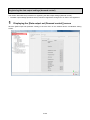
1
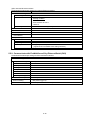
Mitsubishi Energy Saving Data Collecting Server
EcoWebServerIII
Model name
MES3-255C-EN/MES3-255C-DM-EN
Instruction Manual – Setting
● Be sure to read this manual before using the equipment.
Please deliver this manual to the end user.
Table of Contents
1. Preface ................................................................................................................................................... 1-1
1.1. General notes ...................................................................................................................................... 1-1
1.1.1. Warranty ......................................................................................................................................... 1-1
1.1.2. Trademarks .................................................................................................................................... 1-1
1.2. Safety precautions ............................................................................................................................... 1-2
1.2.1. Storage ........................................................................................................................................... 1-2
1.2.2. Other notes ..................................................................................................................................... 1-2
1.3. Precautions for use ............................................................................................................................. 1-2
1.4. Main features and specifications ......................................................................................................... 1-4
1.4.1. Main features of the EcoWebServerIII setting software ................................................................. 1-4
1.4.2. System configuration ...................................................................................................................... 1-4
1.4.3. Specifications ................................................................................................................................. 1-5
2. Before use ............................................................................................................................................. 2-1
2.1. Recommended system environment ................................................................................................... 2-1
2.2. Glossary .............................................................................................................................................. 2-2
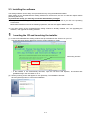
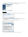
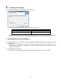
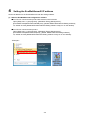
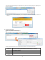
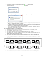
2.3. Installing the software .......................................................................................................................... 2-4
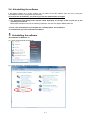
2.4. Uninstalling the software ..................................................................................................................... 2-7
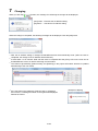
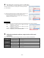
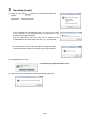
2.5. Upgrading the software ....................................................................................................................... 2-9
3. Flow of settings .................................................................................................................................... 3-1
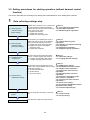
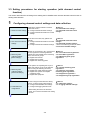
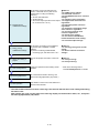
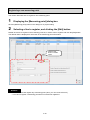
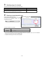
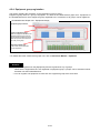
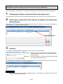
3.1. Procedures for initial settings (Common) ............................................................................................ 3-1
3.2. Setting procedures for starting operation (without demand control function) ..................................... 3-8
3.3. Setting procedures for starting operation (with demand control function)........................................... 3-9
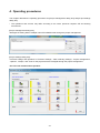
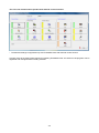
4. Operating procedures .......................................................................................................................... 4-1
4.1. Starting/exiting the setting software ..................................................................................................... 4-3
4.2. Project management ........................................................................................................................... 4-5
4.2.1. Registering a new project ............................................................................................................... 4-5
4.2.2. Opening a project ........................................................................................................................... 4-7
4.2.3. Deleting a project ........................................................................................................................... 4-8
4.2.4. Modifying the project information ................................................................................................... 4-9
4.2.5. Copying a project ......................................................................................................................... 4-10
4.2.6. Backing up projects ....................................................................................................................... 4-11
4.2.7. Restoring projects ........................................................................................................................ 4-14
4.3. Demand control and Control Section Specifications (only with demand control function) ................ 4-17
4.3.1. Demand measuring function ........................................................................................................ 4-17
4.3.2. Demand control and alarm function ............................................................................................. 4-27
4.3.3. Demand Control Function ............................................................................................................ 4-35
4.3.4. Seasonal Time Zone Control Function ......................................................................................... 4-55
Configure the demand control setting ......................................................................................................... 4-56
4.3.5. Normal demand setting (setting of the instrument information) ................................................... 4-56
4.3.6. Demand alarm and control setting ............................................................................................... 4-61
4.3.7. Demand calendar setting(Only when carrying out management based on calendar setting) 4-68
4.4. Measuring Data Collection Settings [Normal Settings] ..................................................................... 4-76
4.4.1. CC-Link terminal registration ........................................................................................................ 4-76
4.4.2. PLC/GOT registration ................................................................................................................... 4-85
4.4.3. Measuring point registration ......................................................................................................... 4-92
4.4.4. Measuring point group registration ............................................................................................. 4-107
4.5. Measuring data collection setting [Advanced settings] .................................................................... 4-112
4.5.1. Virtual measuring point registration ............................................................................................. 4-112
4.5.2. Specific consumption measuring point registration .................................................................... 4-121
4.5.3. Equipment registration ............................................................................................................... 4-129
i
4.5.4. Equipment group registration ..................................................................................................... 4-137
4.6. Project operation ............................................................................................................................. 4-144
4.6.1. Project saving ............................................................................................................................. 4-144
4.6.2. Project writing ............................................................................................................................. 4-145
4.6.3. Project reading ........................................................................................................................... 4-150
4.6.4. Collation of project...................................................................................................................... 4-153
4.7. Options ............................................................................................................................................ 4-157
4.7.1. IP address settings ..................................................................................................................... 4-158
4.7.2. Setting of the time ...................................................................................................................... 4-170
4.7.3. Auto time settings ....................................................................................................................... 4-174
4.7.4. Logging date/time settings ......................................................................................................... 4-176
4.7.5. Setting of the login IDs and passwords ...................................................................................... 4-178
4.8. Setting external device coordination ............................................................................................... 4-187
4.8.1. Data output settings ................................................................................................................... 4-188
4.8.2. Data output settings (demand control) (Only when demand control function is provided) ........ 4-198
4.8.3. Contact output settings............................................................................................................... 4-203
4.8.4. SMTP server settings ................................................................................................................. 4-213
4.8.5. Demand notification (Only with models provided with demand control function)....................... 4-217
4.8.6. EcoWebServerIII error notification settings ................................................................................ 4-221
4.8.7. Regular report registration ......................................................................................................... 4-229
4.8.8. Upper and lower limit monitoring notification registration .......................................................... 4-235
4.8.9. Operating status monitoring notification registration .................................................................. 4-242
4.8.10. Specific consumption target value monitoring notification registration ...................................... 4-249
4.8.11. Energy planning value monitoring notification registration......................................................... 4-256
4.8.12. FTP server setting ...................................................................................................................... 4-263
4.8.13. Transfer enable/disable, transfer destination folder setting ....................................................... 4-267
4.8.14. Energy saving level monitor setting (Only for models with demand control function) ............... 4-270
4.8.15. Air-conditioner connection settings (Only for models with demand control function) ................ 4-273
4.9. Test and Adjustment Function ......................................................................................................... 4-276
4.9.1. Terminal connection check ......................................................................................................... 4-277
4.9.2. Contact output operation check ................................................................................................. 4-281
4.9.3. Demand notification (only models with demand control function) .............................................. 4-286
4.9.4. Error, regular notification check .................................................................................................. 4-290
4.9.5. Measuring point data monitoring report check ........................................................................... 4-294
4.9.6. File automatic transfer check ..................................................................................................... 4-298
4.9.7. Air-controller connection check (only models with demand control function) ............................ 4-302
4.9.8. Integrated count value settings (only models with demand control function) ............................ 4-304
4.9.9. Data collection ............................................................................................................................ 4-308
4.9.10. Deleting data ............................................................................................................................... 4-311
4.9.11. EcoWebServerIII reset ............................................................................................................... 4-314
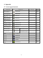
5. Appendix ............................................................................................................................................... 5-1
5.1. List of support terminals ...................................................................................................................... 5-1
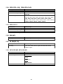
5.2. List of model information ..................................................................................................................... 5-3
5.2.1. EMU4-BD1-MB ............................................................................................................................... 5-3
5.2.2. EMU4-HD1-MB .............................................................................................................................. 5-3
5.2.3. EMU2-RD3-C,EMU2-RD5-C,EMU2-RD7-C ............................................................................. 5-3
5.2.4. EMU2-RD2-C-4W,EMU2-RD4-C-4W .......................................................................................... 5-4
5.2.5. EMU3-DP1-C ................................................................................................................................. 5-4
5.2.6. MDU(WS) ....................................................................................................................................... 5-4
5.2.7. AE-SW(BIF-CC) ............................................................................................................................. 5-4
5.2.8. ME96SSR-MB, ME96SSH-MB ...................................................................................................... 5-4
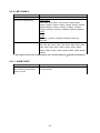
5.2.9. ME110SSR-C(H) ............................................................................................................................ 5-5
5.2.10. ME110NSR-C ................................................................................................................................. 5-6
ii
5.2.11. AJ65BT-68TD ................................................................................................................................. 5-6
5.3. List of measured items ........................................................................................................................ 5-7
5.3.1. EMU4-BD1-MB ............................................................................................................................... 5-7
5.3.2. EMU4-HD1-MB .............................................................................................................................. 5-8
5.3.3. EMU2-RD3-C, EMU2-RD5-C, EMU2-RD7-B ................................................................................. 5-9
5.3.4. EMU2-RD2-C-4W, EMU2-RD4-C-4W .......................................................................................... 5-10
5.3.5. EMU3-DP1-C ............................................................................................................................... 5-12
5.3.6. MDU(WS-V)............................................................................................................................. 5-13
5.3.7. MDU(WS) ..................................................................................................................................... 5-14
5.3.8. AE-SW(BIF-CC) ........................................................................................................................... 5-15
5.3.9. ME96SSR-MB (1P2W, 3P3W) ..................................................................................................... 5-16
5.3.10. ME96SSR-MB (1P3W) ................................................................................................................. 5-17
5.3.11. ME96SSR-MB (3P4W) ................................................................................................................. 5-18
5.3.12. ME96SSH-MB (1P2W, 3P3W) ..................................................................................................... 5-20
5.3.13. ME96SSH-MB (1P3W) ................................................................................................................. 5-22
5.3.14. ME96SSH-MB (3P4W) ................................................................................................................. 5-24
5.3.15. ME96NSR .................................................................................................................................... 5-27
5.3.16. ME110SSR-C(H) (1P2W, 1P3W, 3P3W) ..................................................................................... 5-30
5.3.17. ME110SSR-C(H) (3P4W) ............................................................................................................. 5-31
5.3.18. ME110NSR-C ............................................................................................................................... 5-33
5.3.19. AJ65BT-68TD ............................................................................................................................... 5-34
5.3.20. AJ65BT-64RD3 ............................................................................................................................ 5-34
5.3.21. AJ65BT-64AD ............................................................................................................................... 5-35
5.3.22. AJ65SBTB1-8D ............................................................................................................................ 5-35
5.3.23. AJ65SBTB1-16D .......................................................................................................................... 5-35
5.3.24. AJ65SBTB1-32D .......................................................................................................................... 5-36
5.3.25. AJ65SBTB1-16DT ........................................................................................................................ 5-36
5.3.26. AJ65SBTB1-32DT ........................................................................................................................ 5-36
5.4. List of measured items of devices ..................................................................................................... 5-37
5.4.1. Bit data ......................................................................................................................................... 5-37
5.4.2. Word data ..................................................................................................................................... 5-40
5.4.3. Long data ..................................................................................................................................... 5-42
5.5. PLC Setting ....................................................................................................................................... 5-44
5.5.1. Communicate with EcoWebServerIII by Ethernet (CH2) ............................................................. 5-44
5.5.2. Communicate with EcoWebServerIII by Ethernet/Serial (CH2) ................................................... 5-45
5.6. GOT communication settings ............................................................................................................ 5-46
5.6.1. Settings to connect EcoWebServerIII to GOT with Ethernet ....................................................... 5-46
5.7. Data output to PLC/GOT ................................................................................................................... 5-48
5.7.1. Double word ................................................................................................................................. 5-48
5.8. Data output specification to PLC/GOT .............................................................................................. 5-49
5.8.1. Data output ................................................................................................................................... 5-49
5.8.2. Measuring error information ......................................................................................................... 5-50
5.8.3. Updating time information ............................................................................................................ 5-50
5.8.4. Outputting demand information (Only with demand control function) .......................................... 5-51
5.9. EcoWebServerIII MC protocol server ................................................................................................ 5-53
5.9.1. Communications parameter ......................................................................................................... 5-53
5.9.2. Local virtual device data output contents (Only with demand control function) ........................... 5-54
5.10. List of FTP commands....................................................................................................................... 5-56
5.10.1. List of FTP commands ................................................................................................................. 5-56
5.10.2. Acquisition of data files by FTP command ................................................................................... 5-57
5.11. List of prohibited characters .............................................................................................................. 5-61
5.12. List of error codes .............................................................................................................................. 5-62
5.12.1. Terminal connection check ........................................................................................................... 5-62
5.12.2. Mail sending check ....................................................................................................................... 5-62
iii
5.12.3. File automatic transfer check ....................................................................................................... 5-62
5.12.4. Air-controller connection check .................................................................................................... 5-62
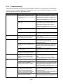
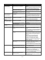
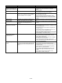
5.13. Troubleshooting ................................................................................................................................. 5-63
iv
1. Preface
Thank you for purchasing Mitsubishi’s Energy Saving Data Collecting Server (hereinafter, EcoWebServerIII).
This instruction manual describes how to manage, set up, and operate projects to operate EcoWebServerIII
and how to operate the EcoWebServerIII setting software (hereinafter, "setting software") for the maintenance
of EcoWebServerIII. This instruction manual assumes that the reader has knowledge of personal computers,
networks, and various types of servers and basic knowledge of electric equipment. Please read it carefully,
and use the product properly.
Keep this instruction manual in an accessible place for future reference whenever needed.
Make sure it is delivered to the end user.
For more information on the display function of EcoWebServerIII, see “Instruction Manual – Operating”.
For information on how to handle the main unit of EcoWebServerIII, see "Instruction Manual – Hardware".
1.1. General notes
1.1.1. Warranty
Please contact your nearest Mitsubishi Sales Office or dealer for technical inquiries regarding the product.
This instruction manual and equipment have undergone strict quality control and product inspections prior
to shipment. However, if any problems occur as a result of the manufacturing of this equipment or
instruction manual, a replacement will be provided. Please contact your dealer in this case. Note that this
does not apply to faults or damage resulting from force majeure or improper usage, etc.
Mitsubishi shall not be held liable for any trouble in the user or third party's system, legal problems, faults
resulting from improper use of equipment, faults occurring during the use of this equipment, or any damage
caused by other faults.
The charge-free warranty period for the product shall be the shorter period either of one year from the date
of your purchase or the date when the product is delivered to your specified delivery location or 18 months
from the time of the shipment from our factories (counted from the date of manufacture).
However, the charge-free warranty shall not apply to the following cases even during the charge-free
warranty period:
(1) When the cause is an improper usage
(2) When the cause is an improper operation
The charge-free warranty becomes invalid at the expiration of the charge-free warranty period.
The charge-free warranty term for repaired parts shall not be extended.
1.1.2. Trademarks
®
®
®
®
®
®
®
Microsoft , Windows , Windows XP, Windows Vista , Windows 7, Windows 8, and Internet Explorer are
registered trademarks or trademarks and products of Microsoft Corporation in the United States and/or
other countries.
Java,
all Java-based trademarks and logos are registered trademarks of Oracle Corporation and its
affiliated companies in the United States and/or other countries.
CompactFlash
TM
is trademarks of SanDisk Corporation.
Ethernet is a registered trademark of Fuji Xerox Co., Ltd.
EcoWebServer is a registered trademark of Mitsubishi Electric Corporation.
Other company names and product names in the manual are registered trademarks or trademarks of their
respective owners.
1-1
1.2. Safety precautions
1.2.1. Storage
When storing the CD-ROM, avoid the following places.
Failure to follow the instruction may cause a read error.
Ambient temperature exceeds the specified temperature range (+5C to +45C).
Relative humidity exceeds 30 to 80% RH or condensation is observed.
Altitude exceeds 1000 m.
Dust, corrosive gas, saline, and oil smoke exist.
Frequent vibration or impact exists.
Exposed to rain fall, water drop, or direct sunlight or near heaters.
Metal pieces or conductive materials blow.
Under strong electromagnetic field or noise.
1.2.2. Other notes
See the instruction manual of EcoWebServerIIIHardware.
1.3. Precautions for use
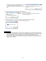
Before configuring data, particular attention must be paid to the following points:
Use the setting software after closing any other applications that are running.
If running in parallel with other applications, the setting software may not operate properly.
If you have any questions about the installation, setting, and other technical matters of browsers and
JavaVM (Java Virtual Machine) on PCs, contact your network administrator (or appropriate divisions).
If you have any questions about the installation, setting, and other technical matters of various servers,
including the SMTP (mail-sending) server and FTP (file) server, contact your network administrator (or
appropriate divisions) or the manufacturer.
We don’t offer technical support for the above.
When having changed the display setting of the measuring point names and other settings, be sure to close
the currently displayed Web browser and restart it. Otherwise, the change might not be updated due to the
cache function of the web browser.
If there is an error in the model information on the terminal registration dialog box, the number of digits after
decimal point of the measured data may be incorrect, or a measurement error may occur.
Be sure to specify
the correct model information.
The monitoring of the upper and lower limits is performed every 10 seconds; therefore, some abnormalities
in the upper and lower limits may not be detected.
Do not use the unit for the monitoring of the measured data of urgency.
Otherwise, an accident may occur. In such cases, we are not responsible for any accidents.
The monitoring of the operation statuses is performed every 10 seconds; therefore, some statuses may not
be detected.
Do not use the unit for the monitoring of alarms of urgency.
Otherwise, an accident may occur. In such cases, we are not responsible for any accidents.
The monitoring of the target Specific consumptions is performed every 1 hour; therefore, the detection may
be delayed.
Do not use the unit for the monitoring of the Specific consumption
data of urgency.
Otherwise, an accident may occur. In such cases, we are not responsible for any accidents.
The monitoring of the energy planned values is performed every 1 day; therefore, the detection may be
delayed.
Do not use the unit for the monitoring of the measured data of urgency.
1-2
Otherwise, an accident may occur. In such cases, we are not responsible for any accidents.
As for the mail delivering through the monitoring notification function, the mail reception may be delayed
according to environments of your SMTP server, network, and mail client.
Do not use the unit for the notifications of urgency.
Otherwise, an accident may occur. In such cases, we are not responsible for any accidents.
The contact output of the monitoring statuses is performed every 10 seconds; therefore, the output may be
delayed from the satisfaction of the contact output condition.
Do not use the unit for the contact output of the monitoring of urgency.
Otherwise, an accident may occur. In such cases, we are not responsible for any accidents
Do
not perform the writing of projects concurrently from multiple client
PCs via a LAN.
Otherwise, the writing may not be performed properly, and EcoWebServerIII may not be launched.
If the demand is not set correctly, a correct measurement may not be possible, the load may be
inadvertently cut off, and it may not be able to cut off the load.
Set the demand correctly.
When an air-conditioning system, etc., is set as the demand control load, if the circuit is configured to
directly cut off the outdoor unit's main power or the compressor’s main power, a system fault could occur,
or the product quality or life may be lost depending on the model.
Consult with the air-conditioner maker for details on compatibility of this product with the air-conditioning
system in use.
1-3
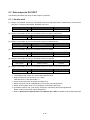
1.4. Main features and specifications
1.4.1. Main features of the EcoWebServerIII setting software
The setting software can manage the EcoWebServerIII projects of up to 50 units from a PC connected to a
LAN.
The setting software can easily configure and modify projects.
The setting software can perform various maintenance functions, including moving the data files stored in
EcoWebServerIII to a PC.
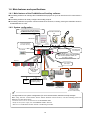
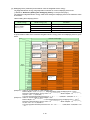
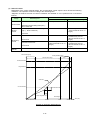
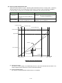
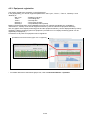
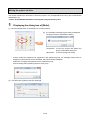
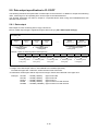
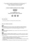
1.4.2. System configuration
View the graph (Internet Explorer)
EcoWebServerIII setting software
Transfer collected
file
Client PC
FTP Server
(File server)
CC-Link terminals
PLC data collecting
SMTP Server
(Mail server)
SNTP Server
(Time server)
Ethernet
EcoWebServerIII (This Product)
Report by Email
Air controller
空調
コントローラ
EcoWebServerIII
Time adjustment
Output the alarm status, data upper/lower
limit over and operation status, etc.,
to a lamp or buzzer
Ethernet
Input a demand
pulse signal
PLC
PLC
PLC
CC-Link
Write collected
data to PLC
device
EcoMonitorPro
MC プロトコル
GOT
MC protocol
client
クライアント
(PATLITE
network
( パトライト
製
ネットワーク監視表示灯
monitoring
lamp))
EMU3
EMU3
シリーズ
Series
Electronic
電子式マルチ
指示計器
multimeasuring
instrument
MDU
MDU
ブレーカ
braker
Contact
input
接点入力
Analog
input
アナログ入力
温度入力input
Temperature
MELSEC-Q energy
MELSEC
-Q 電力計測ユニット
measuring
module
(via
CC-Link
local station))
(CC-Link
ローカル局経由
The figure above is a system configuration (CC-Link communication, demand control) example
When using CC-Link communication device without demand control function, note the following points are
different from the above figure.
・Demand control unit is not attached to the EcoWebServerIII.
・Shape of the power supply unit of EcoWebServerIII is different
・There is no coordination function with air conditioning controller.
1-4
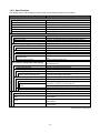
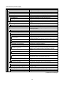
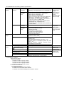
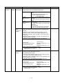
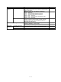
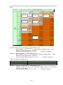
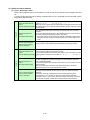
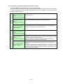
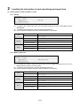
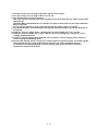
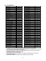
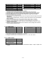
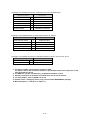
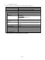
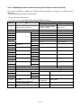
1.4.3. Specifications
The display names and description of the functions of the setting software are as follows:
Name
Description of functions
Project management
New registration of project
Deletion of project
Change of project
Copy of project
Backup of project
Restoration of project
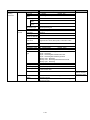
Project settings
Demand settings
Normal
Alarm and control
Calendar
Data collecting settings [Normal settings]
Terminals
Terminal
PLC / GOT
Log in PLC, GOT
Measuring point
Measuring point
Measuring point group set
Data collecting settings [Extended settings]
Virtual
Virtual measuring point
Specific consumption
Specific consumption measuring point
Selection of the measuring point
Equipment
Equipment list
Equipment
Registration of display measuring
point
Equipment group list
Resistration of equipment group
Project management
Save
Write
Read
Collate
Creates a new project.
Deletes a project.
Modifies the content of a project.
Copies a project.
Backs up project information on an external memory.
Restores project information from an external memory.
Configures settings for demand control.
Configures basic settings for demand control.
Configures the demand alarm and demand control settings.
Configures the demand control schedule.
Configures the settings for collecting measuring data.
Displays a list of registered CC-Link terminals.
Registers the CC-Link terminal.
Displays a list of PLCs connected to the registered Ethernet.
Registers the PLC/GOT connected to Ethernet with CH2.
Displays a list of CC-Link measuring points.
Registers the CC-Link terminal or device data as a measuring
point.
Sets the measuring point group.
Configures the settings for the measuring data collection
advanced functions.
Displays a list of virtual measuring points.
Registers the virtual measuring points.
Displays a list of specific consumption measuring points.
Registers the specific consumption measuring point.
Selects the measuring point/virtual measuring point to be used in
the specific consumption computation.
Displays a list of equipment.
Registers a piece of equipment.
Selects a measuring point/virtual measuring point to be used in the
computation of equipment overall efficiency.
Registers a display measuring point of the equipment.
Displays the list of equipment groups.
Registers a piece of equipment in an equipment group.
Saves, writes, reads, and checks a project.
Saves the settings of a project.
Writes the settings of a project onto EcoWebServerIII or a
CompactFlash.
Reads the settings of a project from EcoWebServerIII or a
CompactFlash.
Check the settings of a project against EcoWebServerIII or a
CompactFlash.
(Continued on next page)
1-5
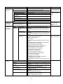
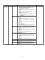
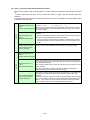
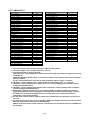
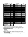
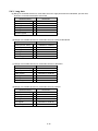
(Continued from previous page)
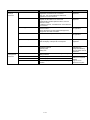
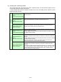
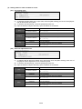
Name
Options
IP address
Time
Auto time adjustment
Set logging time
Password
For maintenance
For getting data
For system management
Output
Output settings
Registration of the data output group
Data output set(Demand control)
Contact output
Registration of contact output condition
Mail notification settings
Set SMTP server
Demand notification
Error notification
Initial condition 1
Initial condition 2
Initial condition 3
Regular report
Registration of regular report
Upper and lower limit monitoring
Upper and lower limit monitoring
notification registration
Operation status monitoring
Registration of operating status
monitoring notification
Specific consumption target value
monitoring
Registration of specific consumption
target value monitoring notification
Energy planning value monitoring
Registration of energy planning value
monitoring notification
File transfer
Set FTP server
Transmission destination folder set
Energy saving cooperation settings
Energy saving level monitor setting
Air-conditioner connection setting
Description of functions
Configures the settings of the unit.
Configures the settings of the IP address and the DNS server.
Reads the time data, and configures the time setting.
Configures the automatic time setting using the SNTP server.
Sets the measuring point data logging date and time.
Changes the login ID and password.
Changes the maintenance loginID and password.
Changes the data acquisition login ID and password.
Changes the system administration login ID and password.
Configures the settings related to collaboration with external
devices.
Displays the list of output groups.
Registers the output groups.
Sets the demand control function's data output destination.
Displays a list of contact output settings, and sets the number of
contact output points.
Registers the contact output conditions.
Configures the mail notification settings.
Configures the mail notification SMTP server.
Configures the demand control and notification settings.
Configures the unit error notification.
Configures the setting of notifications of launch, memory card errors
and measurement error.
Configures the setting of notifications of launch transfer errors, auto
time setting errors, and battery errors.
Configures the setting of notifications of launch data output errors.
Displays the list of regular report settings.
Registers the regular report settings.
Displays the list of upper/lower limit monitoring and notification
Registers an upper and lower limit monitoring and notification.
Displays a list of operating status monitoring and notification
settings.
Registers the operating status monitoring notifications.
Displays a list of specific consumption target value monitoring and
notification settings.
Registers the specific consumption target value.
Displays a list of energy plan value monitoring and notification
settings.
Registers the energy plan value monitoring settings.
Configures the settings for file transfer.
Configures the FTP server for file transfer.
Configures the transfer enable/disable state and transfer
destination folder.
Configures the settings for energy saving collaboration.
Configures the energy saving monitoring and energy saving alarm.
Configures the connection with the air-conditioner controller.
(Continued on next page)
1-6
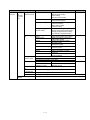
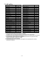
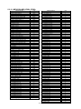
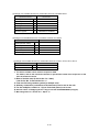
(Continued from previous page)
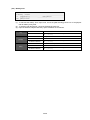
Name
Test
Confirm terminal connection
Confirm contact output
Confirm mail sending
Demand notification
Error, regular notification
Measuring point data monitoring report
Confirm file transfer
Confirm air-conditioner connection
Integration value set
Collect data
Delete data
Reset
Description of functions
Configures the settings for each test and adjustment.
Configures the test for checking connection with the CC-Link
terminal.
Performs a test on all contact outputs.
Performs a test related to mail transmission
Performs a demand control and notification mail send test.
Performs a unit error and regular notification mail send test.
Preforms a measuring point data monitoring report mail send test.
Performs a file transfer function test.
Performs an air-controller connection test.
Sets the demand count value.
Collects the logging data.
Deletes the logging data.
Resets the unit.
1-7
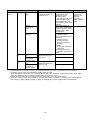
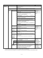
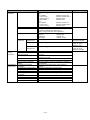
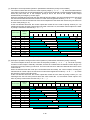
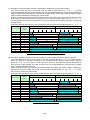
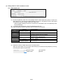
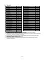
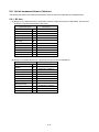
<EcoWebServerIII and setting software specification>
Connection
device
Item
CC-Link
terminal
Number of
connection
Model
name/type
name
PLC/GOT
Measuring
target
Number of
connection
Model
name/type
name
CC-Link terminal
Demand control
Measuring
points
PLC/GOT
All measuring points
measuring points of
operation monitoring
Virtual measuring point
Specific consumption
measuring point
Equipment
Demand measuring point
Specification
Up to 42
Depending on the specification of CC-Link master unit
*1
EMU4-BD1-MB, EMU4-HD1-MB, EMU2-HM1-C,
EMU2-RD1-C, EMU2-RD3-C, EMU2-RD5-C,
EMU2-RD7-C, EMU2-RD2-C-4W,
EMU2-RD4-C-4W, EMU3-DP1-C,
EMU-C7P4-6-A(S), EMU-C7P4-6-A(P), MDU(WS),
MDU(WS-V), AE-SW(BIF-CC), ME110SSR-C,
ME110SSFL-C2H, ME110NSR-C, ME110NSFL-C,
LG-5F-C, LG-10F-C, AJ65BT-68TD,
AJ65BT-64RD3, AJ65BT-64AD, AJ65SBTB1-8D,
AJ65SBTB1-16D, AJ65SBTB1-32D,
AJ65SBTB1-16DT, AJ65SBTB1-32DT, QJ61BT11N,
LCPU/LJ61BT11
32
MELSEC PLC
QCPU/LCPU/QnACPU, ACPU,
AnACPU/AnUCPU,
FXCPU(FX1x), FXCPU(FX3x)
* FXCPU only serial connection
GOT2000 series, GOT1000 series
GT27/GT16/GT14/GT15
Current, voltage, electric power, electric energy,
etc.(Differs for each model)
Time(Year/month/day/hour/minute/second),
Remaining time,
Current demand (Whole day, time zone 1 – 10),
Integrated value of consumption (Whole day, time
zone 1 – 10),
Predicted demand, Adjusted electrical power,
Permissible power, Power limit
Bit device, word device (16/32 bit)
Up to 255 points
Up to 32 points
Up to 128 points
Up to 64 points
Up to 42 points
2 points
(Demand, Integrated value of consumption)
*1 The following conditions.
Total number of stations
a+b×2+c×3+d×4≤64
a: Number of units occupying 1 station
b: Number of units occupying 2 stations
c: Number of units occupying 3 stations
d: Number of units occupying 2 stations
Number of connected units
16×A+54×B+88×C≤2304
A: Number of remote I/O station units≤64
B: Nubber of remote device station units≤42
C: Number of local station/intelligent device station units≤26
1-8
Remarks
CC-Link
communication
module
(EMU4-CM-C) is
required, when
use the
EMU4-BD1-MB or
EMU4-HD1-MB
Number that can
be input and
output number.
Among them, data
output is possible
8 only.
Include in the
number of all
measuring point.
Not include in the
number of all
measuring point.
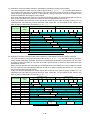
Contact output
functions
*2
Energy saving
collaboration
functions
Data output
functions
(Up to 8 in PLC
and GOT)
Item
Output destination
Output points
System
Upper/lower limit alarm
Energy plan value
monitoring
Specific consumption target
value monitoring
Operating status monitoring
Demand alarm
Demand control
connection destination
Up to 32 points
Up to 5 points
Up to 12 points
Air-conditioner
Up to 10
Output destination
Output
Current data
contents
(Online measuring
point)
Device of PLC/GOT
Data for up to 8groups (255 points max.) can be
outputted.
Up to 32 points output per group (2 words device 1
point)
Data for up to 8groups (255 points max.) can be
outputted.
Up to 32 points output per group (1 word device 16
points)
Output the following data with 30 words (fixed)
・Control device (1 word device)
・Healty (1 word device)
・Current time
(Year/month/day/hour/minute/second: Each 1 word
device)
・Integrated value of consumption (2 words device)
・Current demand (2 words device)
・Predicted demand (2 words device)
・Adjusted electrical power (2 words device)
・Permissible power (2 words device)
・Previous demand (2 words device)
・Remaining time (1 word device)
・Alarm state (1 word device)
・Load control state(1 word device)
・Demand target value (2 words device)
・CVT ratio (2 words device)
・Alarm type (1 word device)
・Integrated value of consumption: Number of
decimal digits (1 word device)
・Current demand: Number of decimal digits (1 word
device)
Collected at 1-minute or 5-minute intervals.
Collected on the hour or on the half-hour.
Collected on the specified hour (at 00 minutes), once
every day
Collected on the specified hour of the specified day
(at 00 minutes), once every month
Collected on the specified demand time limit
(15/30/60 minutes)
Collected on the specified hour (at 00 minutes), once
every day
Demand value is Max. of a day
Collected on the specified hour of the specified day
(at 00 minutes), once every month
Demand value is Max. of a month
Demand
information
Zoom
Daily
Monthly
Annual
Demand(daily)
Demand(monthly)
Demand(annual)
Remarks
Up to 32 points if
CC-Link remote I/O
only
Include in the
number of Output
points.
Up to 32 points
Number of connection
Measurement
error information
Logging
function
Specification
Internal output unit (up to 16 points),
CC-Link Remote I/O (up to 32 points)
Up to 32 points (Separate from all measuring points)
Up to 32 points
Up to 32 points
Up to 32 points
1-9
Send the energy
saving level and
emergency stop
order.
Either of PLC and
GOT can be output.
Item
Calculation
function
Daily
Virtual calculation
points
*3
Specific
consumption
points
*3
Equipment
efficiency
Monthly
*3
Annual
*3
Virtual measuring
point
Specific
consumption
measuring point
Virtual measuring
point
Specific
consumption
measuring point
Specification
Computed from the data
Four arithmetic computations
collected on the hour or
with parentheses can be
on the half-hour
performed on up to 16
arithmetic elements.
A virtual calculation point cannot
be registered within another
virtual calculation point. (Only
normal measuring points can be
registered.)
Energy amount (measuring
point or virtual calculation point)
is divided by production amount
(measuring point or virtual
calculation point).
Quality = Number of
non-defective products /
Number of processed products
Performance
= (Standard cycle time ×
Number of processed
products) / (Loading time Downtime)
Availability
= (Loading time - Downtime) /
Loading time
Overall equipment efficiency
= Availability × Performance ×
Quality
Computed from the data
Same as daily
collected at the logging time
once every day
Same as daily
Computed from the data
collected at the logging time
once every month
Remarks
Virtual measuring
point can not
register to the
arithmetic
expression of
virtual measuring
point.
Same as daily
Same as daily
*2 Contact output is possible up to 32 points by using internal output unit (up to 16 points) and CC-Link remote I/O.
In addition, contact output of the following is possible within 32 points.
(Error information, Upper/lower limit monitoring, Energy plan value monitoring, Specific consumption target value
monitoring, Operating status monitoring, Demand alarm, and Demand control.)
Number of output points are up to 32 points even if contact output is CC-Link remote I/O only.
*3 Calculation accuracy of the virtual measuring point and the specific consumption measuring point, can be selected
from [Integer], [1 digit], [2 digits], [3 digits], [4 digits], and [5 digits] (the number of digits after the decimal point).
1-10
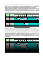
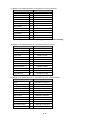
Saving
function
Item
Zoom (1 minute)
Zoom (5 minutes)
Daily
Monthly
Annual
Virtual (daily)
Virtual (Monthly)
Virtual (Annual)
Specific consumption
(daily)
Specific consumption
(Monthly)
Specific consumption
(Annual)
Equipment (daily)
Operation history
System log
Demand (daily)
Demand (Monthly)
Demand (Annual)
Demand alarm and
control history
Deleting function
Specification
Data for 62 days
1-hour data is saved in one file. (Data at 1-minute intervals from
one hour (at 00 minutes) to the next hour (at 00 minutes))
Data for 14 days
1-hour data is saved in one file. (Data at 5-minute intervals from
one hour (at 00 minutes) to the next hour (at 00 minutes))
Data for 186 days
1-day data is saved in one file. (Data at 30-minute or 1-hour
intervals from one day (at 00:00) to the next day (at 00:00))
Data for 60 months
1-month data is saved in one file. (Data at 1-day intervals from the
1st day of one month to the 1st day of the next month)
Data for 5 years
1-year data is saved in one file. (Data at 1-month intervals from
January of one year to January of the next year)
Data for 186 days
1-day data is saved in one file. (Data at 30-minute or 1-hour
intervals from one day (at 00:00) to the next day (at 00:00))
Data for 186 days
1-day data is saved in one file. (Data at 30-minute or 1-hour
intervals from one day (at 00:00) to the next day (at 00:00))
Data for 5 years
1-year data is saved in one file. (Data at 1-month intervals from
January of one year to January of the next year)
Data for 186 days
1-day data is saved in one file. (Data at 30-minute or 1-hour
intervals from one day (at 00:00) to the next day (at 00:00))
Operation monitoring information is saved in operation history data
files. (64 KB × 4 × Number of operation monitoring points)
System error information is saved in system log files. (256 KB × 8)
Data for 186 days
1-day data is saved in one file. (Data at 15-minute, 30-minute or
1-hour intervals from one day (at 00:00) to the next day (at 00:00))
Data for 60 months
1-month data is saved in one file. (Data at 1-day intervals from the
1st day of one month to the 1st day of the next month)
Data for 5 years
1-year data is saved in one file. (Data at 1-month intervals from
January of one year to January of the next year)
Record the occurrence/restore of the alarm, ON/OFF of the alarm
output, and ON/OFF of the control output to the demand
alarm/control history data file.
(128KB×62 files)
Logging data files are deleted when their storage period expires.
1-11
Remarks
Saved in the
CompactFlash
memory card.
Transfer
functions
Item
Zoom (1 minute)
Zoom (5 minutes)
Daily
Monthly
Annual
Virtual (daily)
Virtual (Monthly)
Virtual (Annual)
Specific consumption
(daily)
Specific consumption
(Monthly)
Specific consumption
(Annual)
Equipment (daily)
Operation history
System log
Demand (daily)
Demand (Monthly)
Demand (Annual)
Server
function
Demand alarm and control
history
Web server
FTP server
Client
function
FTP client *5
SMTP client *5
SNTP client *5
HTTP client
Specification
1-hour data is transferred once every hour.
1-hour data is transferred once every hour.
Data of the day is transferred once every hour.
Data of the month is transferred at the specified time, once
every day.
Data of the year is transferred at the specified time, once
every month.
Data of the day is transferred once every hour.
Data of the month is transferred at the specified time, once
every day.
Data of the year is transferred at the specified time, once
every month.
Data of the day is transferred once every hour.
Remarks
Data is
automatically
transferred to a
designated FTP
server.
*4
Data of the month is transferred at the specified time, once
every day.
Data of the year is transferred at the specified time, once
every month.
Data of the day is transferred once every hour.
Updated operation history files are transferred once every
hour.
The latest data is transferred once every hour.
Data of the day is transferred once every hour.
Data of the month is transferred at the specified time, once
every day.
Data of the year is transferred at the specified time, once
every month.
The latest data is transferred once every hour.
Communicates with up to 5 clients simultaneously.
Web browsers are used to view data.
Communicates with 2 clients.
Transfers files via FTP in response to a command request
from a client.
Communicates with one server.
Automatically transfers data files to the FTP server.
(A path can be specified for each type.)
Communicates with one SMTP server.
Notifies upper and lower limit errors and operation
monitoring information by email.
Communicates with one SNTP server.
Acquires and configures the time information periodically.
Communication with the air-conditioner of up to 10
Carry out the notification of the emergency stop control and
Energy saving level change.
*4 Because logging data file of the today or the current month will be overwritten, file transfer is unable when the data
file in the FTP server is being used in other application S/W. Also, when the data file is set overwrite protection in the
FTP server, cannot transfer.
*5 When the FTP server is stopped or LAN communication is abnormal, can not be transferred and retransmission.
Also, since any data in the FTP server is not deleted automatically, clean up the server by deleting the data at regular
intervals.
1-12
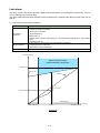
Display
function
Item
Real-ti
Demand value
me
Monitor
Monitor
Current value
Monitor
Contact output
Monitor
Specification
Display the following information about the demand control
<Demand trend (today)>
Bar graph: Current demand, Predicted demand,
Demand (today)
<Demand load curves>
Line graph: Current demand, Predicted demand,
Target demand value, Fixed alarm value
<Demand information>
Value: Current demand, Predicted demand, Adjusted
power,
Permissible power, Limit alarm value,
Target demand value,
Fixed/Limit alarm value
Alarm status: Level 1/Level 2/Limit(Fixed)/
Energy saving level
Time information: Time, Remaining time, Time zone
Daily pattern
Control status: Control type, Priority, ON/OFF
Display update interval (automatic update): 10 sec
・Select the display type from the [Any Point] or the [Group]
・Select the view type from the [Accumulated value], [Hourly
diff.], [Daily diff.], [Monthly diff.]
<Analog value>
Display the current measuring data
<Electric energy and pulses>
Accumulated value: Present meter indicated value
Hourly diff.: Accumulated value from the previous hour to
the present hour
Daily diff.: Accumulated logging time from the previous
month to the present month
Monthly diff.: Accumulated logging time from the previous
year to the present year
<Demand measuring point>
Current demand(Whole day, Time zone 1 - 10)
: Present measuring data
Electric energy(Whole day, Time zone 1 - 10)
Accumulated value: Current integrated value
Hourly diff.: Accumulated value from the previous hour to
the present hour
Daily diff.: Accumulated logging time from the previous
month to the present month
Monthly diff.: Accumulated logging time from the previous
year to the present year
Displays up to 10 measuring points in one screen.
Display update interval (automatic update): 10 sec
Display the contact output status of internal output unit and
CC-Link remote I/O, contact control is possible by password
authentication.
<Contact control>
Alarm output: ON -> OFF only
Control output: ON/OFF
The number of display points: 32
Display update interval (automatic update): 10 sec
1-13
Remarks
Display
function
Item
Graph
display
Demand
trend Graph
Specification
Display the demand trend graph
Display interval: Select from Daily/Monthly/Annual
Daily
Measuring
point
comparison
Graph
Display the demand for each demand time in
1 day.
Bar graph: Demand(for each time zone)
Line graph: Target demand value,
Fixed alarm value
Monthly
Display the max. demand value of a day for
(Max demand of
1 month.
day)
Bar graph: Max demand of day(for each time
zone)
Annual
Display the max. demand value of a month
(Max demand of
for 13 months.
month)
Bar graph: Max demand of month(for each
time zone)
Line graph: Max
List: Demand time limit when max demand
of month is occurred(for each time zone)
・Display the multiple measuring points data of the specified
display intervals(Zoom/Daily/Monthly/Annual) and display date
and time.
・Display the measuring point comparison graph of max 12
measuring points in 1 screen.(The number of graph up to 10)
(Display the measuring point alongside in the same graph or
vertical row)
・Display the graph of measuring point that was registered to the
display list file.(Up to 32 files)
Optionally, can be added(deleted) to(from) the display list.
The following measuring point can be selected
・Electric energy and pulses
・Analog value
・Analog value(power factor)
・Virtual measuring point
・Demand measuring point
Electric energy
(Whole day, Time zone 1 - 10)
Demand
(Whole day, Time zone 1 - 10)
Display update interval (automatic update):
Zoom(1 min)/Zoom(5 min)/Daily … 1 min
Monthly/Annual … 1 hour
Date
comparison
Graph
・Display the measuring point with the date comparison
・Display in the specified display intervals
(Zoom/Daily/Monthly/Annual)
・Display the date comparison graph of max 10 measuring points
in 1 screen.(The number of graph up to 10)
・Display the graph of measuring point that was registered to the
display list file.(Up to 32 files)
Optionally, can be added(deleted) to(from) the display list.
The following measuring point can be selected
・Electric energy and pulses
・Demand measuring point
Electric energy
・Analog value
(Whole day, Time zone 1 - 10)
・Analog value(power factor)
Demand
・Virtual measuring point
(Whole day, Time zone 1 - 10)
Display update interval (automatic update):
Zoom(1 min)/Zoom(5 min)/Daily … 1 min
Monthly/Annual … 1 hour
1-14
Remarks
Display
functions
Item
Graph
display
Specific
consumption
Graph
Specification
Display the specific consumption graph
Display interval: Select from Daily/Weekly/Monthly/Annual
Display update cycle (Automatic graph update):
Daily/Weekly … 1 minute
Monthly/Annual … 1 hour
Daily
Bar graph: Production and energy amount on
the hour or on the half-hour
Line graph: Accumulated specific consumption
and energy amount on the hour or on the
half-hour
Weekly
Bar graph: Production and energy amount on
the hour or on the half-hour
Line graph: Accumulated specific consumption
and energy amount on the hour or
on the half-hour
Monthly
Bar graph: Production and energy amount on
the 1-day intervals
Line graph: Accumulated specific consumption
and energy amount on the 1-day intervals
Annual
Equipment graph
Bar graph: Production and energy amount on
the 1-month intervals
Line graph: Accumulated specific consumption
and energy amount on the 1-month intervals
Display the Equipment graph
Display interval: daily (fixed)
<Equipment group graph>
Bar graph: Daily accumulated number of defective
products
Line graph:Daily accumulated downtime
<Equipment efficiency graph>
Bar graph: Availability/Performance/Quality on the hour or
on the half-hour
Line graph: Overall equipment efficiency on the hour or on
the half-hour
<Equipment detail graphs 1 to 10>
Bar graph: Usage amount on the hour or on the half-hour
Line graph: Accumulated usage amount
1-15
Remarks
Displays 1-day data
on the hour or on
the half-hour.
Displays 2 days of
data simultaneously.
Displays 7-day data
on the hour or on
the half-hour.
Displays 7 days of
data starting from
the specified date
serially.
Displays 1-month
data at 1-day
intervals.
Displays 2 months
of data
simultaneously.
Displays 1-year data
at 1-month intervals.
Displays 2 years of
data simultaneously.
Displays data for the
number of
registered
equipment groups
simultaneously.
Displays 1-day data
on the hour or on
the half-hour.
A detail equipment
graph shows data
for the number of
points registered in
the equipment item
details.
Display
functions
Item
Data file
Demand data
Measuring point
data
Virtual calc. point
data
Sp. Cons. data
Equipment data
Operation history
data
System log
Specification
Display the following file
<Annual(Max demand of each month)>
Contains 1-year data logged at 1-month intervals
<Monthly(Max demand of day)>
Contains 1-month data logged on the specified hour
every day
<Daily>
Contains 1-day data logged on the hour or on the
half-hour
<Demand alarm and control log>
Record the history of the occurrence/restore of Level
1, Level 2, Limit/Fixed
Record the history of the demand control ON/OFF
128KB×62files
Display the following file
<Annual>
Contains 1-year data logged at 1-month intervals
<Monthly>
Contains 1-month data logged on the specified hour
every day
<Daily>
Contains 1-day data logged on the hour or on the
half-hour
<Zoom (5 minutes)>
Contains 1-hour data logged at 5-minutes intervals
<Zoom (1 minute)>
Contains 1-hour data logged at 1-minute intervals
Display the following file
<Annual>
Contains 1-year data logged at 1-month intervals
<Monthly>
Contains 1-month data logged on the specified hour
every day
<Daily>
Contains 1-day data logged on the hour or on the
half-hour
Display the following file
<Annual>
Contains 1-year data logged at 1-month intervals
<Monthly>
Contains 1-month data logged on the specified hour
every day
<Daily>
Contains 1-day data logged on the hour or on the
half-hour
Contains 1-day data logged on the hour or on the half-hour
Contains a log of ON/OFF states of operation monitoring points
64 KB × 4
Saved in a separate file for each operation monitoring point
Contains a log of occurrence and recovery of
measurement errors, upper and lower limit errors, etc.
256 KB × 8
1-16
Remarks
Display
functions
Item
Setting
Setting of
of
Demand control
Measuri
ng point
list
Measuring point
list
Setting of
Planned value
Data output list
Contact output
list
Email
notification list
File transfer
Time adjustment
Demand alarm occurrence
display
Specification
Display the following settings
・Demand basic setting
・Alarm setting
・Demand control setting
Time zone setting
Display the setting of Time zone
name and Daily pattern
Calendar setting
Display the following settings
・Time zone setting
・Daily pattern setting
・Calendar setting
Energy saving level
Display the following settings
monito setting
・Energy saving level monitor setting
・Energy saving level alarm setting
・Air-controller connection setting
Electric energy and
Displays the settings of measuring
pulses
points (electric energy and pulses)
Analog value
Displays the settings of measuring
points (analog values)
Virtual
Displays the settings of virtual
calculation points
Specific consumption
Displays the settings of specific
consumption points
Operation monitoring
Displays the settings of operation
monitoring points
Equipment
Displays the settings of equipment
Group
Displays the details of groups
registered
Equipment group
Displays the details of equipment
groups registered
Energy planned value (Jan. - Dec.)
Energy planned value (Apr. - Mar.)
Target value of specific consumption
Data output group list
Displays the data output setting
Demand setting
Data output
Displays the data output setting
(Demand control)
(Demand control)
Displays the settings of contact output
Displays the settings of e-mail notification
Displays the settings of file transfer
Displays the settings of automatic time adjustment
Displays when the demand alarm occurs
1-17
Remarks
Surveillance
functions
Item
System log
Specifications
Demand control
Email
notificati
on
*6
*7
Boot notification
Error notification
Upper and lower
limit monitoring
Operation
monitoring
notification
Energy planned
value monitoring
notification
Specific
consumption
planned value
monitoring
notification
Regular report
Daily
Weekly
Monthly
Remarks
Contains a log of occurrence and recovery of measurement errors, upper and
lower limit errors, etc.
256 KB × 8
Level 1 alarm / Level 2 alarm / Limit alarm / Fixed alarm / demand control unit
error of the alarm state is monitored at 10-second intervals
Sent to the
Energy Saving Data Collecting Server is booted up.
designated
Error occurs during reading/writing to CompactFlash
address for each
memory card.
event (one
Measurement error occurs the specified number of times
address for each
consecutively or normal measurement recovers.
event).
Monitored at 10-second intervals.
Number of times that can be specified: 1 to 18 (depending
on the settings)
File transfer error occurs.
Monitored at 1-hour intervals.
Automatic time adjustment error occurs.
Monitored at specified intervals (daily/weekly/monthly).
Data output error occurs the specified number of times
consecutively or normal output recovers.
Monitored at 1-minute intervals.
Number of times that can be specified: 1 to 3 (depending on
the settings)
Battery error occurs.
Monitored at 1-minute intervals.
Sent to the
Upper and lower limit error occurs on a measuring point.
designated
32 points max.
address for each
Monitored at 10-second intervals.
event (one
The status of an operation monitoring point changes.
address for each
32 points max.
event).
Monitored at 10-second intervals.
Energy planned value (accumulated value per day) is
exceeded.
255 points max.
Monitored at the monthly logging time (at 1-day intervals).
Specific consumption planned value is exceeded.
64 points max.
Monitored every hour on the hour or on the half-hour.
Specified messages.
Up to 128 characters in one message.
Up to 8 messages.
On the specified hour, once every day
On the specified hour of the specified day, once every week
On the specified hour of the specified day, once every
month
Demand
notification
Each message is
sent to its
designated
address at its
designated time
(one sending time
and receiving
address for each
message).
Send to specified
destination for
each event
(One destination
for each event)
Demand control alarm occurred and restored
(Level1alarm / Level 2 alarm / Limit, Fixed alarm /
Battery error (demand control unit) / Outside
synchronism error / Demand control error)
Monitored at 10-second intervals.
*6 Mail notification is only function of sending mail data (destination/message) to mail server (SMTP).
Mail server receives the data, and sends the message (e-mail) to each destination.
*7 Timing to actually receive will depend on the situation of the mail server processing and communication network.
1-18
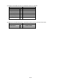
Control
functions
Item
Demand control
Manual control
Calendar setting management function
Maintenance
functions
Planned value/Target
value setting
Time setting
Specifications
Control the circuit that was set the priority order, as the
predicted demand does not exceed the target demand.
(up to 12 circuits)
Demand control type: The following 6 patterns
Cyclic - Reclosing
Cyclic - Reclosing after Demand time limit
Cyclic - Reclosing after Reclosing interval
Priority order - Reclosing
Priority order - Reclosing after Demand time limit
Priority cyclic - Reclosing
By the password authentication in real-time display
screen of contact output monitor, manual control is
possible (alarm OFF control, ON/OFF control of
demand controlled circuit).
Demand management is possible by setting the time zone
switching calendar (up to 24 months)
Time zone: up to 10, Daily pattern: up to 40
Specifies monthly planned values and specific
consumption planned values for the year (fiscal year).
Reads and sets the current date and time.
1-19
Remarks
Demand
setting
functions
Item
Normal
Alarm and
Control
Circuit name
VCT ratio
Pulse constant
value
Multiplying factor
Number of
digits
Multiplying
factor
Demand time limit
adjustment type
Demand time limit
Alarm/Control
mask time
Alarm type
Management
based on calendar
Settings for each
Time zone
Checked/Not checked
4-6
Default: Not checked
Default: 5
1 - 100000
Default: 1
Initial TS/
External pulse signal
15/30/60(minutes)
0 - n(minutes) n=demand
time limit
Limit alarm/Fixed alarm
Checked/Not checked
Default:Initial TS
Default: Limit alarm
Default: Not checked
Set the following to the time zone 1 - 10
Target demand value, Base power, Fixed alarm value
0.0 - 999999.9(kW)
Default: 300.0
0.0 - 99999.9(kW)
0.0 - 999999.9(kW)
8 characters
Default: 0.0
Default: 240.0
Default: Whole day
Demand control
type
Selected from the following
・Cyclic - Reclosing
・Cyclic - Reclosing after Demand time limit
・Cyclic - Reclosing after Reclosing interval
・Priority order - Reclosing
・Priority order - Reclosing after Demand time limit
・Priority cyclic - Reclosing
Up to 12 circuits
Invalid, 1 - 12
Default: Invalid
0.0 - 99999.9(kW)
Default: 0.0
1 - n(minutes)
Default: 5
n=demand time limit
Up to 12 circuits
Manual control
Daily pattern
setting
Calendar setting
Remarks
Default: 30
Default: 6
Target demand
value
Base power
Fixed alarm value
Time zone name
Number of circuits
Priority order
Control capacity
Reclosing interval
Calendar
Specifications
Input the circuit name to monitor
1 - 100000
Default: 600
1 - 50000(pulse/kWh)
Default: 50000
Set the time zone 1-10 to the daily pattern 1-40 with each
demand time limit
Set the daily pattern until December 31 of following year
from the set year.
1-20
If manual
control, requires
a password input
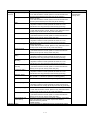
Data collecting
settings
functions
Item
CC-Link terminal
Specifications
Set the following contents
Registration of terminal to be connected
Carry out the normal setting and station No.
registration for each terminal
Set the following contents
Register the PLC/GOT to be connected
Communication method (Ethernet direct, Convert
Ethernet / serial)
IP address, Port No., and Station No. of the device to
be connected
Set the measuring element to collect
If the PLC/GOT
Specify the device for each registered equipment,
and get the word data or bit data
Set the arithmetic expressions with parentheses
Remarks
Up to 42 units can be
registered
Specific consumption
Register the specific consumption
* Set the display of the specific consumption
Up to 64 points can be
registered
Equipment
Set the following contents
Standard cycle time
Operating time
Quality rate
Required when
calculating the
equipment efficiency
Up to 42 points can be
registered
Save
Write
Save the contents that have been registered by the
setting software
Write the project to the EcoWebServerIII
Read
Read the project of the EcoWebServerIII
Collate
Collate the project of EcoWebServerIII and setting
software.
PLC/GOT
Measuring point
Virtual
Project
management
functions
1-21
Up to 8 units can be
registered
Up to 255 points can
be registered
Up to 128 points can
be registered
Login ID and
password is required
Default
Login ID: ecoV
Password: ecopass
Setting
functions
Item
IP address setting
Time setting
Auto time adjustment
Logging time setting
Login ID
Password
For
maintenance
For getting data
For system
management
Output
setting
functions
Test/adjustm
ent function
Data output setting
Data output setting
(demand control)
Contact output setting
Mail notification setting
File transfer setting
Energy saving cooperation
setting
Confirming the terminal
connection
Confirming the contact output
Confirming mail send
Confirming file transfer
Confirming air-conditioner
connection
Integration value setting
Collect data
Delete data
Reset
Specifications
Set the following contents
CH1
IP address
Default: 192.168.10.1
Subnet mask
Default: 255.255.255.0
Default gateway
Default: None
DNS setting
Default: None
CH2
IP address
Default: 192.168.3.1
Subnet mask
Default: 255.255.255.0
Default gateway
Default: None
Read and write clock of EcoWebServerIII
Set the following contents
IP address registration of SNTP server
Time to carry out the auto time adjustment
Set the following contents
Daily log
Default: half
Monthly log
Default: 0H
Annual log
Default: 1D 0H
Setting the password
Setting the loggin ID and password
Setting the loggin ID and password
Set the measuring data to be output to the PLC/GOT
Set the demand control data to be output to the
PLC/GOT
Set the contact output destination of the alarm output
and demand control
Set the mail notification destination
Set the file transfer destination
Set the IP address of the air conditioning controller to
be connected
Confirm the connection status of the registered
terminal
Confirm the operation of contact output
Confirm the operation of mail send
Confirm the operation of file transfer
Confirm the operation of Energy saving level send
Set the metric indication value to EcoWebServerIII
Collect the csv file of EcoWebServerIII
Delete the data in the EcoWebServerIII
Reset the EcoWebServerIII
1-22
Remarks
Default
Password: ecopass
Default
Loggin ID: guest
Password: user
Default
Loggin ID: ecoV
Password: ecopass
2. Before use
This chapter describes the part names and functions of EcoWebServerIII as well as the recommended system
environment, the installation of the Setting software, the uninstallation of the Setting software, the upgrade of
the Setting software, and the relevant settings of PCs, which are essential for using the Setting software.
2.1. Recommended system environment
The system environment requirements for this software to properly operate as follows:
Item
System environment OS
(basic software)
CPU
*1
Memory
*1
Hard disk
CD drive
*2
Display resolution
*3
Display color
Input device
English input system
External interface
Web browser
Java plug-in
*1
*2
*3
*4
*4
Description
®
Microsoft Windows XP Professional (32 bits) (English version) SP3
®
Microsoft Windows Vista Business (32 bits) (English version) SP2
®
Microsoft Windows 7 Professional (32 bits, 64bits) (English version) SP1
®
Microsoft Windows 8.1 Pro (32bits, 64 bits) (English version)
®
Pentium processor running at 1 GHz or higher, or compatible microprocessor
(DOS/V compatible)
1GB or more
When the data collected by EcoWebServerIII save in the PC, requires its
capacity.
One or more drives (required in the software installation)
1280 x 1024 pixels or more
65536 colors or more
A mouse and a keyboard
The system included in OS (English version only)
A 10BASE-T/100BASE-TX or CompactFlash card reader (required when
performing the write/read/check of projects via a drive)
®
Internet Explorer 7 (32 bits) or
®
Internet Explorer 8 (32 bits) or
®
Internet Explorer 9 (32 bits) or
®
Internet Explorer 10 (32 bits) or
®
Internet Explorer 11 (32 bits) or
TM
Oracle Java 7 JRE 7 (32-bit)
TM
Oracle Java 6 JRE 6 (32-bit)
Note that the required memory and free space of hard disk are varied depending on the system environment.
Use the default screen font size of "Small Fonts (standard). "If the font size is changed to "Large Fonts" or "Extra Large Fonts," the
characters and images may not be displayed properly, and some portions of the window may be out of the screen.
Although this software can be used in the 256-color mode, icons and other items cannot be displayed properly.
In the environments where Internet Explorer® is not installed, the communication with EcoWebServerIII may not be performed.
2-1
2.2. Glossary
This following defines key terms used in this document.
Item
Project
Terminal
PLC
Measuring point
Group
Operation monitoring
measuring point
Contact output
Virtual measuring point
Specific consumption
measuring point
Equipment
Equipment group
Daily data
Weekly data
Monthly data
Annual data
Zoom data
Virtual data (daily)
Virtual data (monthly)
Description
Refers to a set value that is used for the operation of EcoWebServerIII
Refers to a CC-Link terminal or CC-Link master/local unit (local station). A maximum of 64
terminals can be registered.
Refers to PLC used by EcoWebServerIII to acquire the computer link communication data
using Ethernet communication or an Ethernet/Serial adaptor cable. Up to 32 PLCs can be
registered.
Refers to an item collected from a terminal. A maximum of 255 points can be
registered.
Refers to a group of measuring points. A maximum of 32 groups can be registered.
Refers to a measuring point for recording the operation status of equipment by
monitoring digital input signals. Up to 32 of 255 measuring points can be registered.
Refers to output when an event such as an error occurs in EcoWebServerIII. Up to 32
contact output points can be registered.
Refers to a measuring point for which the computation result between measuring
points is used as virtual measurement data. A maximum of 128 measuring points
(excluding the 255 measuring points) can be registered.
Refers to a measuring point for which the result of dividing energy amount by
production amount is used as measurement data. A maximum of 64 measuring
points (excluding the 255 measuring points) can be registered.
Refers to a measuring point for recording an equipment status such as equipment
efficiency. A maximum of 42 measuring points can be registered.
Refers to a group of equipment measuring points. A maximum of 42 groups can be
registered.
Refers to the data of a measuring point collected on the hour or on the half-hour for 1
day.
Refers to the data of a measuring point collected on the hour or on the half-hour for 7
days.
Refers to the data of a measuring point collected at 1-day intervals for 1 month.
Refers to the data of a measuring point collected at 1-month intervals for 1 year.
Refers to the data of a measuring point collected at 1-minute or 5-minute intervals for
1 hour.
Refers to the data of a virtual measuring point collected on the hour or on the
half-hour for 1 day.
Refers to the data of a virtual measuring point collected at 1-day intervals for 1
month.
Virtual data (annual)
Refers to the data of a virtual measuring point collected at 1-month intervals for 1 year.
Specific consumption data
(daily)
Refers to the data of a specific consumption measuring point collected on the hour or
on the half-hour for 1 day.
Specific consumption data
(monthly)
Specific consumption data
(annual)
Refers to the data of a specific consumption measuring point collected at 1-day intervals
for 1 month.
Refers to the data of a specific consumption measuring point collected at 1-month
intervals for 1 year.
Operation history data
Refers to the data recorded when the status of an operation monitoring point is
changed.
Demand data (daily)
Demand data (monthly)
Refers to demand data collected at the set demand timing for 1-day.
Refers to one month's worth of data recording the demand data collected daily at the
designated time and the daily maximum demand.
Refers to one year's worth of data recording the demand data collected monthly at the
designated time and the monthly maximum demand.
Demand data (annual)
2-2
Item
Description
Demand alarm and control Refers to a record of the demand alarm occurrence/reset and demand control.
history data
System log
Refers to the data of events such as errors that occur in EcoWebServerIII.
Maintenance password
Refers to a password required to reset EcoWebServerIII or to set dates and energy planned
values/target Specific consumptions.
Data acquisition login ID
Refers to an account required to collect EcoWebServerIII data from FTP clients, and gives
and password
read-only permission.
System administration
Refers to an account required for the system administration of EcoWebServerIII, and gives
login ID and password
read and write permissions for all files.
FTP server
Refers to a server that provides files on the Internet (via LAN).
FTP stands for File Transfer Protocol.
SMTP server
Refers to a mail server that performs the transmission process of email to distribute it to
other mail servers on the Internet (via LAN).
SMTP stands for Simple Mail Transfer Protocol.
SNTP server
Refers to a server that provides time information to clients on the network.
SNTP stands for Simple Network Time Protocol.
Domain name
Refers to the identifier of a computer or computer group that is connected to the Internet (via
LAN).
DNS server
Refers to a server that converts domain names into IP addresses on the Internet (via LAN).
DNS stands for Domain Name System.
2-3
2.3. Installing the software
The setting software can be easily set up and launched by using the dedicated installer.
When setting up the EcoWebServerIII setting software for the first time, be sure to read this chapter before
performing the set-up.
To perform the set-up, you must log in with the administrator privileges.
*1 The operations and dialog boxes may be varied depending on the type of OS on your PC or the operating
environment.
MES3-255C-DM-EN is used in the following operations, but this also applies MES3-255C-EN.
*2 If an older version of the EcoWebServerIII setting software is already installed, see "2.5 Upgrading the
software," and upgrade the setting software.
1
Inserting the CD and launching the installer
(1) Insert the EcoWebServerIII setting software set-up CD-ROM into the CD drive on your PC.
The web site below will be displayed. Click the setting software to install.
Click Setting Software.
* If the installer is not automatically launched, open the CD drive with Explorer, and double-click
[ReadMe.html] in the root folder to run it.
(2) Security warning screen will appear so click [Execute]. The installation will start.
Click the [Cancel] button to cancel the installation.
2-4
(3) The [Welcome to the InstallShield Wizard for Model MES3-255C-DM-EN Setting software ver2] dialog box
is displayed.
Click the [Next] button. Click the [Cancel] button to cancel the installation.
Remarks
If the installer is run when the EcoWebServerIII setting software Ver. 2 is already installed, the [Uninstall the
application] confirmation is displayed.
To reinstall, uninstall the software with the following procedure, and then install again.
Click the [Yes] button to uninstall the EcoWebServerIII setting software Ver. 2. Click the [No] button to
cancel the uninstallation.
When uninstallation is completed, the [Uninstall complete] screen appears.
2 Checking the license agreement
The [License Agreement] dialog box is displayed.
When accepting the license agreement, click [Yes] button.
If you do not accept the license agreement, click the [No] button to cancel the installation.
2-5
3
Installing the software
(1) The [Choose Destination Location] dialog box is displayed.
*1 The default installation locations of each product are listed below.
Product model
Installation location
MES3-255C-EN
C:\Mitsubishi\mes3CEn_ver2\
MES3-255C-DM-EN
C:\Mitsubishi\mes3CDmEn_ver2\
*2 The installation location can be changed by clicking the [Browse…] button to specify the desired folder.
However, we recommend that you use the default installation location in normal conditions.
(2) Click the [Next] button to start the installation.
Click the [Cancel] button to cancel the installation.
(3) When the installation is completed, the [InstallShield Wizard Completed] dialog box is displayed. Click the
[Finish] button.
* Depending on the operating environment, a message prompting you to restart the computer may be
displayed after the installation is completed. In this case, follow the instruction in the displayed message
to restart the computer.
(4) The installation is completed.
You can launch the setting software from the Windows [Start] menu or the icon on the desktop.
2-6
2.4. Uninstalling the software
If the setting software is no longer needed, you can easily remove the software from your PC by using the
uninstallation function of [Programs and Features].
To perform the uninstallation, you must log in with the administrator privileges.
*1 The operations and dialog boxes may be varied depending on the type of OS on your PC or the
operating environment.
MES3-255C-DM-EN is used in the following operations, but this also applies MES3-255C-EN.
*2 Even if the uninstallation is performed, the created projects are not deleted.
*3 Uninstall after you have finished this software.
1
Uninstalling the software
<Procedures in Windows 7>
(1) Open [Control Panel] of Windows.
(2) Open [Programs] - [Uninstall a program].
2-7
(3) Select the installed setting software, and click [Uninstall].
* When the [User Account Control] dialog box is displayed, click [Continue].
(4) The [Uninstall the application] confirmation message is displayed.
Click the [Yes] button.
Click the [No] button to cancel the uninstallation.
(5) The uninstallation is performed.
When the uninstallation is completed, the [Uninstall Completed] dialog box is displayed.
Click the [Close] button.
2-8
2.5. Upgrading the software
This section describes the procedures when upgrading from an older version (EcoWebServerIII setting
software Ver1) to Ver2.
* EcoWebServerIII setting software Ver1 and Ver2 can be installed on the same PC.
(How to check the version information? Refer to "4.1 Operating Procedures: Starting/exiting the
Setting software, Remarks.")
1
Backing up the setting project of setting software(Ver1.2.1 or earlier)
Refer to "4.2.6 Backing up projects" and backup the setting project of older version (Ver1).
* In advance, reading from EcoWebServerIII Ver1 and to save, using the setting software Ver1.
2
Installing EcoWebServerIII setting software Ver2
Refer to "2.3 Installing the software" and install the EcoWebServerIII setting software Ver2.
3
Restoring an older setting project using EcoWebServerIII
setting software Ver2.
Refer to "4.2.7 Restoring projects " and restore the setting project that backed up in step 1.
After the restore, please check the following.
1) Confirm the body registration contents of mail notification setting
2) Confirm the measurement point registration contents of contact output
After the restore, checking the ID240 - 255 of a list of registered measuring points before saving
project.
When exists the terminal name of measuring point is"Internal Output Unit" in the ID240 - 255,
save the project after deleting the measuring point (In Ver2, contact output is not included in the
measuring point).
4
Writing the project to EcoWebServerIII Ver2.
Refer to "4.6.2 Project writing" and write the project to EcoWebServerIII Ver2.
Remarks
Do not read project from EcoWebServerIII Ver1 using the setting software Ver2.
Perform the above steps surely.
2-9
3. Flow of settings
This chapter describes the flow of setting before operating EcoWebServerIII.
3.1. Procedures for initial settings (Common)
Initial settings for EcoWebServerIII are as following.
1
Performing the installation and wiring of the unit
Please wire the measurement to EcoWebServerIII, see details in manual – Hardware. Connect the measuring
equipment and EcoWebServerIII.
When using the EcoWebServerIII with demand control function, connect the electric energy pulse signal from
the dedicated CT for pulse detection, pulse detector (pulse converter), or electronic electricity meter.
2
Installation of the EcoWebServerIII setting software
Install the EcoWebServerIII configuration software to set the EcoWebServerIII IP address and time. Refer to
section 2.3 Installing the software" for details on installation.
3
Connecting the personal computer and EcoWebServerIII
(1) Connect the personal computer and EcoWebServerIII
Connect the personal computer equipped with the setting server and the EcoWebServerIII with a LAN
cable. Connect directly with a LAN straight cable or cross cable.
(2) Change the personal computer’s IP address
Change the personal computer's IP address to connect with EcoWebServerIII. The EcoWebServerIII IP
address is set to 192.168.10.1 as the default. Set the personal computer's IP address so this IP address
can be accessed.
1. Take a note of the IP address set in the PC.
IP Address:
Subnet mask:
Default gateway:
.
.
.
.
.
.
.
.
.
2. Change IP address set in the PC according to the IP address (factory setting: 192.168.10.1) set in the
product.
IP address for the product
192.168.10.1
IP address for the PC
IP address: 192.168.10.xx (xx is a value from 2 to 255.)
(For example, change to 192.168.10.10, etc.)
Subnet address: 255.255.255.0
Default gateway: Blank
3-1
4
Setting the EcoWebServerIII IP address
Set the IP address for the EcoWebServerIII with the setting software.
(1) Start the EcoWebServerIII configuration software
■ For CC-Link communication product with demand control function
Open [Start] menu ⇒ [All programs] - [Mitsubishi Energy Management] [EcoWebServerIII(MES3-255C-DM-EN)ver2] - [Model: MES3-255C-DM-EN Setting software]
Or, double-click the [Model MES3-255C-DM-EN Setting software ver2] icon on the desktop.
■ For CC-Link communication product
Open [Start] menu ⇒ [All programs] - [Mitsubishi Energy Management] [EcoWebServerIII(MES3-255C-EN)ver2] - [Model: MES3-255C-EN Setting software]
Or, double-click the [Model MES3-255C-EN Setting software ver2] icon on the desktop.
<Example>
3-2
The Project management dialog box is displayed shortly. When the following dialog box is displayed, the
launch is completed.
* When the [User Account Control] dialog box is displayed in Windows7, click [Yes] to launch the
software.
(2) Creating a new project
On the Project Management dialog box:
Double-click [<Double-click here to register>]
Or,
Select [<Double-click here to register>], and click the [Open] button.
Set the following information on the Creation project dialog box, and click the [OK] button.
Project name
IP address
Subnet mask
Default gateway
Comment
Any
(Set a name for identifying the EcoWebServerIII such as "Factory A" or "Floor B".)
192.168.10.1
(Set the default IP address.)
255.255.255.0
Blank
Any
3-3
(3) Changing the EcoWebServerIII IP address
1.
Click [Options] on the Project Setting dialog box.
2.
Change the IP address at IP Address Settings (New)
(An example to change the IP address to 10.123.234.10 is shown below. Enter the IP address,
subnet mask and default gateway for operations.)
3.
Inputting the maintenance password (The default maintenance password is "ecopass".), and click
the [
] button.
* The default maintenance password is “ecopass”.
Enter the password after change if it was changed.
3-4
4.
A message to confirm the changes appears when the [
] button is clicked.
Click the [Yes] button.
The following message appears when the changes are complete. Click the [OK] button.
*1
*2
*3
EcoWebServerIII is automatically reset after the IP address setting is changed. (The changed IP
address is validated after resetting is complete.)
It may take 1 to 8 minutes for the reset to finish. Wait for the [STA.] LED on the EcoWebServerIII
unit to change to a steady light before starting communication.
The [IP address], [Subnet mask] and [Default gateway] in the project information are also
automatically updated to the new values.
(4) Checking the IP address set in EcoWebServerIII
1.
Open the front cover on the server section, and set the MODE switch to the “STOP” position.
2.
Hold the RESET switch to the “SEL.” position.
3.
After the “CF CARD” LED turns off, turn the RESET switch to the “RES.” position.
4.
After all the LEDs except the “POWER” LED on the power supply section turn off, return the
RESET/SELECT switch to the central position.
5.
Wait until the product starts up and the IP address is displayed on the 7-segment LED at the front.
IP address display (Example of display when CH1 is set to 192.168.10.1 and CH2 is set to
192.168.3.1)
6.
16 進数:C0: C0
Hexadecimal
10 進数:192
Decimal
: 192
16 進数:A8: A8
Hexadecimal
10 進数:168: 168
Decimal
16 進数:0A: 0A
Hexadecimal
10 進数:10: 10
Decimal
16 進数:01 : 01
Hexadecimal
10 進数:1 : 1
Decimal
Hexadecimal
16 進数:C0: C0
Decimal
: 192
10 進数:192
Hexadecimal
: A8
16 進数:A8
Decimal
: 168
10 進数:168
Hexadecimal
16 進数:03: 03
Decimal
10 進数:3 : 3
Hexadecimal
16 進数:01 : 01
Decimal
10 進数:1 : 1
After you finish checking the IP address, turn the MODE/STOP/RUN switch to the “RUN” position.
3-5
5
Setting the EcoWebServerIII time
The EcoWebServerIII time is set to the default state before shipping. Change the time with the following
procedure.
(1) Displaying the [Time] screen
1.
Select [Time] in the tree menu on the EcoWebServerIII [Options] screen.
(2) Selecting and inputting [Setting of date and time]
Set the following items.
3-6
(3) Inputting the maintenance password
Type in the maintenance password (ecopass).
* The default maintenance password is “ecopass”.
Enter the password after change if it was changed.
(4) Changing
1.
A confirmation message appears when the [
] button is clicked. Click the [Yes] button.
2.
When the setting of the date and time are completed, the following message will be displayed.
*EcoWebServerIII with demand monitor function
EcoWebServerIII with demand control function is shipped at the state of the battery OFF of the demand
control unit, the state of clock of the demand control unit is reset, and error occurs.
Therefore, you need to reset the power of the EcoWebServerIII (4.9.11 EcoWebServerIII reset) after time
setting.
Then be timed adjustment (by the TS switch).
3-7
3.2. Setting procedures for starting operation (without demand control
function)
This section describes flow of settings from starting the EcoWebServerIII unit to starting data collection.
1
Data collecting settings step
(1) Measuring data
collection settings
[Basic settings]
(2) Measuring data
collection settings
[Advanced settings]
(3) EcoWebServerIII
configurations
Register the I/O terminal or PLC connected to
the unit, register the measuring elements
collected from the terminal as the measuring
points, and sort into groups.
(a) Register the terminal
(b) Register the PLC/GOT
(c) Register the measuring points
Refer to:
“4.4.1 CC-Link terminal registration"
“4.4.2 PLC/GOT registration"
“4.4.3 Measuring point registration"
Set the options for expanding the scope of
display and analysis. (This can be skipped
when not using the following functions.)
(a) Register the virtual measuring points
(b) Register the specific consumption
measuring points
(c) Register the equipment
Refer to:
“4.5.1 Virtual measuring point
registration"
“4.5.2 Specific consumption measuring
point registration"
“4.5.3 Equipment registration"
“4.5.4 Equipment group registration"
Set when using the automatic time setting
function, or set the logging date and time.
(a) Configure the automatic time settings
(b) Configure the logging date and time
Refer to:
“4.7.3 Auto time settings”
“4.7.4 Logging date/time settings"
Set this when using mail notification or file
transfer. (This can be skipped when not using
the following functions.)
(a) Set the mail notification
(b) Set file transfer
(c) Set contact output
(4) External device
collaboration settings
(5) Saving and writing a
project
Save the set project and write it to the main
unit.
(6) Starting data collection
Start collection of data from each terminal.
3-8
Refer to:
“4.8.4 SMTP server settings”
“4.8.6 EcoWebServerIII error settings”
“4.8.7 Regular report registration"
“4.8.8 Upper/lower limit notification
registration"
“4.8.9 Operating status notification
registration"
“4.8.10 Specific consumption target
value notification registration"
“4.8.11 Energy plan value notification
registration"
“4.8.12 FTP server setting”
“4.8.13 Transfer enable/disable, transfer
destination folder setting”
“4.8.3 Contact output settings”
Refer to:
“4.6.1 Project saving”
“4.6.2 Project writing”
3.3. Setting procedures for starting operation (with demand control
function)
This section describes flow of settings from starting the EcoWebServerIII unit with demand control function to
starting data collection.
1
Configuring demand control settings and data collection
Configure the settings related to demand
control and control
(1) Demand control settings (a) Configure the demand basic settings
(b) Configure the demand alarm and control
settings
Refer to:
“4.3.2 Demand basic settings”
“4.3.3 Demand alarm and control
settings”
Set the time zone name, day pattern and
calendar.
(2) Time zone and calendar (a) Configure the demand alarm and control
settings
settings
(b) Configure the demand calendar settings
Refer to:
“4.3.3 Demand alarm and control
settings”
“4.3.4 Demand calendar settings”
* Refer to the following section for details.
"2 Time zone calendar settings”
(3) Measuring data
collection settings
[Basic settings]
(4) Measuring data
collection settings
[Advanced settings]
(5) EcoWebServerIII
configurations
Register the I/O terminal or PLC connected to
the unit, register the measuring elements
collected from the terminal as the measuring
points, and sort into groups.
(a) Register the terminal
(b) Register the PLC/GOT
(c) Register the measuring points
Refer to:
“4.4.1 CC-Link terminal registration"
“4.4.2 PLC/GOT registration"
“4.4.3 Measuring point group
registration"
Set the options for expanding the scope of
display and analysis. (This can be skipped
when not using the following functions.)
(a) Register the virtual measuring points
(b) Register the specific consumption
measuring points
(c) Register the equipment
Refer to:
“4.5.1 Virtual measuring point
registration "
“4.5.2 Specific consumption
measuring point registration "
“4.5.3 Equipment registration "
“4.5.4 Equipment group registration "
Set when using the automatic time setting
function, or set the logging date and time.
(a) Configure the automatic time settings
(b) Configure the logging date and time
Refer to:
“4.7.3 Auto time settings”
“4.7.4 Logging date/time settings"
* When setting the time to the business
meter, do not set the automatic time setting
function.
3-9
Set this when using mail notification, file
transfer, or demand control. (This can be
skipped when not using the following
functions.)
(a) Set the mail notification
(b) Set file transfer
(c) Set contact output (Set the contact output
for control circuits 1 to 12)
Refer to:
“4.8.4 SMTP server settings”
“4.8.5 Demand notification”
“4.8.6 EcoWebServerIII error notification
settings”
“4.8.7 Regular report registration"
“4.8.8 Upper/lower limit notification
registration"
“4.8.9 Operating status notification
registration"
“4.8.10 Specific consumption target
value notification registration"
“4.8.11 Energy planning value
notification registration"
“4.8.12 FTP server setting”
“4.8.13 Transfer enable/disable,
transfer destination folder setting”
“4.8.3 Contact output settings”
Set this when connecting to air-conditioner.
(a) Set the Web-compatible controller
address
(b) Set the monitoring enable/disable,
monitoring type, and alarm value 1 to 4
Refer to:
“4.8.14 Energy saving level monitor
setting”
“4.8.15 Air-controller connection
settings”
Save the set project and write it to the main
unit.
Refer to:
“4.6.1 Project saving”
“4.6.2 Project writing”
(9) Test and adjustment
Confirm the operation before starting actual
operation.
* Refer to the following section
"3. Test and Adjustment" for details.
(10) Time lag adjustment
Set to the business meter's time lag, and
press the time lag adjustment (TS) switch.※1
(11) Start operation
Start demand control control and collection of
data from each terminal.
(6) External device
collaboration settings
(7) Energy saving
collaboration settings
(8) Saving and writing a
project
*1
The LAN communication will cause a time lag in the time set with the main units setting and setting
the time screen.
After setting the clock, set the time to the time lag display on the business meter, etc., and press
the time lag adjustment (TS) switch.
3-10
2
Setting the time zone and calendar
This section describes the procedures for setting the time zone calendar.
(1) Time zone
name setting
Set (change) the time zone name as needed.
Refer to:
"4.3.3 Demand alarm and control
settings"
Set the pattern of one day's time zone.
Refer to:
"4.3.4 Demand calendar settings"
Set the policy changeover month, and each month's
daily pattern calendar.
Refer to:
"4.3.4 Demand calendar settings"
↓
(2) Day pattern
setting
↓
(3) Calendar
setting
* The calendar can be set backward from the current date and time to the previous policy changeover
month. Up to 24 months can be set. Set the calendar each time the time zone calendar is updated
for a contract renewal.
Policy changeover month: April
Example when current date is June 2014
Setting date selection range
Current year's contract
‘14/2 ‘14/3 ‘14/4 ‘14/5 ‘14/6 ‘14/7
↑
…
Next year's contract
‘14/2 ‘14/3 ‘15/4 ‘15/5
…
This
month
Policy changeover month and calendar setting range
3-11
‘16/2 ‘16/3 ‘16/4
3
Test and adjustment
This section describes the procedures for confirming the operation before starting actual operation, and the
procedure for adjusting to the business meter indicator value.
Turn the contacts for the set contact output No. 1
(1) Confirming the contact to 32 ON (close) or OFF (open).
output
Refer to:
“4.9.2 Contact output operation
check"
↓
Send a test mail if necessary.
Refer to:
“4.9.3 Demand control notification
check"
“4.9.4 Errors and regular notification
check"
“4.9.5 Measuring point data
monitoring and notification check"
Send a test file if necessary.
Refer to:
“4.9.6 File automatic transfer check"
Check the connection with air-conditioner if
necessary.
Refer to:
“4.9.7 Air-conditioning controller
connection check"
(2) Confirming mail send
↓
(3) Confirming file transfer
↓
(4) Confirming energy
saving collaboration
↓
(5) Setting the count
value
Adjust to the business meter indicator value. Enter Refer to:
the meter indicator value for each time zone.
“4.9.8 Integrated count value
settings"
↓
(6) Clearing the log
Delete the log data (logging data, alarm and
control history data) and the system log.
3-12
Refer to:
“4.9.10 Delete data"
4. Operating procedures
This chapter describes the operating procedures for [Project management dialog box] and [Project settings
dialog box].
* The operations and screens may differ according to the user's personal computer OS and working
environment.
[Project management dialog box]:
Manages the setting data of multiple units of EcoWebServerIII through the project management.
[Project settings dialog box]:
Performs settings and operations of "Demand settings", "Data collecting settings", "Project management",
"Options", "Output", and "Test" for the projects that are managed through the project management.
<For CC-Link communication product>
4-1
<For CC-Link communication product with demand control function>
* The demand settings is supported only with EcoWebServerIII with demand control function.
A project refers to the setting data required for operating EcoWebServerIII. A maximum of 50 programs can be
registered and managed with this setting software.
4-2
4.1. Starting/exiting the setting software
1
Starting the setting software
■ For CC-Link communication product
Open [Start] menu ⇒ [All programs] - [Mitsubishi Energy Management] [EcoWebServerIII(MES3-255C-EN) ver2] ⇒Click [Model MES3-255C-EN Setting software ver2]
Or, double-click the [Model MES3-255C-EN Setting software ver2] icon on the desktop.
■ For CC-Link communication product with demand control function
Open [Start] menu ⇒ [All programs] - [Mitsubishi Energy Management] [EcoWebServerIII(MES3-255C-DM-EN) ver2] ⇒Click [Model MES3-255C-DM-EN Setting software ver2]
Or, double-click the [Model MES3-255C-DM-EN Setting software ver2] icon on the desktop.
<Example>
4-3
After a short time, the project management dialog box is displayed.
When the above dialog box is displayed, the launch is completed.
* When the [User Account Control] dialog box is displayed in Windows 7, click [Yes] to launch the
software.
2
Exiting the setting software
Click the [Exit] button or the [
×
] button on the project management dialog box to exit the setting software.
Remarks
When clicking the [Version] button, you can confirm the version of the setting software.
4-4
4.2. Project management
This section describes the procedures for operating the project management.
In the project management dialog box, you can register a new project as well as modify, delete, copy, back up,
and restore a project.
4.2.1. Registering a new project
The procedures for registering a new project are as follows:
1
Displaying the [Creation project] dialog box
In the list in the project management dialog box,
Double-click [<Double-click here to register>].
or
Select [<Double-click here to register>], and click the [Open] button.
2
Entering items
Enter the following items.
[Project name]
Enter the name of a project that is to be registered in EcoWebServerIII.
(The project name specified here is displayed in the EcoWebServerIII menu dialog box.)
[EcoWebServerIII menu dialog box]
Project name
*1
*2
Characters
Up to 32 characters
Prohibited
characters
The following characters cannot be registered
#¥:,;*?“<>|
A period cannot be used at the beginning or end of the project name.
If you use any disallowed characters, which are listed in "Appendix: Disallowed Character
List," the characters may not be displayed properly in the browser display of EcoWebServerIII.
A project name that is the same as the existing one cannot be registered.
And "XMLTemplate" and "terminalConfig" can not be registered.
4-5
[IP address]
Enter the same value as the IP address that is specified in EcoWebServerIII.
(When a new project is being created, the default value "192.168.10.1" is automatically entered.)
[Range of configurable IP address]
Class
Leading IP address bits
Range of IP address
A
0
1.0.0.0 to 126.255.255.255
B
10
128.0.0.0 to 191.255.255.255
C
110
192.0.0.0 to 223.255.255.255
*1 The following IP addresses cannot be configured.
"0.0.0.0", "xxx.xxx.xxx.255" (xxx are any values)
The same IP address as that of the client PC
*2 The same IP address as the one for other projects can be registered.
[Subnet mask]
Enter the same value as the subnet mask that is specified in EcoWebServerIII. (When a new
project is being created, the default value "255.255.255.0" is automatically entered.)
[Gateway]
Enter the default gateway of the network to which EcoWebServerIII is connected.
*1 The following IP addresses cannot be configured.
"0.0.0.0", "xxx.xxx.xxx.255" (xxx are any values)
*2 This item is optional. Configure it only when necessary.
[Comment]
Enter a description of the project.
Characters
Up to 32 characters
Prohibited
The following characters cannot be registered:
characters
#¥/:,;*?“<>|
* This item is optional.
3
Registering the project
Click the button on the [Creation project] dialog box to register the project.
[OK] button
: Registers the project based on the content of the entered items, and
returns to the project management dialog box.
* If the project name is not entered, the [OK] button is disabled.
[Cancel] button : Discards the entered content, and returns to the project management
dialog box.
* If there is an invalid value in the entered content, an error message (Example of display)
as in the right figure is displayed according to the invalid content
when the [OK] button is clicked.
Reenter the content so that the conditions described in "2 Entering
items" will be satisfied.
Remarks
The IP address and subnet mask registered in the project management must be identical with those of
EcoWebServerIII.
⇒Otherwise, the connection to EcoWebServerIII cannot be established, and the writing of the project
and other operations cannot be performed.
When you configure the settings for the first time after unpacking EcoWebServerIII from the shipping
carton, register a new project by using the following values.
IP address : 192.168.10.1 (factory default value)
Subnet mask : 255.255.255.0 (factory default value)
4-6
4.2.2. Opening a project
The procedures for opening the selected project are as follows:
1
Selecting a project and opening the project settings dialog box
Double-click the line of a desired project in the list in the project management dialog box.
Or
Select the line of a desired project, and click the [Open] button.
Line of a desired project
[Project settings dialog box]
2
Closing the project
Click the [Close] button on the project settings dialog box and return to the project management dialog box.
4-7
4.2.3. Deleting a project
The procedures for opening the selected project are as follows:
1
Selecting a project and clicking the [Delete] button
Select the line of a desired project in the list in the project management dialog box, and click the [Delete]
button.
Line of a desired project
Deletion confirmation dialog box
2
Deleting the project
Click the button on the deletion confirmation dialog box to delete the project.
[Yes] button : Deletes the selected project, and returns to the project management
dialog box.
[No] button : Cancels the deletion of the project, and returns to the project
management dialog box.
Remarks
When the project is deleted, all the data, including the setting values, is deleted.
If you want to save the data, backup the project in advance.
( Refer to 4.2.6 "Backing up projects.")
4-8
4.2.4. Modifying the project information
The procedures for modifying the project information (Project name, IP address, Subnet mask, Gateway, and
Comment) are as follows:
1
Displaying the [Change project information] dialog box
Select the line of a desired project in the list in the project management dialog box, and click the [Change]
button.
Line of a desired project
2
Entering the items to be modified
Enter the items to be modified.
* The items and conditions for entry is the same as in the registration of a new project.
(Refer to "4.2.1 Registering a new project.")
3
Registering the modified content
Click the button on the [Change project information] dialog box to register the project.
[OK] button
: Registers the project based on the content of the modified items, and
returns to the project management dialog box.
* If the project name is not entered, the [OK] button is disabled.
[Cancel] button : Discards the modified content, and returns to the project management
dialog box.
* The original content before the modification is restored.
* If there is an invalid value in the entered content, an error
message as in the right figure is displayed according to the
invalid content when the [OK] button is clicked.
Reenter the content so that the conditions for each item will be
satisfied.
(Example of display)
Remarks
Even if the IP address, subnet mask, and default gateway are modified in the project
management, the IP address, subnet mask, and default gateway of EcoWebServerIII are not
modified.
How to modify the IP address, subnet mask, and default gateway of the unit?
Refer to "4.7.1 IP address settings."
4-9
4.2.5. Copying a project
The procedures for copying a project are as follows:
1
Displaying the [Project information setting at copy destination]
dialog box
Select a desired project in the list in the project management dialog box, and click the [Copy] button.
Set the project information of the destination in order to copy the contents of the selected projects.
Line of a desired project
2
Entering the items of the copy destination
Enter the items.
* The items and conditions for entry is the same as in the registration of a new project.
( Refer to "4.2.1 Registering a new project.")
3
Copying and registering the project
Click the button on the [Project information setting at copy destination] dialog box to register the project.
[OK] button
: Registers the newly copied project, and returns to the project
management dialog box.
* If the project name is not entered, the [OK] button is disabled.
[Cancel] button : Cancels the copy, and returns to the project management dialog box.
* If there is an invalid value in the entered content, an error (Example of display)
message as in the right figure is displayed according to the invalid
content when the [OK] button is clicked.
Reenter the content so that the conditions for each item will be
satisfied.
Remarks
If 50 projects are already registered, no project can be copied.
4-10
4.2.6. Backing up projects
The procedures for backing up the projects are as follows.
All the registered projects are to be backed up.
* We recommend that the projects be backed up on another hard disk or memory so that the projects
can be restored even if the projects are deleted by accident.
1
Displaying the [Backup of project] dialog box
Click the [Backup] button on the project management dialog box.
4-11
2
Specifying the destination folder
(1) Enter the folder path of the destination directly.
or
(2) Click the [
] button, and select the desired folder to specify the destination folder.
(1) When entering the path directly:
1.
Enter the path directly in the [Backup folder] field.
The entry conditions are as follows:
Path length
Backup folder:
Up to 200 characters.
The following characters cannot be registered:
#,;*?“<>|/
Prohibited characters
A period cannot be used at the beginning or end of the project
name.
*1
: The drive name and alphabet characters are not case-sensitive.
*2
: If the specified folder does not exist, and error will occur. Prepare the folder
beforehand.
(2) When selecting a desired folder by using the [Browse] button:
1.
Click the [
] button.
The [Browse For Folder] dialog box is displayed.
2.
Select a destination folder and click a button to determine.
[OK] button
: Specifies the selected folder as the destination.
The [Backup of project] dialog box is displayed, and the specified
destination path is displayed in the [Backup folder] field.
[Cancel] button
: Cancels the folder selection, and returns to the [Backup of project]
dialog box.
[Make New Folder] button : Creates a new folder.
4-12
3
Performing the backup
(1) Click the button on the [Backup of project] dialog box.
[OK] button
: Performs the backup. (The backup confirmation dialog box is displayed.)
* If the destination folder path is not entered, the [OK] button is disabled.
[Cancel] button : Cancels the backup, and returns to the project management dialog box.
* If the device of the specified destination is not ready for use, a
message as in the right figure is displayed.
Click the [Retry] button after the device is ready, or click the
[Cancel] button to change the destination drive.
(2) Click the button on the backup confirmation dialog box.
Yes] button : Performs the backup.
[No] button : Cancels the backup, and returns to the project
management dialog box.
(3) When the backup is successfully completed, the following message is displayed.
Click the [OK] button to return to the project management dialog box.
Remarks
Even if the backup is performed, the current project is not deleted. However, if an older project set has
already been backed up in the specified destination, it is overwritten and lost by the latest backup.
How to restore the projects that have been backed up?
Refer to "4.2.7 Restoring projects."
4-13
4.2.7. Restoring projects
The procedures for restoring the projects are as follows.
All the projects in the restoration source folder are to be restored.
1
Displaying the [Restore of project] dialog box
Click the [Restore] button on the project management dialog box.
2
Specifying the source folder
(1) Enter the folder path of the source directly.
Or
(2) Click the [
] button, and select the desired folder to specify the source folder.
(1) When entering the path directly:
1.
Enter the path directly in the [Restore folder] field.
The entry conditions are as follows:
Restore folder:
Path length
Up to 200 characters.
The following characters cannot be registered:
#,;*?“<>|/
Prohibited characters
A period cannot be used at the beginning or end of the
project name.
* The drive name and alphabet characters are not case-sensitive.
4-14
(2) When selecting a desired folder by using the [Browse] button:
1.
Click the [
] button.
The [Browse For Folder] dialog box is displayed.
2.
Select the source folder, and click the button.
[OK] button
: Specifies the selected folder as the source. The [Restore of project] dialog box is
displayed, and the specified source path is displayed in the [Restore folder] field.
[Cancel] button : Cancels the folder selection, and returns to the [Restore of project] dialog box.
3
Performing the restoration
(1) Click the button on the [Restore of project] dialog box.
[OK] button
: Performs the restoration.
(The restoration confirmation dialog box is displayed.)
* If the restore folder is not entered, the [OK] button is disabled.
[Cancel] button : Cancels the restoration, and returns to the project management
dialog box.
1
* If the project does not exist in the specified restore source, a message
as in the right figure is displayed. Click the [OK] button and specify the
correct restore source again.
*2
If the folder specified as the source is not ready for use, a message as
in the right figure is displayed.
Click the [Retry] button after the device is ready, or click the [Cancel]
button to change the source drive.
4-15
*3
If no project data exists in the specified source folder,
a message as in the right figure is displayed.
Click the [Cancel] button, and enter the correct source
path.
(2) Click the button on the restoration confirmation dialog box.
Yes] button : Performs the restoration.
[No] button : Cancels the restoration, and returns to the project
management dialog box.
(3) When the restoration is successfully completed, the following message is displayed.
Click the [OK] button to return to the project management dialog box.
Remarks
When the backed-up projects are restored, they are added to the current projects. However, the
current projects with the same name as those of the backed-up projects are overwritten. Note
that the setting details will be overwritten with the contents of the backed up project.
If the number of projects exceeds 50 after the restoration of projects, the 51st and subsequent
projects are not restored.
4-16
4.3. Demand control and Control Section Specifications (only with
demand control function)
This section describes the demand control control functions.
Always read this section thoroughly before setting demand control, and set the function correctly.
4.3.1. Demand measuring function
The electric energy pulse input to the electric energy pulse signal input terminal is counted to calculate the
integral electric energy and current demand.
In addition, the predicted demand, adjusted electrical power, permissible power and power limit are calculated
from the current demand and remaining time.
Integrated electric energy
The integrated electric energy from the start of operation is calculated with the VCT ratio, pulse constant setting
value and electric energy pulse input.
(1) Setting values related to integrated electric energy
Setting item
Setting range
Explanation
VCT ratio
1 to 100000
Scale for the VCT (meter transformer).
Pulse constant value
1 to 50000
Number of pulses per 1 kWh electric energy input into this device.
Multiplying factor
1 to 100000
Number of digits
4 to 6
Value multiplied with the value displayed on the meter when
confirming the electric energy measured with the meter.
Number of digits in the electric energy integer displayed on the
meter.
* The meter multiplier and the number of meter digits does not need to be set when the multiplying factor is
not set.
* Refer to “4.4.1 Demand basic settings” for details on the setting methods.
Remarks
Setting the multiplying factor
By setting the multiplying factor ([Meter multiplier], [Number of meter digits]), this device will also
calculate the integrated electric energy with the same meter rotation value (maximum value of
integrated electrical power rate) as the transaction meter.
⇒ When synchronization with integrated electric energy measurement range is not required
Demand control is possible with the simple settings of just the [VCT ratio] and [Pulse constants].
(Always check the [Set multiplying factor] check box.)
(2) Measuring value
[1] Expression for integrated electric energy
The integrated electric energy is calculated with the following expression based on the preset VCT ratio
and pulse constant.
Integrated electrical power rate = No. of pulses from start
VCT ratio
Pulse constant
4-17
[kWh]
[2] Multiplying factor (resolution) and maximum value of integrated electric energy
The integrated electric energy range depends on whether or not the multiplying factor is set.
(Refer to "Reference [Setting the multiplying factor]" on the previous page.)
The maximum integrated electric energy value when setting the multiplying factor is the maximum value
of the meter.
<When setting the multiplying factor>
Max. value of integrated
electric energy
10
Meter multiplier
(Multiplying factor)
10
(Number of meter digits)
Multiplying factor of integrated
n
electric energy (10 )
Conditions
3
Meter multiplier 10
2
0.01 Meter multiplier 10
1
0.1 Meter multiplier 10
0
1 Meter multiplier 10
(No. of meter digits-7)
<0.01
(No. of meter digits-7)
(No. of meter digits-7)
<0.1
<1
(No. of meter digits-7)
A quick reference table of the maximum integrated electric energy value and multiplying factor is given
below.
Number of meter digits
Meter
multiplier
Multiplying factor of
integrated electric
energy = 3
Multiplying factor of
integrated electric
energy = 2
Multiplying factor of
integrated electric
energy = 2
Multiplying factor of
integrated electric
energy = 1
Multiplying factor of
integrated electric
energy = 1
Multiplying factor of
integrated electric
energy = 1
Multiplying factor of
integrated electric
energy = 0
(Example 1)
(Example 2)
When No. of meter digits =5, meter multiplier =100
(No. of meter digits-7)
0
Meter multiplier 10
= 1, integrated electric energy multiplying factor = 0(10 )
(No. of meter digits+1)
(multiplying factor)
Maximum integrated electric energy value = 10
Meter multiplier 10
=
100,000 100 1 = 9,999,999,
Thus, the integrated electrical power rate is 0→1→2→・・・→9,999,998→9,999,999→0→1・・・.
When No. of meter digits=4, meter multiplier = 240
(No. of meter digits-7)
-1
Meter multiplier 10
= 0.24 integrated electric energy multiplying factor = 1(10 )
(No. of meter digits+1)
(multiplying factor)
Maximum integrated electric energy value = 10
Meter multiplier 10
=
10,000 240-0.1 = 2,399,999.9.
Thus, the integrated electrical power rate is 0.0→0.1→0.2→・・・→2,399,999.8→2,399,999.9→0.0
→0.1・・・.
4-18
<When not setting the multiplying factor>
Multiplying factor of integrated
electric energy
n
(10 )
Max. value of integrated
electric energy
999.999 3
9,999.99
99,999.9
999,999
Conditions
VCT ratio = 1
2
1 < VCT ratio 10
1
0
10 < VCT ratio 100
9,999,999
1
100 < VCT ratio 1,000
1,000 < VCT ratio 10,000
99,999,999
2
10,000 < VCT ratio 100,000
(Example 1) When VCT ratio = 100
Maximum integrated electric energy value= 99,999.9
-1
Integrated electric energy multiplying factor is 1(10 )
Thus, the integrated electric energy is 0.0→0.1→0.2→・・・→99,999.8→99,999.9→0.0
→0.1・・・.
(Example 2) When VCT ratio = 600
Maximum integrated electric energy value = 99,999.9
0
Integrated electric energy multiplying factor is 0(10 )
Thus, the integrated electric energy is 0→1→2→・・・→999,998→999,999→0→1・・・.
Current Demand
The average electric energy (current demand) is calculated from the preset VCT ratio, pulse constant and
demand time limit.
An example of the current demand when the demand time limit is 30 minutes is shown below.
(Example 1) When 120 kW electric energy is used for 30 minutes, the current demand after the demand time
limit is 120 kW.
(Example 2) When 90 kW is used for 10 minutes and 150 kW is used for 20 minutes, the current demand after
the demand time limit is 90x10/30+150x20/30=130 kW.
(1) Setting values related to current demand
Setting item
Demand time limit
VCT ratio
Pulse constant value
Multiplying factor
Number of digits
Setting range
Explanation
15, 30, 60 (minutes)
Demand time limit for demand control.
1 to 100000
Scale for the VCT (meter transformer).
1 to 50000
Number of pulses per 1 kWh input into this device.
1 to 100000
Value multiplied with the value displayed on the meter when
confirming the electric energy measured with the meter.
4 to 6
Number of digits in the electric energy integer displayed on the
meter.
4-19
(2) Measuring value
[1] Expression for current demand
Current demand = No. of pulses from start of time limit
VCT ratio
Pulse constant
60
Demand time limit
[kW]
A graph of the demand value (kW) and demand time limit (minutes) is shown below. The electric energy
(No. of pulses from start of time limit x VCT ratio/pulse constant) [kWh] is averaged with the demand
time limit [minutes], so even if a single electric energy pulse is not input from the current state to the end
of the demand time limit, the current demand will not change.
Demand value [kW]
Target demand
Virtual line
Current Demand
Remaining time
0
Time (min)
Current
Demand time limit
Current Demand
[2] Multiplying factor (resolution) and maximum value of current demand
The current demand range depends on whether or not the multiplying factor is set.
( See "4.3.1 Demand measuring function, integrated electric energy "Remarks [Setting the
multiplying factor]" for details.)
<When setting the multiplying factor>
Maximum value of
current demand
Multiplying factor of current
n
demand multiplying factor (10 )
Meter multiplier 10
999.9999 n = 4
9,999.999
99,999.99
999,999.9
Conditions
(No. of meter digits-7)
<0.01
n = 3
0.01 Meter multiplier 10
(No. of meter digits-7)
n = 2
0.1 Meter multiplier 10
(No. of meter digits-7)
n = 1
Meter multiplier 10
(No. of meter digits-7)
1
4-20
<0.1
<1
n
A quick reference table of the maximum current demand value and multiplying factor (10 ) is given
below.
Number of meter digits
Meter
multiplier
Multiplying factor of
current demand =
4
Multiplying factor of
current demand =
3
Multiplying factor of
current demand =
3
Multiplying factor of
current demand =
2
Multiplying factor of
current demand =
2
Multiplying factor of
current demand =
2
Multiplying factor of
current demand =
1
(Example 1) When No. of meter digits = 5, meter multiplier = 100
(No. of meter digits-7)
-1
Meter multiplier 10
= 1, current demand multiplying factor = 1(10 ),
Maximum current demand value = 999,999.9
Thus, the current demand is 0.0→0.1→0.2→・・・→999,999.8→999,999.9.
(Example 2) No. of meter digits = 4, meter multiplier = 240
(No. of meter digits-7)
-2
Meter multiplier 10
= 0.24, current demand multiplying factor = 2(10 ),
Maximum current demand value = 99,999.99
Thus, the current demand is 0.00→0.01→0.02→・・・→99,999.98→99,999.99.
<When not setting the multiplying factor>
Current demand range
0.0 to 999,999.9
Conditions
None (always)
(Example 1) When No. of meter digits = 5, meter multiplier = 100
Regardless of the No. of meter digits and meter multiplier setting, the current demand
range is 0.0 to 999,999.9.
Thus, the current demand is 0.0→0.1→0.2→・・・→999,999.8→999,999.9.
4-21
Predicted Demand
The demand value (predicted demand) at the end of the demand time limit when the current load state
continues is calculated.
(1) Settings related to predicted demand
The settings related to the predicted demand are the same as the current demand.
Refer to "Current demand" for details.
(2) Measuring value
[1] Expression for predicted demand
Predicted demand =Current demand+
Increased demand
Pulse integratedtime
Remaining time [kW]
*1: The increased demand refers to the increase of current demand within the pulse-integrated time.
*2: The pulse-integrated time is as follows.
When remaining time is longer than 3 minutes: 3 minutes
When remaining time is less than 3 minutes: 1 minute
Demand value [kW]
Predicted demand
Target demand
Virtual line
Current Demand
Increased demand
Pulse integrated time
Remaining time
0
Current
Predicted demand
[2] Resolution and maximum value of predicted demand
The predicted demand range is 0.0 to 999,999.9 [kW].
4-22
Time (min.)
Demand time limit
Adjusted electrical power
To make the demand value the target demand when demand time limit is completed, the electrical power (load
value) (adjusted electrical power) that must be adjusted (turned on/off) from the current state must be calculated.
If the adjusted electrical power <0, this means "excessive" and is an electrical power than must be shut off.
(1) Setting values related to adjusted electrical power
Setting item
Setting range
Explanation
Demand time limit
15, 30, 60
(minutes)
Demand time limit for demand control.
All day
Target demand
0.0 - 999999.9 kW
Set the demand electric energy used as target for
demand time limit.
Time zone 1
Target demand
0.0 - 999999.9 kW
Set the demand electric energy used as target for
demand time limit.
・
・
・
・
・
・
Time zone 10
Target demand
・
・
・
・
・
・
0.0 - 999999.9 kW
Set the demand electric energy used as target for
demand time limit.
(2) Measuring value
[1] Expression for adjusted electrical power
Adjusted electrical power = (Target demand Predicted demand)
Demand time limit
Remainingtime
[kW]
Since the target demand and predicted demand are the average electric energy within the demand time
limit, the electrical power that must be adjusted within the remaining time can be expressed by
multiplying the "target demand - predicted demand" by the "demand time delay/remaining time".
(Example 1) When demand time limit 30 minutes (1800 seconds), target demand 300.0 [kW],
remaining time 900 seconds, and predicted demand 310.0 [kW]
Adjusted electrical power = (10.0)
1800
900
= 20.0 [kW]
When compared with the current load state, if the average 20.0 kW load is not reduced within the
remaining time, this means that the demand value will exceed the target demand when the demand
time delay finishes.
[2] Resolution and maximum value of adjusted electrical power
The adjusted electrical power range is 999999.9 to 999999.9 [kW].
4-23
Permissible Power
The electrical power (permissible power) that can be used in the remaining time is calculated from the current
demand so that the demand value reaches the target demand when the demand time limit finishes.
(1) Setting values related to permissible power
Setting item
Setting range
Explanation
Demand time limit
15, 30, 60
(minutes)
All day
Target demand
0.0 to 999999.9 kW Set the demand electric energy used as target for
demand time limit.
Time zone 1
Target demand
0.0 to 999999.9 kW Set the demand electric energy used as target for
demand time limit.
・
・
・
Time zone 10
・
・
・
Demand time limit for demand control.
・
・
・
Target demand
・
・
・
0.0 to 999999.9 kW Set the demand electric energy used as target for
demand time limit.
(2) Measuring value
[1] Expression for permissible power
Permissible power =
Target demand- Current demand
Remainingtime
×Demand time limit [kW]
Since the target demand and current demand are the average electric energy within the demand time
limit, the electrical power that must be adjusted within the remaining time can be expressed by
multiplying the "target demand - current demand" by the "demand time delay/remaining time".
[2] Resolution and maximum value of permissible power
The permissible power range is 0.0 to 999999.9 [kW].
4-24
Power limit
The electrical power (power limit) that could exceed the target demand if operation is not performed with only
the base power (load that cannot be shut off) is calculated.
This means that if the current demand exceeds the power limit, the target demand will be exceeded even if all
loads other than the base power are shut off.
(1) Setting values related to power limit
Setting item
Setting range
Explanation
Demand time limit
15, 30, 60
(minutes)
Demand time limit for demand control.
All day
Target demand
0.0 to 999999.9 kW
Set the demand electric energy used as target for
demand time limit.
Base power
0.0 to 99999.9 kW
Set the load capacity that cannot be shut off.
This is used to calculate the power limit.
Target demand
0.0 to 999999.9 kW
Set the demand electric energy used as target for
demand time limit.
Base power
0.0 to 99999.9 kW
Set the load capacity that cannot be shut off.
This is used to calculate the power limit.
Time zone 1
・
・
・
Time zone 10
・
・
・
・
・
・
・
・
・
Target demand
0.0 to 999999.9 kW
Set the demand electric energy used as target for
demand time limit.
Base power
0.0 to 99999.9 kW
Set the load capacity that cannot be shut off.
This is used to calculate the power limit.
4-25
(2) Measuring value
[1] Expression for power limit
Power limit = Target demand
Base power
Demand time limit
Remaining time [kW]
Demand value [kW]
Target demand
Base power
Virtual line
Power limit
Current Demand
Remaining time
0
Time (min.)
Current
Power limit
[2] Resolution and maximum value of power limit
The power limit range is 0.0 to 999999.9 [kW].
4-26
Demand time limit
4.3.2. Demand control and alarm function
When the current demand, predicted demand, adjusted electrical power or power limit value satisfies the alarm
occurrence conditions, an alarm (Level 1 alarm, Level 2 alarm, limit alarm, fixed alarm) occurs.
Level 1 alarm
This alarm occurs if the predicted demand is larger than the target demand (predicted demand > target demand).
Occurrence of the Level 1 alarm means that the target demand will be exceeded if the current load state
continues.
(1) Level 1 alarm occurrence/reset conditions
Item
Details
Occurrence
conditions
Reset conditions
Detection cycle
The Level 1 alarm occurs when all of the following conditions are satisfied.
- Predicted demand > Target demand
- Target demand≠0
- Outside alarm mask time (remaining time < demand time limit - alarm mask time)
The Level 1 alarm is reset when one of the following is satisfied.
- Predicted demand Target demand
- When demand time limit switches
Detection/reset are carried out at a 10-second interval.
Demand value [kW]
Predicted demand
Alarm occurrence range
(Predicted demand > Target demand)
Target demand
Virtual line
Current Demand
Increased demand
Pulse integrated
time
0
Remaining time
Time (min.)
Alarm mask time
Current
Level 1 alarm
4-27
Demand time limit
(2) Setting values related to Level 1 alarm
Setting item
Setting range
Explanation
Alarm mask time
For 15-minute time limit
0 to 15 (minutes)
For 30-minute time limit
0 to 30 (minutes)
For 60-minute time limit
0 to 60 (minutes)
Set the time that each alarm (Level 1 alarm, Level 2
alarm, limit alarm, fixed alarm) is not output after the
demand time limit starts.
All day
Target demand
0.0 to 999999.9 kW
Set the demand electric energy used as target for
demand time limit.
Time zone 1
Target demand
0.0 to 999999.9 kW
Set the demand electric energy used as target for
demand time limit.
・
・
・
Time zone 10
・
・
・
Target demand
・
・
・
・
・
・
0.0 to 999999.9 kW
4-28
Set the demand electric energy used as target for
demand time limit.
Level 2 alarm
This alarm occurs when the adjusted electrical power (excessive amount) is higher than the control load
capacity scheduled for shut off ( (adjusted electrical power) control load capacity scheduled for shut off). The
control load capacity can be set in the range of 0.0 to 99999.9 [kW].
When the Level 2 alarm occurs, it means that the adjusted electrical power is excessive (negative value) even if
the control No. scheduled for shut off is shut off.
* This function occurs only when demand control function is enabled.
(1) Level 2 alarm occurrence/reset conditions
Item
Details
Occurrence
conditions
Reset conditions
Detection cycle
The Level 2 alarm occurs when all of the following conditions are satisfied.
- (adjusted electrical power) control load capacity scheduled for shut off (*1)
- Order of priority for one or more control output≠0
- Target demand≠0
- Outside alarm mask time (remaining time < demand time limit - alarm mask time)
- Remaining time > 0
The Level 2 alarm is reset when one of the following is satisfied.
- Adjusted electrical power >-(control load capacity scheduled for shut off)
- When demand time limit switches
Detection/reset are carried out at a 10-second interval.
*1: If all control output with a set order of priority have been shut off and there are no more to shut off, the control load
capacity scheduled for shut off is handled as 0.
Demand value [kW]
Predicted demand
Alarm occurrence range
( (adjusted electrical power) control load
capacity scheduled for shut off)
Target demand
Virtual line
Current Demand
Increased demand
Pulse integrated time
Remaining time
0
Time (min.)
Alarm mask time
Current
Level 2 alarm
4-29
Demand time limit
(2) Setting values related to Level 2 alarm
Setting item
Setting range
Alarm mask time
For 15-minute time limit
0 to 15 (minutes)
For 30-minute time limit
0 to 30 (minutes)
For 60-minute time limit
0 to 60 (minutes)
Control output Order of priority Invalid,1 to 12
1
Control load
capacity
0.0 to 99999.9 kW
Control output Order of priority Invalid, 1 to 12
2
Control load
capacity
Explanation
Set the time that each alarm (Level 1 alarm, Level 2
alarm, limit alarm, fixed alarm) is not output after the
demand time limit starts.
Set the order of priority for shut off/turn on.
The invalid control output is not shut off or turned on
with demand control.
Set the load capacity of the control output to be shut
off and turned on.
Set the order of priority for shut off/turn on.
The invalid control output is not shut off or turned on
with demand control.
0.0 to 99999.9 kW
・
・
・
・
・
・
・
・
・
Control output Order of priority Invalid, 1 to 12
12
Set the load capacity of the control output to be shut
off and turned on.
・
・
・
Set the order of priority for shut off/turn on.
The invalid control output is not shut off or turned on
with demand control.
Control load
capacity
0.0 to 999999.9 kW
Set the load capacity of the control output to be shut
off and turned on.
All day
Target demand
0.0 to 999999.9 kW
Set the demand electric energy used as target for
demand time limit.
Time zone 1
Target demand
0.0 to 999999.9 kW
Set the demand electric energy used as target for
demand time limit.
・
・
・
・
・
・
Time zone 10
Target demand
・
・
・
・
・
・
0.0 to 999999.9 kW
4-30
Set the demand electric energy used as target for
demand time limit.
Limit alarm
This alarm occurs if the current demand is larger than the limit power (current demand > limit power), and can
occur if alarm type is set to limit alarm.
This alarm means that the target demand will be exceeded even if all loads other than the base power are all
shut off.
(1) Limit alarm occurrence/reset conditions
Item
Details
The limit alarm occurs when all of the following conditions are satisfied.
- Current Demand > Power limit
- Alarm type=Limit alarm
- Target demand≠0
- Base power≠0
- Outside alarm mask time (remaining time < demand time limit setting value alarm mask
time)
- Remaining time >0
The limit alarm is restored when one of the following is satisfied.
- Current Demand Power limit
- When demand time limit switches
Detection/reset are carried out at a 10-second interval.
Occurrence
conditions
Reset conditions
Detection cycle
Demand value [kW]
Alarm occurrence range
(Current Demand > Power limit)
Target demand
Base power
Virtual line
Power limit
Current Demand
Remaining time
Time (min.)
0
Alarm mask time
Current
Limit alarm
4-31
Demand time limit
(2) Settings related to limit alarm
Setting item
Setting range
Explanation
Alarm type
Limit alarm, fixed alarm
Sets whether to detect the limit alarm or fixed alarm.
Alarm mask time
For 15-minute time limit
0 to 15 (minutes)
For 30-minute time limit
0 to 30 (minutes)
For 60-minute time limit
0 to 60 (minutes)
Set the time that each alarm (Level 1 alarm, Level 2
alarm, limit alarm, fixed alarm) is not output after the
demand time limit starts.
All day
Target demand
0.0 to 999999.9 kW
Set the demand electric energy used as target for
demand time limit.
Base power
0.0 to 99999.9 kW
Set the load capacity that cannot be shut off.
This is used to calculate the power limit.
Target demand
0.0 to 999999.9 kW
Set the demand electric energy used as target for
demand time limit.
Base power
0.0 to 99999.9 kW
Set the load capacity that cannot be shut off.
This is used to calculate the power limit.
Time zone 1
・
・
・
・
・
・
・
・
・
・
・
・
Time zone 10
Target demand
0.0 to 999999.9 kW
Set the demand electric energy used as target for
demand time limit.
Base power
0.0 to 99999.9 kW
Set the load capacity that cannot be shut off.
This is used to calculate the power limit.
4-32
Fixed alarm
This alarm occurs when the current demand is higher than the fixed alarm value (current demand ≥ fixed alarm
value), and can occur if the alarm type is set to fixed alarm.
The fixed alarm value can be set in the range of 0 to 999,999.9 [kW].
(1) Fixed alarm occurrence/resetting conditions.
Item
Details
The fixed alarm occurs when all of the following conditions are satisfied.
- Current Demand Fixed alarm value
- Alarm type=Fixed alarm
- Fixed alarm value≠0
- Outside alarm mask time (remaining time < demand time limit setting value - alarm mask
time)
- Remaining time > 0
The fixed alarm is reset when the following is satisfied.
- When demand time litmus ends (start)
Detection/reset are carried out at a 10-second interval.
Occurrence
conditions
Reset conditions
Detection cycle
Demand value [kW]
Alarm occurrence range
(Current Demand Fixed alarm value)
Target demand
Fixed alarm value
Virtual line
Current Demand
Remaining time
0
Alarm mask time
Current
Fixed alarm
4-33
Time (min.)
Demand time limit
(2) Settings related to fixed alarm
Setting item
Setting range
Explanation
Alarm type
Limit alarm, fixed alarm
Sets whether to detect the limit alarm or fixed
alarm.
Alarm mask time
For 15-minute time limit
0 to 15 (minutes)
For 30-minute time limit
0 to 30 (minutes)
For 60-minute time limit
0 to 60 (minutes)
Set the time that each alarm (Level 1 alarm,
Level 2 alarm, limit alarm, fixed alarm) is not
output after the demand time limit starts.
All day
Fixed alarm value
0.0 to 99999.9 kW
Time zone 1
Fixed alarm value
0.0 to 99999.9 kW
Sets the threshold value for generating the fixed
alarm.
When alarm type = 2 (fixed alarm), the fixed
alarm value occurs if the current demand
exceeds the fixed alarm value.
・
・
・
Time zone 10
・
・
・
Fixed alarm value
・
・
・
0.0 to 99999.9 kW
4-34
4.3.3. Demand Control Function
The control outputs(loads) are shut off or turned on according to the control method settings. The control output
subject to the shut off/turn on control are the control outputs set in the order of priority 1 to 12.
When a Level 2 alarm (or Level 1 alarm) occurs, the corresponding control output is shut off or turned on.
The order for shutting off and turning on, and the conditions for turning on differ according to the control method.
No.
Control method
Outline of operation
1
Cyclic - Reclosing
Each control output is shut off and turned on in order so that only a specific control
output is not shut off.
At the end of demand time limit, the control output currently shut off will be turned on at
5-second intervals in the order of higher priority.
2
Cyclic Reclosing after
Demand time limit
Each control output is shut off in order so that only a specific control output is not shut
off.
The shut off control output does not turn on until the end of demand time limit.
At the end of demand time limit, the control output currently shut off will be turned on at
5-second intervals in the order of higher priority.
3
Cyclic Reclosing after
Reclosing interval
Each control output is shut off in order so that a specific control output is not shut off.
However, control output will be turned on forcibly after a lapse of the reclosing time(has
been set). It will be turned on independently of the end of the demand time limit.
It will be shut off in the order of higher priority.
4
Priority order Reclosing
The control outputs are shut off in order of highest priority. It will be shut off in the order
of higher priority. It will be turned on in the order of lower priority. At the end of demand
time limit, the control output currently shut off will be turned on at 5-second intervals in
the order of lower priority.
5
Priority order Reclosing after
Demand time limit
The control outputs are shut off in order of highest priority.
The shut off control output does not turn on until the end of demand time limit.
It will be shut off in the order of higher priority. At the end of demand time limit, the
control output currently shut off will be turned on at 5-second intervals in the order of
lower priority.
Priority cyclic Reclosing
The control outputs are shut off in order of highest priority and are turned on from the
control output with longest shut off time.
It will be shut off in the order of higher priority. It will be turn on in the long order of shut
off time.
Following, shut off in priority order, and turn on in the long order of shut off time.
At the end of demand time limit, the control output currently shut off will be turned on in
the long order of shut off time.
6
4-35
The setting values related to demand control are listed below.
Setting item
Setting range
Explanation
Control method
Cyclic - Reclosing
Cyclic - Reclosing after
Demand time limit
Cyclic - Reclosing after
Reclosing interval
Priority order - Reclosing
Priority order - Reclosing
after Demand time limit
Priority cyclic - Reclosing
Sets the method for turning the control output off
and on.
Alarm mask time
For 15-minute time limit
0 to 15 (minutes)
For 30-minute time limit
0 to 30 (minutes)
For 60-minute time limit
0 to 60 (minutes)
Set the time that each alarm (Level 1 alarm,
Level 2 alarm, limit alarm, fixed alarm) is not
output after the demand time limit starts.
Reclosing interval
For 15-minute time limit
0 to 15 (minutes)
For 30-minute time limit
0 to 30 (minutes)
For 60-minute time limit
0 to 60 (minutes)
Cyclic - Reclosing after Reclosing interval
control, sets the time before turning the control
output off and on after it is shut off with the
demand control.
Invalid, 1 to 12
Set the order of priority for shut off/turn on.
The invalid control output is not shut off or
turned on with demand control.
Control output
Order of priority
Control load capacity 0.0 to 99999.9 kW
4-36
Set the load capacity of the control output to be
shut off and turned on.
(1) Shut off control
Regardless of the control method setting, the corresponding control output is shut off with the following
conditions. The operation varies according to the remaining time.
Judgment of whether the shut off control conditions are satisfied or not is performed at a 10-second
interval.
Range
Control mask
Normal
control
Emergency
control
Control
prohibit
Operation
Level 1 alarm occurring
Level 2 alarm occurring
Remaining time
Demand time limit setting value (min.)
Shut off prohibited
|
Demand time limit setting value (min.)
Alarm mask time
Less than (demand time limit setting value
(min.) Alarm mask time)
|
5 minutes
Shut off prohibited
Less than 5 minutes
|
30 seconds
Multiple control numbers
simultaneously shut off
(Shut off interval 30 sec. or
longer)
Multiple control numbers
simultaneously shut off
(Shut off interval 10 sec. or
longer)
1 control output shut off
(Shut off interval 10 sec. or
longer)
Less than 30 seconds
|
10 seconds
Shut off prohibited
Less than 10 seconds
Demand value [kW]
Control mask range
1 control output shut off
(Shut off interval 30 sec. or
longer)
Shut off prohibited
Control prohibited range
Normal control range
Emergency control
range
Predicted demand
Target demand
Virtual line
Current Demand
Increased demand
Pulse integrated time
Remaining time
0
Time (min)
Alarm mask time
Current
25:00
Example of 30-minute demand degree
4-37
29:50
30:00
[1] Control mask range
Within the alarm mask time, the control output is not shut off regardless of whether a Level 1 alarm or
Level 2 alarm is occurring.
[2] Normal control range
The control output is shut off when the Level 2 alarm is occurring. One control output is shut off with
one shut off control. (Note that control outputs with the same priority are shut off simultaneously.)
When shut off control is carried out in succession, the next shut off control is performed at least 30
seconds after the previous shut off control.
* Even during the normal control range, the shut off control is not performed until the shut off within the
on control time limit on range is completed.
[3] Emergency control range
Multiple (one or more) control outputs are simultaneously shut off while the Level 2 alarm is
occurring. When shut off control is carried out in succession, the next shut off control is performed at
least 30 seconds after the previous shut off control.
When the remaining time is less than 30 seconds, the next shut off control is performed 10 seconds
or more after the previous shut off control. Even if the Level 2 alarm is not occurring, shut off control
is performed when the Level 1 alarm is occurring. If the control No. is shut off due to a Level 1 alarm
occurrence, one control No. is shut off with one shut off control.
When shutting off multiple control outputs, the control outputs for which the "control load capacity
scheduled for shut off" is the maximum (total of control load capacities scheduled for shut off is close
to adjusted electrical power) are simultaneously shut off within the range that "- (adjusted electrical
power) ≥ total of control load capacities scheduled for shut off) are simultaneously shut off.
<Example>
Adjusted power= 432 (kW)
Next control output (load 1) scheduled for shut off
Next control output (load 2) scheduled for shut off
Next control output (load 3) scheduled for shut off
Load capacity = 150 (kW)
Load capacity = 200 (kW)
Load capacity = 100 (kW)
At this time, " (150 + 200 + 100) < -432 < (150 + 200)" is established, and control output (load 1)
and control output (load 2) are shut off simultaneously.
[4] Control prohibited range
Shut off control is not performed when the remaining time is less than 10 seconds.
4-38
(2) On control
(a) Reclosing
When the control method is set to "Cyclic - Reclosing", "Priority order - Reclosing" or "Priority cyclic Reclosing", the corresponding control output is turned on with the following conditions.
Judgment of whether the turn on control conditions are satisfied or not is performed at a 10-second
interval in the control range. In the time limit on range, the turn on operation starts unconditionally at
the start of the time limit.
Range
Remaining time
Operation
Time limit on
(Demand time limit switch)
|
Until all shut off control outputs are
turned on
Conditions: None
Operation: All shut off control outputs are turned
on
(Turn on interval 5 sec.)*
Normal control
Less than (time that all shut off control
outputs have completed turn on)
|
10 seconds
Conditions: Adjusted electrical power Control
load capacity scheduled for turn on
2
Operation: 1 control output on
(Turn on interval 30 sec. or more)
Control prohibit
Less than 10 seconds
Conditions: None
Operation: Turn on prohibited
Demand value [kW]
Control prohibited
range
Time limit on range
Normal control range
Predicted demand
Target demand
Virtual line
Current Demand
Increased demand
Pulse integrated time
Remaining time
Time (min.)
0
Current
Alarm mask time
25:00
Example of 30-minute demand degree
4-39
29:50
30:00
[1] Time limit on range
The control output shut off at when the demand time limit switches is unconditionally turned on.
Turn on is performed at a 5 second interval. The control output turned on first is turned on when the
time limit switches.
[2] Normal control range
The control output is turned on when the following expression is satisfied. One control output is
turned on with one on control. (Note that control outputs with the same priority are turned on
simultaneously.)
Adjusted electrical power control load capacity scheduled for on 2
When on control is carried out in succession, the next on control is performed at least 30 seconds
after the previous on control.
[3] Control prohibited range
On control is not performed when the remaining time is less than 10 seconds.
4-40
(b) Reclosing after Demand time limit
When the control method is "Cyclic - Reclosing after Demand time limit" or "Priority order – Reclosing
after demand time limit", the corresponding control output is turned on with the following conditions.
In the time delay on range, the on operation starts conditionally when the time limit starts.
Range
Remaining time
Time limit on
Control prohibit
Operation
(Demand time limit switch)
|
Until all shut off control outputs are
turned on
Conditions: None
Operation: All shut off control outputs are turned
on (Turn on interval 5 sec.)*
Less than (time that all shut off control
outputs have completed turn on)
Conditions: None
Operation: Turn on prohibited
Demand value [kW]
Time limit on range
Control prohibited range
Predicted demand
Target demand
Virtual line
Current Demand
Increased demand
Pulse integrated time
Remaining time
0
Time (min.)
Alarm mask time
Current
25:00
29:50
30:00
Example of 30-minute demand degree
[1] Time limit on range
The shut off control output is unconditionally turned on when the demand time limit starts. The
control output turned on first turns on when the time limit switches.
[2] Control prohibited range
On control is not performed after the time limit on is completed.
4-41
(c) Reclosing after Reclosing time
When the control method is set to "Cyclic – Reclosing after Reclosing interval", the corresponding
control output is turned on with the following conditions.
Range
Remaining time
Operation
(Turns on at conditions on right
regardless of remaining time)
Control
Conditions: Set time has passed after shut off (*)
Operation: On
(Same interval as shut off)
*: The set time is the same as the “Reclosing interval” setting value.
Demand value [kW]
Control range
Predicted demand
Target demand
Virtual line
Current Demand
Increased demand
Pulse integrated time
Remaining time
0
Time (min.)
Alarm mask time
Current
25:00
29:50
30:00
Example of 30-minute demand degree
[1] Control range
The control output is turned on after a set time has passed after shut off. The time between shut off
and turn on can be set with the off/on time.
One control output is turned on with one on control (note that control outputs shut off
simultaneously are turned on simultaneously).
4-42
(3) Details of control methods
(a) Cyclic - Reclosing control
Each control output is shut off and turned on in order so that only a specific control output is not shut
off.
A control output that has been manually controlled even once is excluded from the demand control
target within that time limit.
Shut off
The control numbers are shut off in the order of priority. (Shut off in the
Current time limit shut off
order of 1→2→3→・・・→11→12→1→2・・・)
control
When all control outputs from the oldest order of priority have been shut off,
(Current demand time limit) the system returns to the newest order of priority number, and shuts off the
control outputs.
Next time limit shut off
control
(Next demand time limit)
Shut off control when the
order of priority number
setting is changed
The next demand time limit is also shut off following the order of priority
numbers.
(At the next demand time limit, the shut off starts from the control output in
the order of priority following the previous time limit.)
* If the next order of priority number is manually controlled at the previous
demand time limit, the shut off starts from the next control output in the
order.
If the priority setting is changed, shut off starts from the newest order of
priority number at the demand time limit following the setting change.
Turned on
Of the control outputs that are shut off, the control outputs are turned on
from the number with the longest shut off time.
Current time limit turn on
If the control outputs have the same shut off time, they are turned on in the
control
(Current demand time limit) order of priority. (Turned on in the order of 1→2→3→・・・→11→12→1→
2・・・)
Next time limit turn on
control
(Next demand time limit)
When the next demand time limit starts, the control outputs are all turned on
in order of longest shut off time including the control numbers that have
been controlled manually.
If the control outputs have the same shut off time, they are turned on in the
order of priority.
The control output shut off at the next demand time limit is turned on
simultaneously as the “current time limit on control”.
Turn on control when the
order of priority number
setting is changed
If the order of priority outputs have been changed from 1-12 to invalid, the
changed control numbers are all turned on when the demand time limit
switches.
If the order of priority numbers have been changed (including when
changed from 1-12 to invalid), or when the control method has been
changed to off/on - cyclic control, all control outputs are turned on from the
newest order of priority number when the demand time limit switches.
4-43
[1] Example of normal operation (Values in parentheses indicate the priority level numbers)
The control outputs are shut off in the order of priority number (1→2→3→・・・→9), and are turned on again
in the order of longest shut off time (1→2→3→4). If the control outputs have the same order of priority, they
are shut off simultaneously and turned on simultaneously. In this example, priority 8 and 9 are shut off the
multiple control output simultaneously at emergency control region.
When the demand time limit ends (the next demand time limit starts), the control numbers that are shut off at
the end of the demand time limit are turned on in order of the longest shut off time (6→7→8→9). These are
turned on at a five-second interval. If the control outputs have the same shut off time, they are turned on in
the order of the priority (8→9).
At the next demand time limit, the control numbers are turned off in the order of priority number (10→12)
following those shut off at the previous time limit. After control No. 12, the newest control output in the order
of priority is returned to and shut off (1→2→・・・).
Previous time limit
Control
output
Order of
priority
4
1
3
2
2
3
1
4
5
4
6
6
7
7
8
11
9
12
8
9
10
Invalid
10
12
25
20
15
Current time limit
10
5
25
20
15
10
5
OFF
ON
OFF
ON
Example of operation for off/on - cyclic control
[2] Example of operation during manual control (Values in parentheses indicate the priority numbers)
The control outputs are shut off in the order of priority number (1→2→3→・・・7). The order of priority number
8 control number is manually controlled, and thus is excluded from the demand control target. The next
order of priority number (9) is shut off. With on control, the control outputs are turned on in order of longest
shut off time (1→2→3→4).
When the demand time limit ends (the next demand time limit starts), the control numbers, including the
manual shut off control number, are turned on in the order of the longest shut off time (8→6→12→7→9).
These are turned on at a five-second interval.
At the next demand time limit, the control numbers are turned off in the order of priority number (10→12)
following those shut off at the previous time limit. After control No. 12, the newest control number in the
order of priority is returned to and shut off (1→2→・・・).
Previous time limit
Control
output
Order of
priority
4
1
3
2
2
3
1
4
5
4
6
6
7
7
8
11
9
12
8
9
10
Invalid
10
12
25
20
15
10
Current time limit
5
25
20
15
10
5
OFF
ON
OFF
Manual shut off
Manual shut off
Example of operation during manual control
4-44
ON
(b) Cyclic – Reclosing after Demand time limit control
Each control output is shut off and turned on in order so that only a specific control output is not shut
off.
A control output that has been shut off cannot be turned on again until the demand time limit
switches.
A control output that has been manually controlled even once is excluded from the demand control
target within that time limit.
The control numbers are shut off in the order of priority. (Shut off in the
order of 1→2→3→・・・→11→12→1→2・・・)
Shut off
Current time limit shut off
control
When all control numbers from the oldest order of priority have been shut
(Current demand time limit) off, the system returns to the newest order of priority output, and shuts off
the control outputs.
Next time limit shut off
control
(Next demand time limit)
Shut off control when the
order of priority number
setting is changed
The next demand time limit is also shut off following the order of priority
numbers.
(At the next demand time limit, the shut off starts from the control output in
the order of priority following the previous time limit.)
* If the next order of priority output is manually controlled at the previous
demand time limit, the shut off starts from the next control output in the
order.
If the priority setting is changed, shut off starts from the newest order of
priority number at the demand time limit following the setting change.
Cannot be turned on until the demand time limit ends.
Turned on
Current time limit turn on
control
(Current demand time limit)
Next time limit turn on
control
(Next demand time limit)
When the next demand time limit starts, the control outputs are all turned
on in order of longest shut off time including the control numbers that have
been controlled manually.
If the control outputs have the same shut off time, they are turned on in the
order of priority.
The control output shut off at the next demand time limit is turned on
simultaneously as the “current time limit on control”.
Turn on control when the
order of priority number
setting is changed
If the order of priority numbers have been changed from 1-12 to invalid, the
changed control outputs are all turned on when the demand time limit
switches.
If the order of priority outputs have been changed (including when changed
from 1-12 to invalid), or when the control method has been changed to time
limit on - cyclic control, all control outputs are turned on from the newest
order of priority number when the demand time limit switches.
4-45
[1] Example of normal operation (Values in parentheses indicate the priority level numbers)
The control numbers are shut off in the order of priority output (1→2→3→・・・→9). Control numbers with the
same order of priority are shut off simultaneously. These cannot be turned on within the demand time limit in
which they were shut off. In this example, priority 8 and 9 are shut off the multiple control output
simultaneously at emergency control region.
When the demand time limit ends (the next demand time limit starts), the control outputs that are shut off at
the end of the demand time limit are turned on in order of the longest shut off time (1→2→3→・・・9). These
are turned on at a five-second interval. If the control outputs have the same shut off time, they are turned on
in order of the priority (8→9).
At the next demand time limit, the control outputs are turned off in the order of priority number (10→12)
following those shut off at the previous time limit. After control No. 12, the newest control output in the order
of priority is returned to and shut off (1→2→・・・).
Previous time limit
Control output
Order of
priority
4
3
2
1
5
6
7
8
11
9
12
10
1
2
3
4
4
6
7
8
9
10
Invalid
12
25
20
15
10
Current time limit
5
25
20
15
10
5
OFF
ON
OFF
ON
Example of operation for time limit on - cyclic control
[2] Example of operation during manual control (Values in parentheses indicate the priority numbers)
The control outputs are shut off in the order of the priority number (1→2→3→・・・7). The order of priority
number 8 control output is manually controlled, and thus is excluded from the demand control target. The
next order of priority number (9) is shut off. This cannot be turned on within the demand time limit in which
it was shut off.
When the demand time limit ends (the next demand time limit starts), the control outputs, including the
manual shut off control output, are turned on in order of the longest shut off time (1→2→8→・・・9). These
are turned on at a five-second interval.
At the next demand time limit, the control outputs are turned off in the order of priority number (10→12)
following those shut off at the previous time limit. After control No. 12, the newest control output in the
order of priority is returned to and shut off (1→2→・・・).
Previous time limit
Control output
Order of
priority
4
3
2
1
5
6
7
8
11
9
12
10
1
2
3
4
4
6
7
8
9
10
Invalid
12
25
20
15
10
Current time limit
5
25
20
15
10
5
OFF
ON
OFF
Manual shut off
Manual shut off
Example of operation during manual control
4-46
ON
(c) Cyclic – Reclosing after Reclosing interval control
Shut off
Each control output is shut off and turned on in order so that only a specific control output is not shut
off.
A control output that has been shut off is forcibly turned on again when the off/on time passes.
A control output that has been manually controlled even once is excluded from the demand control
target within that time limit.
The control numbers are shut off after a set time in the order of priority.
(Shut off in the order of 1→2→3→・・・→11→12→1→2・・・)
Current time limit shut off
control
When all control outputs from the oldest order of priority have been shut off,
(Current demand time limit) the system returns to the newest order of priority number, and shuts off the
control outputs.
The next demand time limit is also shut off after a set time following the
order of priority numbers.
Next time limit shut off
(At the next demand time limit, the shut off starts from the control output in
control
the order of priority following the previous time limit.)
(Next demand time limit)
* If the next order of priority number is manually controlled at the previous
demand time limit, the shut off starts after a set time from the next control
output in the order.
If the priority setting is changed, shut off starts after a set time from the
newest order of priority number at the demand time limit following the
Shut off control when the
setting change.
order of priority number
setting is changed
Turned on
The control number is forcibly turned on again after the shut off time has
surpassed the preset off/on time.
Current time limit turn on
control
(Current demand time limit)
Next time limit turn on
control
(Next demand time limit)
Turn on control when the
order of priority number
setting is changed
Even when the next demand time limit starts, the control output shut off
from the previous time limit is turned on after a set time from the shut off.
However, for the control output that was manually controlled during the past
time limit, all control outputs are turned on again when the next demand
time limit starts. Control outputs with the same shut off time are shut off in
the order of priority.
The control output shut off at the next demand time limit is turned on
simultaneously as the “current time limit on control”.
If the order of priority numbers have been changed from 1-12 to invalid, the
changed control outputs are all turned on when the demand time limit
switches.
If the order of priority numbers have been changed (including when
changed from 1-12 to invalid), or when the control method has been
changed to Turn on after a set time - cyclic control, all control outputs are
turned on from the newest order of priority number when the demand time
limit switches.
4-47
[1] Example of normal operation (Values in parentheses indicate the priority level numbers)
The control outputs are shut off in the order of priority level (1→2→3→・・・→9). Control outputs with the
same priority level are shut off simultaneously. The shut off control output is turned on after a set time
(off/on time) has passed after shut off. In this example, priority 8 and 9 are shut off the multiple control
output simultaneously at emergency control region.
Even if the demand time limit ends (the next demand time limit starts), the control output that are shut off
from the previous time limit is turned on after a set time has passed from the shut off.
At the next demand time limit, the control outputs are turned off in the order of priority number (10→12)
following those shut off at the previous time limit. After control No. 12, the newest control output in the
order of priority is returned to and shut off (1→2→・・・).
Previous time limit
Control output
Order of
priority
4
3
2
1
5
6
7
8
11
9
12
10
1
2
3
4
4
6
7
8
9
10
Invalid
12
25
20
15
10
Current time limit
5
25
20
15
10
5
OFF
ON
OFF
ON
Example of operation for off/on after set time - cyclic control
[2] Example of operation during manual control (Values in parentheses indicate the priority numbers)
The control outputs are shut off in the order of the priority (1→2→3→・・・7). The order of priority number 8
control output is manually controlled, and thus is excluded from the demand control target. The next order
of priority number (9) is shut off. The shut off control output is turned on after a set time (off/on time) has
passed after shut off.
When the next demand time limit ends (the next demand time limit starts), the control outputs manually
shut off at the end of the demand time limit are turned on in order of longest shut off time (8→12). These
are turned on at a five-second interval.
At the next demand time limit, the control outputs are turned off in the order of priority number (10→12)
following those shut off at the previous time limit. After control No. 12, the newest control output in the
order of priority is returned to and shut off (1→2→・・・).
Previous time limit
Control output
Order of
priority
4
3
2
1
5
6
7
8
11
9
12
1
2
3
4
4
6
7
8
9
10
Invalid
10
12
25
20
15
10
Current time limit
5
25
20
15
10
OFF
ON
OFF
Manual shut off
Manual shut
off
Example of operation during manual control
4-48
ON
5
(d) Priority order - Reclosing control
The control outputs are shut off from the order of highest priority, and are turned on from the control
output with the order of lowest priority.
A control No. that has been manually controlled even once is excluded from the demand control
target within that time limit.
Shut off
Shut off starts with the control output having the highest order of priority
among those that are on.
Current time limit shut off
control
(Current demand time limit)
Next time limit shut off
control
(Next demand time limit)
Shut off control when the
order of priority number
setting is changed
Even at the next demand time limit, shut off starts with the control output
having the highest order of priority among those that are on.
Even when the order of priority has been changed, at the next demand time
limit after the changes, shut off starts with the control output having the
highest order of priority among those that are on.
Turned on
Turning on starts with the control output having the lowest order of priority
Current time limit turn on
among those that are shut off.
control
(Current demand time limit)
Next time limit turn on
control
(Next demand time limit)
Turn on control when the
order of priority number
setting is changed
When the next demand time limit starts, all control outputs, including the
manually controlled control output, are turned on starting with the control
output having the lowest order of priority.
The control output shut off at the next demand time limit is turned on
simultaneously as the “current time limit on control”.
If the order of priority numbers have been changed from 1-12 to invalid, the
changed control outputs are all turned on when the demand time limit
switches.
If the order of priority has been changed (including 1-12 to invalid), or when
the control method has been changed to off/on – order of priority control, all
control outputs are turned on from the lowest order of priority number when
the demand time limit switches.
4-49
[1] Example of normal operation (Values in parentheses indicate the priority level numbers)
The control outputs that are on are turned off in the order of highest priority (1→2→3→・・・→7). With on
control, the control outputs that are off are turned on in the order of lowest priority (7→6→4). If the control
outputs have the same order of priority, they are shut off simultaneously and turned on simultaneously. In
this example, priority 8 and 9 are shut off the multiple control output simultaneously at emergency control
region.
When the demand time limit ends (the next demand time limit starts), the control outputs that are shut off
at the end of the demand time limit are turned on in the order of lowest priority (12→10→9→8→・・・1).
These are turned on at a five-second interval. The control outputs with same order of priority are turned on
simultaneously.
At the next demand time limit, the control outputs are shut off in the order of highest priority (1→2→3・・・).
Previous time limit
Control output
Order of
priority
4
3
2
1
5
6
7
8
11
9
12
10
1
2
3
4
4
6
7
8
9
10
Invalid
12
25
20
15
10
Current time limit
5
25
20
15
10
5
OFF
ON
OFF
ON
OFF
ON
Example of operation for off/on - order of priority control
[2] Example of operation during manual control (Values in parentheses indicate the priority numbers)
The control outputs that are on are turned off in the order of highest priority (1→2→3→4). Control output 5
(order of priority 4) is manually controlled so it is excluded from the demand control target. The next
priority (6→7) is shut off. With on control, the control outputs that are shut off are turned on in the order of
lowest priority (7→6→4). In this example, priority 8 and 9 are shut off the multiple control output
simultaneously at emergency control region.
When the demand time limit ends (the next demand time limit starts), the control outputs, including the
manual shut off control output, are turned on in the order of lowest priority (12→10→9→・・・1). These are
turned on at a five-second interval.
At the next demand time limit, the control outputs are shut off in the order of highest priority (1→2→3・・・).
Previous time limit
Control output
Order of
priority
4
3
2
1
5
6
7
8
11
9
12
10
1
2
3
4
4
6
7
8
9
10
Invalid
12
25
20
15
10
Current time limit
5
25
20
15
10
5
OFF
Manual shut off
ON
OFF
OFF
Manual shut off
Example of operation during manual shut off control
4-50
ON
(e) Priority order – Reclosing after Demand time limit control
The control outputs are shut off from the order of highest priority.
A control output that has been shut off cannot be turned on until the demand time limit ends (starts).
A control output that has been manually controlled even once is excluded from the demand control
target within that time limit.
Shut off
Shut off starts with the control output having the highest priority among
those that are on.
Current time limit shut off
control
(Current demand time limit)
Next time limit shut off
control
(Next demand time limit)
Shut off control when the
order of priority number
setting is changed
Even at the next demand time limit, shut off starts with the control output
having the highest order of priority among those that are on.
Even when the order of priority has been changed, at the next demand time
limit after the changes, shut off starts with the control output having the
highest order of priority among those that are on.
Cannot be turned on until the demand time limit ends.
Turned on
Current time limit turn on
control
(Current demand time limit)
Next time limit turn on
control
(Next demand time limit)
Turn on control when the
order of priority number
setting is changed
When the next demand time limit starts, all control outputs, including the
manually controlled control number, are turned on starting with the control
output having the lowest order of priority.
The control output shut off at the next demand time limit is turned on
simultaneously as the “current time limit on control”.
If the order of priority numbers have been changed from 1-12 to invalid, the
changed control outputs are all turned on when the demand time limit
switches.
If the order of priority has been changed (including 1-12 to invalid), or when
the control method has been changed to time limit on - priority control, all
control outputs are turned on from the lowest order of priority number when
the demand time limit switches.
4-51
[1] Example of normal operation (Values in parentheses indicate the priority level numbers)
The control outputs that are on are turned off in the order of highest priority (1→2→3→・・・→7). If the
control outputs have the same order of priority, they are shut off simultaneously. These cannot be turned on
within the demand time limit that they were shut off. In this example, priority 8 and 9 are shut off the multiple
control output simultaneously at emergency control region.
When the demand time limit ends (the next demand time limit starts), the control outputs that are shut off
at the end of the demand time limit are turned on in the order of lowest priority (12→10→9→8→・・・1).
These are turned on at a five-second interval. The control outputs with same order of priority are turned on
simultaneously.
At the next demand time limit, the control outputs are shut off in the order of highest priority (1→2→3・・・).
Previous time limit
Control output
Order of
priority
4
3
2
1
5
6
7
8
11
9
12
10
1
2
3
4
4
6
7
8
9
10
Invalid
12
25
20
15
10
Current time limit
5
25
20
15
10
5
OFF
ON
OFF
ON
Example of operation for time limit on - order of priority control
[2] Example of operation during manual control (Values in parentheses indicate the priority numbers)
The control outputs that are on are turned off in the order of highest priority (1→2→3→4). Control output 5
(order of priority 4) is manually controlled so it is excluded from the demand control target. The next
priority (6→7→8→9→12) is shut off. These cannot be turned on within the demand time limit that they
were shut off. In this example, the order of priority 8 and 9 are simultaneously shut off with the multiple
control output simultaneous shut off.
When the demand time limit ends (the next demand time limit starts), the control outputs, including the
manual shut off control output, are turned on in the order of lowest priority (12→10→9→・・・→1). These
are turned on at a five-second interval.
At the next demand time limit, the control outputs are shut off in the order of highest priority (1→2→3・・・).
Previous time limit
Control output
Order of
priority
4
3
2
1
5
6
7
8
11
9
12
10
1
2
3
4
4
6
7
8
9
10
Invalid
12
25
20
15
10
Current time limit
5
25
20
15
10
5
OFF
ON
Manual shut off
OFF
Manual shut off
Example of operation during manual control
4-52
ON
Priority cyclic - Reclosing control
The control outputs are shut off from the order of highest priority, and are turned on again from the
control output with the longest shut off time.
A control output that has been manually controlled even once is excluded from the demand control
target within that time limit.
Shut off
Shut off starts with the control output having the highest priority among
those that are on.
Current time limit shut off
control
(Current demand time limit)
Next time limit shut off
control
(Next demand time limit)
Shut off control when the
order of priority number
setting is changed
Even at the next demand time limit, shut off starts with the control output
having the highest order of priority among those that are on.
Even when the order of priority has been changed, at the next demand time
limit after the changes, shut off starts with the control output having the
highest order of priority among those that are on.
The control outputs that are shut off are turned on in order from the one
Current time limit turn on
with the longest shut off time.
Control outputs with the same shut off time are turned on from the one with
control
(Current demand time limit) the highest order of priority.
Turned on
(f)
Next time limit turn on
control
(Next demand time limit)
Turn on control when the
order of priority number
setting is changed
When the next demand time limit starts, the control outputs, including the
manually controlled control number, are turned on in order of longest shut
off time.
Control outputs with the same shut off time are turned on from the one with
the highest order of priority.
The control output shut off at the next demand time limit is turned on
simultaneously as the “current time limit on control”.
If the order of priority numbers have been changed from 1-12 to invalid, the
changed control outputs are all turned on when the demand time limit
switches.
If the order of priority has been changed (including 1-12 to invalid), or when
the control method has been changed to off/on - priority cyclic control, all
control outputs are turned on from the highest order of priority number
when the demand time limit switches.
4-53
[1] Example of normal operation (Values in parentheses indicate the priority level numbers)
The control outputs that are on are shut off in the order of highest priority (1→2→3), and are turned on in the
order of longest shut off time (1→2). Then, the control outputs that are on are shut off in the order of highest
priority (1→2→4→6→7), and are turned on in the order of longest shut off (3→1→2). In this example,
priority 8 and 9 are shut off the multiple control output simultaneously at emergency control region.
When the demand time limit ends (the next demand time limit starts), the control outputs shut off at the end
of the demand time limit are turned on in order of longest shut off time (6→7→1→2→3→8→9→10→12).
These are turned on at a five-second interval. The control outputs with the same shut off time are turned on
in the order of highest priority (8→9). The control outputs with same order of priority are turned on
simultaneously.
At the next demand time limit, the control outputs are shut off in the order of highest priority (1→2→3・・・).
Previous time limit
Control
output
Order of priority
4
3
2
1
5
6
7
8
11
9
12
10
1
2
3
4
4
6
7
8
9
10
Invalid
12
25
20
15
Current time limit
10
5
25
20
15
10
5
OFF
ON
OFF
ON
Example of operation for Off/on - priority cyclic control
[2] Example of operation during manual control (Values in parentheses indicate the priority numbers)
The control outputs that are on are shut off in the order of highest priority (1→2→3) and are turned on in the
order of longest shut off time (1→2). Then, the control outputs that are on are shut off in the order of highest
priority (1→2→4). Control No. 5 (order of priority 4) is manually controlled so it is excluded from the demand
control target. The next priority (6→7) is shut off. In this example, priority 8 and 9 are shut off the multiple
control output simultaneously at emergency control region.
When the demand time limit ends (the next demand time limit starts), the control outputs, including the
manually shut off control output, are turned on in the order of longest shut off time (4→4→6→・・・→12).
These are turned on at a five-second interval. The control outputs with same order of priority are turned on
simultaneously.
At the next demand time limit, the control numbers are shut off in the order of highest priority (1→2→3・・・).
Previous time limit
Control
output
Order of priority
4
1
3
2
2
3
1
4
5
4
6
6
7
7
8
8
11
9
9
10
12
Invalid
10
12
25
20
15
Current time limit
10
5
25
20
15
10
5
OFF
Manual shut off
ON
OFF
Manual shut off
Example of operation for manual shut off control
4-54
ON
4.3.4. Seasonal Time Zone Control Function
Time Zone Schedule Function
The current time zone 1 to time zone 10 is judged from the current date and time, and the system is run with
the settings (target demand, fixed alarm value, base power) for the corresponding time zone.
By setting the time zone setting, daily pattern setting and calendar setting beforehand, demand control that
matches the seasons or date/time can be carried out.
<Example>
Time zone schedule for July 28, 2014, 21:00 to 21:30 (30-minute demand time limit)
In the following diagram, daily pattern 3 is set for the July 28, 2014 in the calendar settings. Thus, the system
runs with pattern 3 on July 28, 2014.
21:00 to 21:30 is set to time zone 2 in the daily pattern, so the time zone 2 settings (target demand 300.0 kW,
fixed alarm value 0.0 kW, base power 40.0 kW) are used during 21:00 to 21:30 on July 28, 2014.
<Image>
Calendar setting
Daily pattern setting
Time zone setting
(24 months using the enactment
changeover month as the starting month)
(Daily pattern 1 to 40)
(Time zone 1 to 10)
Calender setting
Calender
setting
Setting
of year:
2014
Calender
setting
Setting
year:
2014
setting
of of
month:
July
Setting
year:
2014
of of
month:
1: setting
daily
pattern
3 July
setting
of month:
daily
pattern
2: 1:
daily
pattern
3 3 July
1:
daily
pattern
daily
pattern
3: 2:
daily
pattern
333
2:
daily
pattern
daily
pattern
4: 3:
daily
pattern
333
3:
daily
pattern
daily
pattern
5: 4:
daily
pattern
233
daily
pattern
daily
pattern
23
…5: 4:
5: daily
pattern
28:…daily
pattern
3 2
…daily
pattern
29:28:
daily
pattern
33
28:
daily
pattern
daily
pattern
30:29:
daily
pattern
333
29:
daily
pattern
daily
pattern
31:30:
daily
pattern
333
30:
daily
pattern
31:
daily
pattern
33
31: daily pattern 3
・
・
・
Daily pattern 3
Daily- pattern
00:00
00:30 :3time zone 1
Daily
patterntime
3timezone
00:00
- 00:30 :
zone1 1
00:30
- 01:00 :
00:00
- 00:30 :
time
zone
00:30
- 01:00 :
time
zone
01:00
- 01:30 :
time
zone
11 1
00:30
- 01:00 :
time
zone
01:00
- 01:30 :
time
zone
01:30
- 02:00 :
time
zone
11 1
01:00
- 01:30 :
time
zone
01:30
- 02:00 :
time
zone
02:00
- 02:30 :
time
zone
11 1
01:30
- 02:00 :
time
zone
02:00
- 02:30 :
time
zone
02:30
- 03:00 :
time
zone
11 1
02:00
- 02:30 :
time
zone
02:30
- 03:00 :
time
zone
03:00
- 03:30 :
time
zone
11 1
02:30
- 03:00 :
time
zone
03:00
- 03:30 :
time
zone
03:30
- 04:00 :
time
zone
11 1
03:00
- 03:30 :
time
zone
- 04:00 :
time
zone
1 1
…03:30
- 04:00 :
… 03:30
21:00
- 21:30 :
timetime
zonezone
2 1
…- 22:00 :
21:00
- 21:30 :time
timezone
zone2 2
21:30
21:00
- 21:30 :
time
zone
21:30
- 22:00 :
time
zone
22:00
- 22:30 :
time
zone
22 2
21:30
- 22:00 :
time
zone
22:00
- 22:30 :
time
zone
22:30
- 23:00 :
time
zone
22 2
22:00
- 22:30 :
time
zone
22:30
- 23:00 :
time
zone
23:00
- 23:30 :
time
zone
32 2
22:30
- 23:00 :
time
zone
23:00
- 23:30 :
time
zone
23:30
- 24:00 :
time
zone
33 2
23:00
- 23:30 :
time
zone
23:30
- 24:00 :
time
zone
3 3
23:30 - 24:00 : time zone 3
Time zone 2
Time demand:
zone 2 300.0kW
Target
Time
zone
2 300.0kW
Target
demand:
Fixed
alarm
value:
0.0
Target
demand:
Fixed
alarm
value:300.0kW
0.0
Based
power:
40.0kW
Fixedpower:
alarm value:
0.0
Based
40.0kW
Based power: 40.0kW
・
・
・
・
・
・
* Refer to "4.4.2 Demand alarm and control setting", and "4.4.3 "Demand calendar setting" for details on
setting.
Remarks
- When not using the seasonal time zone control, one value can be set each for target demand, fixed
alarm value and base power. The demand control control is carried out based on those setting values.
4-55
Configure the demand control setting
This section describes how to set for demand monitor and control.
4.3.5. Normal demand setting (setting of the instrument information)
This section describes the setting procedures for demand monitor and control.
Always read “4.3 Demand control and Control Section Specifications” thoroughly before setting, and set the
function correctly.
Registering normal demand information
The following describes how to set normal demand information.
1 Displaying the [Normal] dialog box
Click the [Normal] button in the dialog box of project setting.
In the initial state, it displays the default value of each item.
Remarks
・When clicking the [help] button, [Help for demand general settings] dialog box is displayed.
4-56
2 Entering the meter information
Inputting the each setting value.
Item
[VCT ratio]
Content & Range
Set up VCT ratio.
Range 1 to 100000
Calculate by [VT(PT) ratio] ×[CT ratio] and set up the VCT ratio.
*
[Pulse constant value]
example for the calculation of VCT ratio
<VT(PT) ratio: 6600V/110V; CT ratio: 100/5A>
6600 100
V CT ra ti o
60 20 1200 110
5
Set up the energy pulse factor for the secondary side (input pulse)
Before the setting, please read the user’s manual first.
Range 1 to 50000 [pulse/kWh]
*
*
If there is a [Pulse CONST], input it to set up the equipment.
If there is a [Pulse unit (kWh/pulse)], use the following calculation to get [Pulse
CONST] , input it to set up the equipment.
<VT Ratio: 6600/110V; CT Ratio: 200/5A; Pulse unit: 1kWh/pulse>
Pu ls eC ONST
[Multiplying factor]
[Number of digits
(Integer part)]
[Multiplying factor]
[Demand time limit
adjustment Type]
[Demand time limit]
6600 200
VT Ra t io C T Ra t io 1 1 0
5 6 0 4 0 2 4 0 0 [pulse/kWh]
Pu ls eu n it
1
Number of digits (Integer part) and multiplying factor will be possible to input by checking the
checkbox [Multiplying factor]
(Referance: NOTE About [Multiplying factor])
Set up the number of digits of integar part on the equipment.
Range 4 to 6
Set up the multiplying factor on equipment.
(The value is multiplied by multiplying factor and value on the equipment.)
Range 1 to 100000
Set up Demand time limit adjustment Type
Range
Either of [Initial TS], [External pulse signal].
Set up Demand time limit.
Range One of [15 min], [30 min], [1 hour]
* Only [30 min] is possible in [External pulse signal] of [Demand time limit adjustment Type]
NOTE
About [Multiplying factor]
For setting up for [Number of digits (Integer part)] and [Multiplying factor]), the equipment
value will be the same Integrated value of Consumption as the meter.
And it works as an amount of power meter.
If it is not matter to match the range of Integrated value of Consumption, then Demand
monitoring will be able to set up by only [VCT ratio] and [Pulse constant value]
(Without [Multiplying factor] settings)
4-57
<Example of a case in which electronic multi-measuring instrument ME110SSR-C is used.>
The following is an excerpt of "ME110SSR user's manual: detailed edition".
Calculate and set the [VCT ratio, pulse constant value, number of digit, multiplying factor] by the
following procedure.
■VCT ratio
<VT(PT) ratio: 6600V/110V; CT ratio: 100/5A>
V CT ra ti o
6600 100
60 15 900
110
5
■Pulse constant value
<Pulse unit: 1kWh/pulse>
6600 75
V T R a ti o CT R a ti o 110
5 60 15 900 [pulse/kWh]
Pul s eCON ST
Pul s euni t
1
■Number of digits (Integer part), Multiplying factor
Calculate the total load by the equation described in the instruction manual of ME110SSR.
VT primary voltage: 6600, CT primary current: 75, Phase wire system: 3-phase 4-wire
Tota ll oa dpower
6600 75 3
1485
1000
Set the following from the display format of the table above.
Number of digits = 5 (Integer part)
Multiplying factor = 100
4-58
3 Registering
Click the button on the [Normal] dialog box and register.
[Register] button:
Register normal demand information you set.
[Close] button:
Back to the [Project setting] dialog box.
After changing the contents of the normal demand information,
click the [Close] button instead of clicking the [Register] button,
the message shown on the right is displayed.
[Yes] button
[No] button
[Cancel] button
: To register
: Not to register
: Back to the [Normal] dialog box
When the contents of [demand time limit] setting has been changed,
the message shown on the right is displayed.
[Yes] button
[No] button
: To register
: Not to register
(Example of display)
If the setting is incorrect, the error message such as the one on the
right will appear according to the invalid setting when the [Register]
button is clicked.
Correct the setting to satisfy the conditions.
*1 Confirmed the setting and when writing to EcoWebServerIII, save and write of the project.
*2 Setting is enabled after the start (the end) of the next demand time limit (when the remaining
time reaches 30:00 (time limit = 30 min)). Until then, work with the previous setting.
(The electric energy calculation is immediately reflected.)
*3 Writing the project by 5 minutes before the start (the end) of the demand time limit.
4-59
Editing the registered normal demand information
This section described how to edit the registered normal demand information.
1 Displaying the [Normal] dialog box
Click the [Normal] button in the dialog box of project setting.
2 Select an item you want to edit, and click the [Edit] button.
Click the [Register] button after editing items you want to change.
* The entries and conditions for each item are similar to those resistering a new terminal.
*1 Confirmed the setting and when writing to EcoWebServerIII, save and write of the project.
*2 Setting is enabled after the start (the end) of the next demand time limit (when the remaining
time reaches 30:00 (time limit = 30 min)). Until then, work with the previous setting.
(The electric energy calculation is immediately reflected.)
*3 Writing the project by 5 minutes before the start (the end) of the demand time limit.
4-60
4.3.6. Demand alarm and control setting
This section describes the setting procedures for demand monitor and control.
Always read “4.3 Demand control and Control Section Specifications” thoroughly before setting, and set the
function correctly.
Registering demand alarm and control
The following describes how to set demand alarm and control.
1 Displaying the [Alarm and Control] dialog box
Click the [Alarm and Control] button in the dialog box of project setting.
4-61
2Setting demand alarm and control
Input or select the following items.
(1)
Inputting the [Alarm/Control mask time].
*1 It does not alarm monitoring and demand control until the alarm/control mask time have passed from
the start of the demand time limit.
*2 The following can be input.
Demand time limit = 15 min -> 0 - 15 (min)
Demand time limit = 30 min -> 0 - 30 (min)
Demand time limit = 60 min -> 0 - 60 (min)
The default value is 6 minutes.
*3 If set to 30, the alarm monitoring and demand control can be carried out regardless of the remaining
time.
(During the reclosing after demand time limit, demand control(off) is not carried out.)
Set the optimal value to match the actual alarm and control situation.
(2)
Selecting the [Alarm type].
(3)
Double-clicking the [Time zone name] and inputting.
*1 Time zone name can be input up to 16 characters.
*2 The following characters cannot be registered:
<>,“¥
4-62
(4)
When carrying out the season and time zone management, checking the [Carry out management
based on calendar setting] check box.
As necessary, inputting the [time zone name] of the time zone 1-10.
*1 Time zone name can be input up to 16 characters.
The default is [Time zone *] (*=1 - 10 ).
*2 The following characters cannot be registered:
<>,“¥
(5)
When selected the [Limit Alarm] in [Alarm Type]
Inputting the [Base power].
*1 Based power is the power of the load that can not be off.
*2 Control the output/non-output of the limit alarm by the limit power, which is determined from the base
power and target demand.
*3 0.0 - 99999.9 can be input.
If set to 0.0 it does not control the output / non-output of limit alarm.
*4 When integers or more than 2 decimal places is input, will be displayed with the first decimal place.
(Example: 123.45 -> 123.4, 456 -> 456.0)
*5 When the limit alarm selected to the alarm type, the setting of fixed alarm value can not be changed.
In addition, it is not used even if has been set.
4-63
(6)
When selected the [Fixed Alarm] in [Alarm Type]
Inputting the [Fixed alarm value].
*1 Monitoring the fixed alarm.
*2 0.0 - 99999.9 can be input.
If set to 0.0 it does not monitor the fixed alarm.
*3 When integers or more than 2 decimal places is input, will be displayed with the first decimal place.
(Example: 123.45 -> 123.4, 456 -> 456.0)
*4 When the fixed alarm selected to the alarm type, the setting of base power can not be changed. In
addition, it is not used even if has been set.
(7)
Inputting the [Target demand value].
*1 0.0 - 99999.9 can be input.
*2 When integers or more than 2 decimal places is input, will be displayed with the first decimal place.
(Example: 123.45 -> 123.4, 456 -> 456.0)
(8)
Selecting the [Demand control type].
*1 The details of demand control type, refer to "4.3.3 Demand Control Function".
4-64
(9)
When selected the [Cyclic – Reclosing after Reclosing interval] in [Demand control Type]
Inputting the [Reclosing interval].
*1 The following can be input.
Demand time limit = 15 min -> 0 - 15 (min)
Demand time limit = 30 min -> 0 - 30 (min)
Demand time limit = 60 min -> 0 - 60 (min)
The default value is 5 minutes.
*2 Regardless of the load condition, control output will be turned on after a lapse of the reclosing
time(has been set).
*3 When selected the other than [Cyclic – Reclosing after Reclosing interval] to the alarm type, the
setting of reclosing interval can not be changed. In addition, it is not used even if has been set.
(10) Inputting the [Load name].
*1 Load name can be input up to 32 characters.
*2 The following characters cannot be registered:
<>,“¥
(11) Setting the [Priority order].
*1 Invalid or 1 - 12 can be selected.
*2 Control circuit that is set to [Invalid], does not demand control.
*3 Control circuit that is set to [Invalid], can be ON/OFF manually.
*4 Control circuit that is set to [1 - 12], can be ON/OFF manually.
4-65
(12) When the [Priority order] is 1 – 12, inputting the [Control capacity].
*1 0.0 - 99999.9 can be input.
*2 When integers or more than 2 decimal places is input, will be displayed with the first decimal place.
(Example: 123.45 -> 123.4, 456 -> 456.0)
*3 Set according to the load condition.
3 Registering
Click the button on the [Alarm and control] dialog box to register.
[Register] button
: Register the demand alarm and control information you set.
[Close] button
: Back to the [Project setting] dialog box.
If you click [Close] button without clicking the [Register]
button after changing the demand alarm and control
Information, the message shown on the right will be
displayed.
[Yes] button
: Register
[No] button
: Do not register
[Cancel] button : Back to the [Alarm and control] dialog box
When clicking the [Close] button and if the output destination
of the control output is not set, the message shown on the
right will be displayed.
[Yes] button
[No] button
: Register the editing content and
display the [Contact output] dialog box.
: Register the editing content and
back to the [Project setting] dialog box.
(Example of display)
If the setting is incorrect, the error message such as the one on the
right will appear according to the invalid setting when the [Register]
button is clicked.
Correct the setting to satisfy the conditions.
*1 Confirmed the setting and when writing to EcoWebServerIII, save and write of the project.
*2 Setting is enabled after the start (the end) of the next demand time limit (when the remaining
time reaches 30:00 (time limit = 30 min)). Until then, work with the previous setting.
(The electric energy calculation is immediately reflected.)
*3 Writing the project by 5 minutes before the start (the end) of the demand time limit.
4-66
Editing a registered demand alarm and control information
This section described how to edit an information of registered demand alarm and control.
1 Displaying the [Alarm and control] dialog box
Click the [Alarm and Control] button in the dialog box of project setting.
2 Editing the items to be changed, and registering them
Click the [Register] button after editing items you want to change.
* The entries and conditions for each item are similar to the first registration.
*1 Confirmed the setting and when writing to EcoWebServerIII, save and write of the project.
*2 Setting is enabled after the start (the end) of the next demand time limit (when the remaining
time reaches 30:00 (time limit = 30 min)). Until then, work with the previous setting.
(The electric energy calculation is immediately reflected.)
*3 Writing the project by 5 minutes before the start (the end) of the demand time limit.
4-67
4.3.7. Demand calendar setting(Only when carrying out management based on
calendar setting)
This section described how to set the demand calendar.
In the demand calendar setting, set the daily pattern definition and the calendar definition (daily pattern
allocation).
* When carrying out the season and time zone management, refer to [4.3.6. demand control and
setting (4)When carrying out the season and time zone management], check the [Carry out
management based on calendar setting], and set the time zone name.
Define the daily pattern
This section described how to set the daily pattern.
1 Displaying the [Demand calendar setting] dialog box
Click the [Calendar] button in the dialog box of project setting.
4-68
Remarks
Display the following by the demand time limit that is set in the [Normal] dialog box.
[Demand time limit = 15 min]
[Demand time limit = 30 min]
[Demand time limit = 60 min]
・When the [Carry out management based on calendar setting] is not checked, the following message will
be displayed.
Check the [Carry out management based on calendar setting] in the [Alarm and control] dialog box.
4-69
2 Setting the daily pattern
In the [Daily pattern definition], set the daily pattern such as weekdays and holidays.
(1)
Double-click the [Daily pattern name] and inputting the daily pattern name.
*1 Daily pattern name can be input up to 16 characters.
*2 The following characters cannot be registered:
<>,“¥
*3 Up to 40 can be set.
(2)
Select the time zone to be set for each demand time limit of the daily pattern.
Double-click the cell
(demand time limit)
to be set
You can set the time zone for each cell (each demand time).
If you double-click the cell, the currently selected time zone number (1-10) is input.
(3)
Select a time zone to be set and clicking the right-click menu [Set all in chosen time zone]. For all of
the cells that you have selected, the currently selected time zone number is entered.
4-70
<Copying daily pattern definition>
The daily pattern definition can be copied row by row. (Multiple lines possible)
Select the [Daily pattern name] or [No.] to copy and press the right-click menu [Copy daily pattern
definition] or the short-cut keys Ctrl+C.
<Pasting daily pattern definition>
The daily pattern definition can be pasted row by row. (Multiple lines possible)
Select the [Daily pattern name] or [No.] to paste and press the right-click menu [Paste daily pattern
definition] or the short-cut keys Ctrl+V.
Remarks
The “-”+ pasted line No. is automatically added to the end of the pasted daily pattern name.
(Example) When the [Summer season] is pasted to line No.3,
[Summer season-3]
4-71
3 Registering the daily pattern
After inputting the daily pattern, daily pattern will be reflected when click the [Register] button.
[Register] button
:
Register the contents of the set daily pattern.
[Close] button
:
Back to the [Project setting] dialog box.
In the case of the following, the message shown on the
right will be displayed.
When clicking the [Close] button without clicking the
[Register] button after changing the contents of daily pattern.
When trying to change to the [Calendar definition (daily
pattern allocation)] tab.
[Yes] button
[No] button
[Cancel] button
: Register
: Do not register
: Back to the [Demand calendar setting] dialog box
If there is non-input daily pattern, an error message as shown
on the right is displayed.
Set the daily pattern name to all of the daily pattern to be registered.
*1 Confirmed the setting and when writing to EcoWebServerIII, save and write of the project.
*2 Setting is enabled after the start (the end) of the next demand time limit (when the remaining
time reaches 30:00 (time limit = 30 min)). Until then, work with the previous setting.
(The electric energy calculation is immediately reflected.)
*3 Writing the project by 5 minutes before the start (the end) of the demand time limit.
4-72
Define the calendar
This section described how to set the calendar.
1 Setting the calendar
Set the [daily pattern] for each day.
(4)
(5)
Select the [Calendar definition (Daily pattern allocation)] tab.
Set the start month of calendar setting from the [beginning month] pull-down menu.
*1 Beginning month can be selected from 1 to 12.
Set the calendar start month of [management based
on calendar setting].
*2 At the same time as the set of beginning month,
display of the calendar setting list is updated.
*3 If you change the [beginning month], the message
shown on the right will be displayed.
If you want to cancel the changes, click the "No".
2 Select the daily pattern
Daily pattern registered in [Daily pattern definition] tab are listed in the [Daily pattern choice] pull-down
menu.
Select the daily pattern to be set for each date of the calendar.
*1 Time zone of the daily pattern selected is displayed to daily pattern display area.
4-73
3 Setting the calendar
In the calendar setting list, set the daily pattern for each date.
(6)
When double-clicking the cell of the date, currently selected number of daily pattern will be input.
*1 By clicking the right-click menu [Set all in chosen daily pattern], you can set the daily pattern for all
cells currently selected.
4 Registering the calendar
After inputting the daily patternof calendar, the calendar will be reflected when click the [Register] button.
[Register] button
:
Register the contents of the set calendar.
[Close] button
:
Back to the [Project setting] dialog box.
In the case of the following, the message shown on the
right will be displayed.
When clicking the [Close] button without clicking the
[Register] button after changing the contents of calendar.
When trying to change to the [Daily pattern definition]
tab.
[Yes] button
[No] button
[Cancel] button
: Register
: Do not register
: Back to the [Demand calendar setting] dialog box
*1 Confirmed the setting and when writing to EcoWebServerIII, save and write of the project.
*2 Setting is enabled after the start (the end) of the next demand time limit (when the remaining
time reaches 30:00 (time limit = 30 min)). Until then, work with the previous setting.
(The electric energy calculation is immediately reflected.)
*3 Writing the project by 5 minutes before the start (the end) of the demand time limit.
4-74
Editing a registered calendar setting
This section described how to edit an information of registered calendar.
1 Displaying the [Demand calendar setting] dialog box
Click the [Calendar] button in the dialog box of project setting.
2 Editing the items to be changed, and registering them
Click the [Register] button after editing items you want to change.
* The entries and conditions for each item are similar to the first registration.
*1 Confirmed the setting and when writing to EcoWebServerIII, save and write of the project.
*2 Setting is enabled after the start (the end) of the next demand time limit (when the remaining
time reaches 30:00 (time limit = 30 min)). Until then, work with the previous setting.
(The electric energy calculation is immediately reflected.)
*3 Writing the project by 5 minutes before the start (the end) of the demand time limit.
4-75
4.4. Measuring Data Collection Settings [Normal Settings]
This section explains the "Terminal registration", "Measuring point registration" and "Group registration"
procedures that are necessary for system operations.
4.4.1. CC-Link terminal registration
This section explains the procedures on the [CC-Link terminal registration].
A maximum of 64 terminals can be registered.
(* Number of terminals that can be registered varies depending on the settings.)
Checking the list of registered terminals
The following describes how to display and check the list of registered terminals:
1
Displaying the [Terminal] dialog box
Click the [Terminal] button in the dialog box of project setting.
2
Checking the registration information
Check the following information displayed in the [Terminal]
[No.]
[Terminal name]
[Model name]
[Number of occupied stations]
[Station No.]
: Terminal No. (*1)
: Registered terminal name
: Registered model name
: No. of stations occupied by registered terminal (*2)
: Registered station No.
*1
For the multi-circuit product (EMU2-RD3-C, etc.), one circuit is shown per line, and the same
terminal No. is shown for each circuit.
(This is because the terminal information such as the rated voltage can be set for each measuring
circuit.)
*2
The No. of occupied stations varies depending on the selected model.
4-76
Registering a new terminal
This section described how to register a new terminal.
1
Displaying the [Terminal] dialog box
Click the [Terminal registration] button in the dialog box of project setting.
2
Selecting the line to register, and clicking the [Edit] button
Double-click the line to register in the [Terminal], or select the line to register and click the [Edit] button.
The default value for each item is displayed in the terminal information.
Click the Edit button to
enable changes
4-77
3
Entering or selecting each item
Enter or select the following items.
[Name]
Enter the terminal name.
(This terminal name is shown in the list of measuring points on the EcoWebServerIII page.)
Terminal name
Characters
Prohibited characters
*1
*2
*3
[Station No.]
Up to 24 characters
The following characters cannot be registered:
#¥/:,;*?“<>|
If you use the characters in the list of the prohibited characters in Appendix, they may not be
displayed correctly in the browser view of the EcoWebServerIII.
A duplicate terminal name cannot be registered.
For a multiple-circuit product, "-X" (X is a circuit number) is automatically appended at the end of the
terminal name. (Up to 24 characters with "-X".)
Set the same number as the one set in the terminal.
Range
1 - 64
*1
A duplicate station number cannot be registered.
*2
Note that the number of occupied stations varies depending on the models.
(Ex.) When the terminal having 4 occupied stations is set to the station number 64, the out-of-range
error occurs because the station numbers from 64 to 67 are occupied.
*3
Set the station number to satisfy the following condition.
{(16×(A+D))+(54×B)+(88×C)}≤ 2304
A: Number of terminals in the remote I/O station
B: Number of terminals in the remote device station
C: Number of terminals in the intelligent device station
D: Number of terminals in the reserved station
(Station type, Number of occupied stations Refer to “5.4 List of supported terminals")
*4
[Model:]
[Model
information]
Setting range of QJ61BT11N/LCPU/LJ61BT11 is from 1 to 63.
Select a model.
Available models:
( Refer to “5.4 List of supported
terminals")
* When collecting data from the QCPU device via CC-Link, select "QJ61BT11N (CC-Link master/local
unit (local station)".
* When collecting data from the LCPU device, select "LCPU/LJ61BT11 (CC-Link master/local unit
(local station)”.
Set the model information.
* The setting items will differ according to the model
(Refer to “5.5 List of model information”.)
Remarks
[Station type] and [Number of occupied stations are determined by the selected model.
( Refer to “5.4 List of supported terminals".)
4-78
Additional information:
Reserve station
The unregistered station number between 1 and the max. number is counted as a
reserve station.
The number of reserve stations is included in the term of the conditional expression of the
terminal number error. Please be careful.
{(16 × (A + D)) + (54 × B) + (88 × C)} ≤ 2304
A: Number of terminals in the remote I/O station
B: Number of terminals in the remote device station
C: Number of terminals in the intelligent device station
D: Number of terminals in the reserve station
(Ex.) EMU2-RD1-C (terminal of a remote device station) is registered in the
station number 1 to 41 and 64.
The station number 42 to 63 become the reserve station, and then
{(16 × (0 + 22)) + (54 × 41) + (88 × 0) } = 2566 > 2304
causes an error because the conditional expression is not satisfied.
4-79
4
Registering
Click the button on the [CC-Link terminal registration] dialog box to register the terminal.
[Register] button : Register the terminal with the settings you made.
The registration information will be reflected to the [Terminals list].
[Close] button
: Back to the [Project setting] dialog box.
*1
If the setting is incorrect, the error message such as the one on the right will
appear according to the invalid setting when the [Register] button is clicked.
Correct the setting to satisfy the conditions.
*2
If you click [Close] button without clicking the [Register] button after
changing the entry, the message shown on the right will be
displayed.
[Yes]
: Register
[No]
: Do not register
[Cancel] : Return to [CC-Link Terminal registration] dialog box
4-80
(Example of display)
<Copying terminal information>
To copy registered terminal information, select the line to copy and press the right-click menu [Copy terminal
unit] or the short-cut keys Ctrl+C.
<Pasting terminal information>
To paste the copied terminal information, select the line to paste into, and press the right-click menu [Paste
terminal unit] or the short-cut keys Ctrl+V.
Remarks
Multiple lines for terminals other than multi-circuit parts cannot be copied and pasted.
Terminal information cannot be pasted into a registered line.
The “-”+ pasted line No. is automatically added to the end of the pasted terminal name.
The default value is set in the pasted address.
The pasted terminal information is automatically registered.
4-81
Deleting registered terminal
This section described how to delete a registered terminal.
1
Displaying the [Terminal] dialog box
Click the [Terminal] button in the dialog box of project setting.
2
Selecting a terminal you want to delete, and click the [Delete]
button
Select a line of a terminal you want to delete in the terminal list, and then click the [Delete] button.
Line of a terminal
to be deleted
* If the terminal element of the selected terminal is registered
as a measuring point, the message shown on the right will be
displayed.
Click the [OK] button to delete the measuring point first.
3
Deleting
A delete confirmation message appears. Click the button to delete.
Yes] button : Delete the terminal and back to the [Terminal] dialog box.
[No] button : Cancel the deletion and back to the [Terminal] dialog box.
After the terminal is deleted, its registration information is removed from the terminal list.
4-82
<To delete a multi-circuit product>
To delete a multiple-circuit product (EMU2-RD3-C, etc.), perform the step 1 to 3.
However, if you delete one circuit, the other circuits in the terminal (the terminal in the rows which have the
same [No.]) will also be deleted automatically.
(Ex.) The first circuit in the EMU2-RD3-C is deleted.
Select the terminal 3-1 (1st circuit)
and click the [Delete] button.
The terminal 3-1 to 3-3 (1st to 3rd
circuits) are deleted.
Redisplay [Terminal No. 3] as a blank
line
* If the other circuit in the terminal you select is used in the measuring point, the following message will
appear.
Click the [OK] button to delete the measuring point first.
The circuit of the terminal whose
name is shown in "( )" is
registered in the measuring point.
Remarks
You cannot delete the terminal if it is registered as a measuring point.
Delete the measuring point first, and then delete this terminal.
The terminal can also be deleted by clicking the right-click menu [Delete terminal unit] or pressing the
“Delete” key.
4-83
Editing registration information of a registered terminal
This section described how to edit registration information of a terminal.
1
Displaying the [Terminal] dialog box
Click the [Terminal] button in the dialog box of project setting.
2
Selecting a terminal you want to edit, and click the [Edit] button
Double-click the line of a terminal you want to edit in the terminal list, or select a line of a terminal you want to
edit, and then click the [Edit] button.
Line of a terminal to be
edited
Click Edit button to
enable changes
3
Editing the items to be changed and registering them
Click the [Register] button after editing items you want to change.
* The entries and conditions for each item are similar to those registering a new terminal.
Remarks
You cannot edit the [Model] if it is registered in the measuring point.
Delete the measuring point first, and then change the model.
You cannot edit the [Model] of a multi-circuit product (EMU2-RD-3-C, etc.).
To change the model, delete the terminal first, and then perform a new registration.
4-84
4.4.2. PLC/GOT registration
This section describes the procedure on the [Log in PLC/GOT].
In addition to registering terminals as a measuring point, the EcoWebServerIII can read and write the device
data to and from a connected PLC/GOT.
A maximum of 32 PLCs and GOT can be registered for acquiring devices.
Refer to “5.8 PLC communication settings” for details on the PLC settings.
Refer to “5.9 GOT communication settings” for details on the GOT settings.
Checking a list of registered PLCs/GOT
The following describes how to display and check the list of registered PLCs/GOT.
1
Displaying the [Log in PLC/GOT] dialog box
Click the [PLC/GOT] button in the dialog box of project setting.
2
Checking the registration information
Check the following information displayed in the terminal list
[No.]
[Terminal name]
[PLC/GOT series]
[Connection
method]
[IP address]
[Port No.]
[Station No.]
: PLC No.
: Name of PLC/GOT
: PLC/GOT series
: Communication type between PLC/GOT and EcoWebServerIII
: IP address of PLC/GOT
: Port number for Ethernet of PLC/GOT
: Station number of PLC serial communication when Ethernet/Serial conversion is
selected for exchanging data with EcoWebServerIII.
4-85
Registering a new PLC/GOT
This section described how to register a new PLC/GOT.
1
Displaying the [Log in PLC/GOT] screen
Click the [PLC/GOT] button in the dialog box of project setting.
2
Selecting a line to register, and click the [Edit] dialog box
Double-click a line to register in the terminal list or select a line to register, and click the [Edit] button.
The default value is displayed for each item in the PLC/GOT information.
Click Edit button to
enable inputs.
4-86
3
Entering or selecting the items
Enter or select the following items.
[Name]
Enter a name of a PLC connecting the EcoWebServerIII.
(This terminal name is shown in the list of measuring points on the EcoWebServerIII page.)
PLC’s name
Characters
Prohibited
characters
*1
*2
Up to 24 characters
The following characters cannot be registered:
#¥/:,;*?“<>|
If you use the characters in the list of the prohibited characters in Appendix, they may not be displayed
correctly in the browser view of the EcoWebServerIII.
A duplicate terminal name cannot be registered.
[PLC/GOT series]
Select from the PLC/GOT connected to EcoWebServerIII.
QCPU/LCPU/QnACPU
ACPU
AnACPU/AnUCPU
FXCPU
GT27/GT16/GT15/GT14
[Connection method]
Communication type between EcoWebServerIII and PLC which select from
Ethernet Direct
Convert Ethernet/Serial
For GT27/GT16/GT15/GT14: [Ethernet Direct]
For ACPU, AnACPU/AnUCPU, FXCPU: [Convert Ethernet/Serial]
Type in the same value as the IP address set for the PLC communicating with the EcoWebServerIII.
[Range of configurable IP address]
Class
Host bit of IP address
IP address range
[IP address]
*1
[Port No.]
A
0
1.0.0.0~126.255.255.255
B
10
128.0.0.0~191.255.255.255
C
110
192.0.0.0~223.255.255.255
The following IP addresses cannot be registered.
- “0.0.0.0”, “xxx.xxx.xxx.255” (xxx are any values)
- The same IP address as that of the client PC
Ethernet communication port number
Range
[Station No.]
0 to 65535
When Ethernet/Serial conversion is set for exchanging data between the EcoWebServerIII and PLC, set the
station number of the connected serial communication module.
Range
0 to 31
4-87
4
Registering
Click the button on the [Log in PLC/GOT] dialog box to register the terminal.
[Register] button : Register the PLC/GOT with the settings you made.
The registration information will be reflected to the dialog box of project
setting.
[Close] button
: Back to the dialog box of project setting.
* If the setting is incorrect, the error massage such as the one on the right will (Example of display)
appear according to the invalid setting when [Register] button is clicked.
Correct the setting to satisfy the conditions.
* If you click [Close] button without clicking the [Register] button after
changing the entry, the message shown on the right will be
displayed.
[Yes] button
: Register
[No] button
: Not register
[Cancel] button : Back to the [Log in PLC/GOT] dialog box
4-88
<Copying PLC/GOT information>
To copy registered PLC/GOT information, select the line to copy and press the right-click menu [Copy the
PLC, GOT information] or the short-cut keys Ctrl+C.
<Pasting PLC/GOT information>
To paste the copied PLC/GOT information, select the line to paste and press the right-click menu [Paste of
PLC, GOT information] or the short-cut keys Ctrl+V.
Remarks
Multiple lines cannot be copied and pasted.
PLC/GOT information cannot be pasted into a registered line.
The “-”+ pasted line No. is automatically added to the end of the pasted terminal name.
The default value is set in the pasted IP address.
The pasted PLC/GOT information is automatically registered.
4-89
Deleting a registered PLC/GOT
This section described how to delete a registered PLC/GOT.
1
Displaying the [Log in PLC/GOT] dialog box
Click the [PLC/GOT] button in the dialog box of project setting.
2
Selecting a PLC/GOT you want to delete, and clicking the [Delete]
button
Select a line of a PLC/GOT you want to delete in the list in the terminal list, and then click the [Delete] button
Line of a PLC/GOT
to delete
* If the PLC/GOT you select is registered as a
measuring point, the message on the right will
appear.
Click the [OK] button to delete the measuring
point first.
3
Deleting the project
A delete confirmation message appears. Click the button to delete the terminal.
[Yes] button : Delete the PLC/GOT and back to the [Log in PLC/GOT]
dialog box.
[No] button : Cancel the deletion and back to the [Log in PLC/GOT] dialog
box.
After the terminal is deleted, its registration information is removed from the terminal list.
Remarks
The terminal can also be deleted by clicking the right-click menu [Delete of PLC, GOT information] or
pressing the “Delete” key.
4-90
Editing registration information of a registered PLC/GOT
This section described how to edit registration information of a PLC/GOT.
1
Displaying the [Log in PLC/GOT] dialog box
Click the [PLC/GOT] button in the dialog box of project setting.
2
Selecting a PLC/GOT you want to edit, and click the [Edit] button
Select a line of a PLC/GOT you want to edit, and then click the [Edit] button.
Line of a PLC/GOT
to edit
Click Edit button to
enable change
3
Editing the items to be changed and registering them
Click the [Register] button after editing items you want to change.
* The entries and conditions for each item are similar to those registering a new PLC/GOT.
Remarks
You cannot edit the [PLC/GOT Series] if it’s measuring point is registered.
Delete the measuring point first, and then edit the PLC/GOT series.
4-91
4.4.3. Measuring point registration
This section explains the procedure on the [Measuring point].
A measuring point refers to a data item from measuring terminal equipment or a device of PLC/GOT. A
maximum of 255 points can be registered.
Checking a list of registered measuring points
The following describes how to display and check the list of measuring points.
1
Displaying the [Measuring point] dialog box
Click the [Measuring point] button in the dialog box of project setting.
2
Checking the registration information
Check the following information displayed in [Measuring point list].
[ID]
: Measuring point ID
[Measuring point name], [Measured item], [Unit] : Registered measuring point, registered measuring item,
unit
[Group]
: Measuring point group name
[Monitoring]
: Set monitoring type
[Lower limit value], [Upper limit value]
: Lower limit monitoring, upper limit monitoring setting
value
4-92
Registering a new measuring point
This section described how to register a new measuring point.
1
Displaying the [Measuring point] dialog box
Click the [Measuring point] button in the dialog box of project setting.
2
Selecting a line to register, and clicking the [Edit] button
Double-click a line to register in the measuring point list, or select a line to register and click the [Edit] button.
The default value is displayed for each item in the measuring point information.
Click the Edit
button to enable
inputs.
Remarks
You can select and register any measuring point. (Also, you can create a free ID.)
You cannot register a measuring point when no terminal is registered.
4-93
3
Selecting a type of a terminal
Select the terminal type with the [Point type] radio button.
Type of terminal registered in measuring point
Measuring equipment terminal
PLC connected to Ethernet CH2 port
(Only CC-Link communication products)
CC-Link connection PLC registered with CC-Link terminal
4
Selected radio button
[Terminal]
[Device]
[PLC]
Entering a measuring point name
[EcoWebServerIII page]
Enter a name of a measuring point.
(This measuring point name is shown in the graphs
or the list of measuring points on the
EcoWebServerIII page)
Sample
Measuring
point name
The entry conditions are as follow.
Characters
Up to 24 characters
Prohibited
characters
The following characters cannot be registered:
#¥/:,;*?“<>|
*1
If you use the characters in the list of the prohibited characters in Appendix, they may not be displayed
correctly in the browser view of the EcoWebServerIII.
*2
A duplicate measuring point name can be registered.
4-94
5‐(1) Entering or selecting the items
For a measuring point of a terminal
Select the [Terminal] radio button, and enter or
select the following items.
(1) [Name]
Select a terminal.
*1
The terminal name shown in the pull-down menu is the name registered in the [Terminal].
(2)-1
[Detail]
[Item]
Select a measured item from the pull-down
menu.
(The [Unit] is entered automatically.)
* The measured item varies depending on the
model.
[PF range]
When the power factor or the power factor
demand is selected for the measured item, select
a range of the power factor display.
* The selection range varies depending on the
model.
[Factor]
When a pulse counter value is selected for the
measured item, enter a pulse multiplier.
And select or type a unit.
* The input range varies depending on the
model.
(You can enter a unit up to 8 characters.)
4-95
2.-2 [Detail] (Analog (voltage/current) input type)
When an analog input type of a terminal
(B-AX4A, etc.) is selected, select the following items.
* The setting item/range varies depending
on the model.
[Ch]
:
[Unit]
:
[Input scope] :
[Scale]
:
Select a measured ch which data will be collected from.
Select or type a unit. (You can enter a unit up to 8 characters.)
Select an input range. The input range should be the same setting as the terminal.
Enter a scare range of an actual measurement value for the analog input.
* This is disabled when the [PowerFactor(PF)] is selected.
[Decimal]
: Select the number of digits after the scale conversion.
[Power Factor (PF)] :Select this check box to convert a scale of a power factor.
[PF range]
: Select a display range of a power factor. This is enabled only when the
[PowerFactor(PF)] is selected.
2.-3 [Detail] (Analog (temperature) input type)
When a temperature input type of a terminal
(B-TPU4, etc.) is selected, select the following items.
* The setting item/range varies depending on the
model.
[Item]
: Select an item which data will be collected from.
2.-4 [Detail] (Pulse input type)
When a pulse input type of a terminal (B-AX4A, etc.)
is selected, select the following items.
* The setting item/range varies depending on the
model.
[Ch]
[Factor]
[Unit]
: Select a measured ch which data will be collected from.
: Enter a pulse multiplier.
: Select or type a unit. (You can enter a unit up to 8 characters.)
2.-5 [Detail] (Digital input type)
When a digital input type of a terminal (B-DX4A, etc.)
is selected, select the following items.
* The setting item/range varies depending on the
model.
[Ch]
[Unit]
:
:
[Record the status] :
Select a monitoring ch. Enter a pulse multiplier.
Type a unit. (You can enter a unit up to 8 characters.)
* This entry is optional.
Select this check box to save an operation history to a file.
* Up to 32 operation histories can be recorded.
4-96
5‐(2) Entering or selecting the items
For a measuring point of a PLC (Ethernet
connection)
Select the [PLC] radio button, and enter or select
each of the following items.
(1) [Name]
Select a PLC.
* The name shown in the pull-down menu is the terminal name of the PLC/GOT terminal name
registered with [PLC/GOT].
The registered PLC/GOT information is displayed for station number, IP address and CPU series.
(2) [Data type]
Select a data type from [Integrate], [Instant], and [Status].
*1
When [Instant] is selected:
The [Power Factor (PF)] selection check box is enabled.
Select the check box and specify the range in the [PF range] to register the power factor.
*2
When [Status] is selected:
The [Record the state] selection check box is enabled.
Select this check box to save an operation history to a file.
* Up to 32 operation histories can be recorded.
(3) [Device number]
Enter a device number with 7 characters in uppercase (including the device name).
* For the possible range, refer to "5.7 List of measured items of devices".
The setting range appears when the
in the input field is clicked.
button
* Characters not included in the setting range
cannot be registered.
4-97
(4) [Unit]
Select or directly type a unit.
When you type it directory, the entry conditions are as follows.
Characters
Prohibited
characters
Up to 8 characters
The following characters cannot be registered.
#¥:,;*?“<>|
*1
When [Status] is selected, the selection pull-down menu is disabled. (Only direct typing)
2
* When [Status] is selected, this entry is optional.
(5) [Data length]
Select a data length.
[Integrate] or [Instant]: Select from [16bit(W)] and [32bit(L)].
[Status]: Fixed to [1bit(B)]
(6) [Maximum value] (* only when [Integrate] selected)
Enter the max. value of the data range of the integrated count value.
(Ex.) When the data range is from 0 to 999999, the max. integrated
count value is 999999.
* When the value exceeds the data range and returns to 0, the EcoWebServerIII performs one-cycle
operation based on the max. integrated count value.
The input range is as follows. Enter the value in decimal.
Data length 16 bit (W)
Data length 32 bit (L)
1 to 32767
1 to 2147483647
(7) [Factor] (* only when [Integrate] or [Instant] selected)
Set a multiplier.
The input range is as follows. Enter the value in decimal.
Data length 16 bit (W) 0.00001 to 99999 (7 digits (including decimal point), up to 5 digits after the decimal point)
Data length 32 bit (L)
0.00001 to 1
(7 digits (including decimal point), up to 5 digits after the decimal point)
(8) [Decimal] (* only when [Integrate] or [Instant] selected)
Set the number of digits after the decimal point for displaying data.
Select from [Integer], [1 digit], [2 digits], [3 digits], [4 digits], and [5
digits].
* The possible range of digits after the decimal point is set by the setting of the data length and the
multiplier.
【Data length 16bit(W)】
Possible digits
Factor
after the decimal point
0.00001 to 1.00000
Integer, 1 to 5 digits
1.00001 to 10.0000
Integer, 1 to 4 digits
10.0001 to 100.000
Integer, 1 to 3 digits
100.001 to 1000.00
Integer, 1 or 2 digits
1000.01 to 10000.0
Integer, 1 digit
10000.1 to 99999.0
Integer
【Data length 32bit(L)】
Possible digits
Factor
after the decimal point
0.00001
Integer, 1 to 5 digits
0.00002 to 0.00010
Integer, 1 to 4 digits
0.00011 to 0.00100
Integer, 1 to 3 digits
0.00101 to 0.01000
Integer, 1 or 2 digits
0.01001 to 0.10000
Integer, 1 digit
0.10001 to 1
Integer
4-98
5‐(3) Entering or selecting the items
For a measuring point of a PLC (CC-Link
communication)
Select the [Device] radio button, and enter or select
each of the following items.
(1) [Target]
Select a terminal of the PLC(CC-Link
communication).
* Targets in the pull-down menu are QJ61BT11N or LCPU/LJ61BT11 terminals registered in [Terminal].
(2) [Data type]
Select a data type from [Integrate], [Instant], and [Status].
*1
When [Instant] is selected:
The [Power Factor(PF)] selection check box is enabled.
Select the check box and specify the range in the [PF range] to register the power factor.
*2
When [Status] is selected:
The [Record the status] selection check box is enabled.
Select this check box to save an operation history to a file.
* Up to 32 operation histories can be recorded.
(3) [Device number]
Enter a device number with 7 characters in uppercase (including the device name).
* For the possible range, refer to "5.7 List of measured
items of devices".
The setting range appears when the [
input field is clicked.
] button in the
* Characters not included in the setting range cannot
be registered.
4-99
(4) [Unit]
Select or directly type a unit.
When you type it directory, the entry conditions are as follows.
Characters
Prohibited
characters
*1
*2
Up to 8 characters
The following characters cannot be registered.
#¥:,;*?“<>|
When Operation monitoring is selected, the selection pull-down menu is disabled. (Only direct typing)
When Operation monitoring is selected, this entry is optional.
(5) [Data length]
Select a data length.
[Integrate] or [Instant]: Select from [16bit(W)] and [32bit(L)].
[Status]: Fixed to [1bit(B)]
(6) [Maximum value] (* only when [Integrate] selected)
Enter the max. value of the data range of the integrated count value.
(Ex.) When the data range is from 0 to 999999, the max. integrated count value is 999999.
* When the value exceeds the data range and returns to 0, the EcoWebServerIII performs one-cycle
operation based on the max. integrated count value.
The input range is as follows. Enter the value in decimal.
Data length 16 bit (W)
1 to 32767
Data length 32 bit (L)
1 to 2147483647
(7) [Factor] (* only when [Integrate] or [Instant] selected)
Enter the max. value of the data range of the integrated count value.
The input range is as follows. Enter the value in decimal.
Data length 16bit (W)
0.00001 to 99999 (7 digits (including decimal point), up to 5 digits after the decimal point)
Data length 32bit (L)
0.00001 to 1
(7 digits (including decimal point), up to 5 digits after the decimal point)
(8) [Decimal] (* only when [Integrate] or [Instant] selected)
Set the number of digits after the decimal point for displaying data.
Select from [Integer], [1 digit], [2 digits], [3 digits], [4 digits], and [5 digits].
* The possible range of digits after the decimal point is set by the setting of the data length and the
multiplier.
[Data length 16 bit (W)]
[Data length 32 bit (L)]
Factor
Possible digits
after the decimal point
Factor
Possible digits
after the decimal point
0.00001 to 1.00000
1.00001 to 10.0000
Integer, 1 to 5 digits
0.00001
Integer, 1 to 5 digits
Integer, 1 to 4 digits
0.00002 to 0.00010
Integer, 1 to 4 digits
10.0001 to 100.000
Integer, 1 to 3 digits
0.00011 to 0.00100
Integer, 1 to 3 digits
100.001 to 1000.00
Integer, 1 or 2 digits
0.00101 to 0.01000
Integer, 1 or 2 digits
1000.01 to 10000.0
Integer, 1 digit
0.01001 to 0.10000
Integer, 1 digit
10000.1 to 99999.0
Integer
0.10001 to 1
Integer
4-100
6
Registering
Click the button on the [Measuring point] dialog box to register a measuring point.
[Register] button : Register the measuring point information you set.
[Close] button
: Back to the [Measuring point list] dialog box.
* If the setting is incorrect, the error massage such as the one on the right will
appear according to the invalid setting when [Register] button is clicked.
Correct the setting to satisfy the conditions.
* If you click [Close] button without clicking the [Register] button after
changing the entry, the message shown on the right will appear.
[Yes]
: Register
[No]
: Do not register.
[Cancel] : Return to [Measuring point] screen
4-101
(Example of display)
(Example of display)
Setting the measuring point group
This section described how to set measuring point group.
1
Setting the measuring point group
Set the measuring point group.
Select the group to set for the measuring point from the [Group]
selection pull-down menu.
* To newly register a group, select <Group setting>, and open the
"Measuring point group setting screen".
( Refer to 4.4.4 Measuring point group registration)
*2
The measuring point group is automatically registered when
selected from the pull-down menu.
*3
When the measuring point is newly registered, it will be
automatically registered in the [No.1] as the default.
4-102
Setting the monitor type and setting value
This section described the setting of the monitoring type and the setting value.
1
Setting the monitoring type and setting value
Set the monitoring type (Energy planned value, Upper limit, Lower limit, Upper or lower limit, Operation(ON),
Operation(OFF), Operation(ON/OFF)), and the setting values (Lower limit value, Upper limit value).
*1
The monitoring type and the setting value cannot changed during [measuring point] editing.
Change it after pressing the [Resister] button.
(1) [Monitoring]
Select no monitoring or the monitoring type from
the [Monitoring] selection pull-down menu.
The following monitoring types are displayed in
the pull-down menu according to the type of
measuring item.
Type of measuring item
Monitoring type
Integrat (consumption, etc.)
not set, Energy planned value
Instant (current, voltage, etc.)
not set, Upper limit, Lower limit, Upper or lower limit
Status
Operation(ON), operation(OFF), operation(ON/OFF)
PLC
Data type: Integrate -> The same as the integrate
Data type: Instant -> The same as the instant
Data type: Status - > The same as the status
*1
The setting is automatically registered when selected from the pull-down menu.
(2) [Lower limit value], [Upper limit value]
Double-click the [Lower limit value] or [Upper limit value] field, and enter the values for the lower limit and
upper limit.
The entry conditions are as follow.
Active or inactive status
Monitoring conditions
Upper limit
monitoring
Lower limit setting value
Upper limit setting value
*1
*2
*3
Lower limit
monitoring
Upper/lower limit
monitoring
○
○
○
○
Input range
Up to 11 digits including decimal point
and (-) sign; up to 5 decimal digits
When monitoring, the values rounded by the number of decimal digits set for the measuring
point are compared. Provide some margin to the monitoring values.
When monitoring the upper and lower limits, make sure that [Lower limit setting value] <
[Upper limit setting value] is satisfied.
Input value is automatically registered when the Enter key is pressed.
* If the settings are incorrect, a message as shown on the right (Example of display)
appears when the Enter key is pressed. Change the setting to
satisfy the condition for each item.
* Up to 32 points can be selected from the measuring points for upper/lower limit monitoring.
Up to 32 points can be set for the operation status monitoring.
4-103
Copy and paste the measuring point
<Copying the measuring point information>
To copy registered measuring point information, select the line to copy and press the right-click menu [Copy
measuring point information] or the short-cut keys Ctrl+C.
<Pasting the measuring point information>
To paste the copied measuring point information, select the line to paste and press the right-click menu
[Paste measuring point information] or the short-cut keys Ctrl+V.
Remarks
Multiple lines cannot be copied and pasted.
Measuring point information cannot be pasted into a registered line.
The “-”+ pasted line No. is automatically added to the end of the pasted measuring point name.
The default value is set in the pasted address.
The pasted measuring point information is automatically registered.
4-104
Delete a registered measuring point
This section described how to delete a registered measuring point.
1
Displaying the [Measuring point] dialog box
Click the [Measuring point] button in the dialog box of project setting.
2
Selecting a measuring point you want to delete, and clicking the
[Delete] button
Select a line of a measuring point you want to delete in the measuring point list, and then click the [Delete]
button.
Line of a measuring
point to be deleted
*1
If the terminal you select is registered as any of a virtual
measuring point, a Specific consumption
measuring point, equipment, or a monitoring notification,
the message shown on the right will be displayed.
Click the [OK] button to delete the registered item first.
3
Deleting
A delete confirmation message appears. Click the button to delete.
[Yes] button : Delete the measuring point, and back to the [Measuring
point registration] dialog box.
[No] button : Cancel the deletion, and back to the [Measuring point
registration] dialog box.
After the measuring point is deleted, its registration information is removed from the list in the [Measuring
point] list.
Remarks
The measuring point information can also be deleted by clicking the right-click menu [Delete
measuring point information] or by pressing the [Delete] key.
4-105
Editing registration information of a registered measuring point
This section described how to edit registration information of a measuring point.
1
Displaying the [Measuring point] dialog box
Click the [Measuring point] button in the dialog box of project setting.
2
Selecting a measuring point you want to edit, and click the [Edit]
button
Double-click a line of a measuring point you want to edit in the measuring point list or select a line of a
measuring point you want to edit, and then click the [Edit] button.
Line of a measuring
point to be edited
Click the Edit
button to enable
changes.
3
Editing the items to be changed and registering them
Click the [Register] button after editing items you want to change.
* The entries and conditions for each item are similar to those at registering a new measuring point.
Remarks
You cannot edit the items other than the [Name] if it is registered as a virtual measuring point, a
Specific consumption measuring point, equipment, or a monitoring notification.
4-106
4.4.4. Measuring point group registration
This section explains the procedure on the for [Measuring point group set].
A measuring point group refers to a group of several measuring points. It is listed in the current value view
(group) of the EcoWebServerIII for each measuring point group registered here.
A maximum of 32 groups can be registered.
Remarks
You cannot register one measuring point to more than one measuring point group at the same time.
You cannot register a virtual measuring point to a measuring point group.
Checking a list of registered measuring point groups
The following describes how to display and check the list of registered measuring point groups.
1
Displaying the [Measuring point] dialog box
Click the [Measuring point] button in the dialog box of project setting.
2
Displaying the [Measuring point group
set] dialog box
Select an any measuring point on the measuring point registration
screen, and select <Group setting> from the [Group] selection
pull-down menu.
3
Checking the registration information
Check the following information displayed in the screen.
[No.]
[Name]
: Measuring point group No.
: Name of registered measuring point group
4-107
Registration a new measuring point group
This section described how to a new measuring point group.
1
Displaying the [Measuring point] dialog box
Click the [Measuring point registration] button in the dialog box of project setting.
2
Displaying the [Measuring point group set] dialog box
Select an any measuring point on the measuring point registration dialog box, and select <Group setting>
from the [Group] selection pull-down menu.
Remarks
"Group 1" is set in Group No. 1 as the default.
3
Entering the measuring point group name
Double-click a cell with no name set, and enter the
measuring point group name.
(This group name is shown in the graphs or the list of
measuring points, etc., on the EcoWebServerIII page.)
[EcoWebServerIII page]
The entry conditions are as follows.
Characters
Prohibited
characters
Up to 24 characters
The following characters cannot be registered:
#¥/:,;*?“<>|
Group name
*1
If you use the characters in the list of prohibited characters in Appendix, they may not be displayed
correctly in the browser view of EcoWebServerIII.
*2
A duplicate measuring point group name cannot be registered.
4-108
4
Registering
Click the button on the [Measuring point group set] dialog box to register.
[Register] button : Register the measuring point group with information you set.
[Close] button
: Back to the [Measuring point] dialog box.
1
* If the setting is incorrect, the error message such as the one on the right will (Example of display)
appear according to the invalid setting when [Register] button is clicked.
Correct the setting to satisfy the conditions.
*2
If you click [Close] button without clicking the [Register] button after
changing the entry, the message shown on the right will appear.
[Yes] button
: Register
[No] button
: Not register.
[Cancel] button : Back to the [Measuring point group set] dialog box
<Copying measuring point group information>
To copy registered measuring point group information, select the line to copy and press the right-click menu
[Copy measuring point group information] or the short-cut keys Ctrl+C.
<Pasting measuring point group information>
To paste the copied measuring point group information, select the line to paste and press the right-click
menu [Paste measuring point group information] or the short-cut keys Ctrl+V.
Remarks
Multiple lines cannot be copied and pasted.
Measuring point group information cannot be pasted into a registered line.
4-109
Deleting a registered measuring point group
This section described how to delete a registered measuring point group.
1
Displaying the [Measuring point group set] dialog box
Select any measuring point on the measuring point registration screen, and select <Group setting> from the
[Group] selection pull-down menu.
2
Selecting the measuring point group you want to delete, and
clicking the [Delete] button
Select a line of the measuring point group you want to delete in the list in the [Measuring point group set]
dialog box, and then click the [Delete] button.
Line of a measuring
point to be deleted
3
Deleting
A delete confirmation message appears. Click the button to delete.
[Yes] button : Delete the measuring point group and back to the
[Measuring point group set] dialog box.
[No] button : Cancel the deletion and back to the [Measuring
point group set] dialog box.
After the measuring point group is deleted, its registration information is removed from the list in the [Group]
list.
* The measuring point that is registered in the deleted group is assigned to the measuring point group
1.
Remarks
The measuring point group can also be deleted by clicking the right-click menu [Delete measuring
point group information] or pressing the [Delete] key.
Measuring point group No. 1 cannot be deleted
4-110
Editing the registration information of a registered measuring point group
This section described how to registration information of a measuring point group.
1
Displaying the [Measuring point] dialog box
Click the [Measuring point] button in the dialog box of project setting.
2
Displaying the [Measuring point group set] dialog box
Select any measuring point on the measuring point registration dialog box, and select <Group setting> from
the [Group] selection pull-down menu.
3
Editing the name of the group you want to change
Double-click the name of the measuring point group to be changed in the list on the [Measuring point group
set] dialog box, and change the name.
Line of a measuring
point to be edited
4
Registering
Click the [Register] button after editing items you want to change.
* The entries and conditions for each item are similar to those at registering a new group.
4-111
4.5. Measuring data collection setting [Advanced settings]
This section explains setting items that make it easier to use this product: "Virtual measuring point
registration", "Specific consumption measuring point registration" and "Equipment registration".
4.5.1. Virtual measuring point registration
This section explains the procedure on the [Virtual measuring point registration].
A virtual measuring point refers to a measuring point for which the computation result between measuring
points is used as virtual measurement data. A maximum of 128 measuring points (excluding the 255
measuring points) can be registered.
Checking the list of registered virtual measuring points
The following describes how to display and check the list of virtual measuring points.
1
Displaying the [Virtual measuring point] dialog box
Click the [Virtual] button in the dialog box of project setting.
2
Checking the registration information
Check the following information displayed on the [Virtual measuring point] list.
[ID]
[Data type]
: Virtual measuring point ID
[Unit]
[Decimal]
: Registered unit
: Registered number of digits after the decimal point
Data type of a registered virtual measuring point (integrated value,
momentary value)
[Virtual measuring point name] Name of a registered virtual measuring point
[Arithmetic expression]
Registered arithmetic expression
4-112
Registering a new virtual measuring point
This section described how to register a new virtual measuring point.
1
Displaying the [Virtual measuring point] dialog box
Click the [Virtual measuring point registration] button in the dialog box of project setting.
2
Selecting the line to register, and clicking the [Edit] button
Double-click the line to register on the [Virtual measuring point] list, or select the line to register and click the
[Edit] button.
Line of a virtual measuring
point ID to be registered
Click the Edit button
to enable changes
Remarks
You can select and register any virtual measuring point. (Also, you can create a free ID.)
4-113
3
Entering or selecting the items
Enter or select the following items.
[Data type]
Select either of an [Integrate] or a [Instant].
* When the [Integrate] is selected here, only an [Integrate] can be specified as a measuring point in an
arithmetic expression. When the [Instant] is selected, only a [Instant] can be specified.
[Name(Virtual)]
[Unit]
Enter a name of a virtual measuring point. (This virtual measuring point name is shown in the graphs or
the list of measuring points on the EcoWebServerIII page)
Characters
Up to 24 characters
Prohibited
characters
The following characters cannot be registered:
#¥/:,;*?“<>|
*1
If you use any disallowed characters, which are listed in “Appendix: Disallowed Character List,” the
characters may not be displayed properly in the browser display of EcoWebServerIII.。
*2
A duplicate name of a virtual measuring point cannot be registered.
Select or directly type a unit.
When you type it directory, the entry conditions are as follows.
Characters
Up to 8 characters
Prohibited
characters
The following characters cannot be registered:
#¥:,;*?“<>|
* Units that can be selected from the pull-down menu vary depending on the [Data type].
[Decimal]
Select a number of digits after the decimal point.
A computation result is rounded at the number of digits specified here.
(Ex.) "1 digit" is selected -> a computation result is truncated a number to 1 decimal place
4
Entering an arithmetic expression
Enter an arithmetic expression of a virtual measuring point.
To enter a numeric value and operator, use buttons on the dialog box.
You cannot enter input them by a keyboard
The conditions of the expression you can enter are as follows.
Arithmetic element
Up to 16 elements, including measuring points and constants
Characters in an arithmetic expression Up to 256 characters
Numerical input range
11 digits including decimal point, up to 5 digits after the decimal point
4-114
Expression not allowed
Value exceeds 11 digits
Consecutive operators
Sign after operator
Right bracket after value
Value after right bracket
Left bracket after right one
Right bracket after left one
Operator after left bracket
Right bracket after operator
Operator after 0
More than 6 decimal places
Integer started with 0
Start with a decimal point
Start with a right bracket
Start with an operator
Start with a sign
…Ex. :
…Ex. :
…Ex. :
…Ex. :
…Ex. :
…Ex. :
…Ex. :
…Ex. :
…Ex. :
…Ex. :
…Ex. :
…Ex. :
…Ex. :
…Ex. :
…Ex. :
123456789012
*/
*-4.2
123(
)123
)(
()
(*
0+
0.000001
0123
.00001
)
*
-
*1
You can specify it with a constant only.
This is used to specify a constant to a production amount in the Specific consumption measuring point registration, and
a load time, a downtime, the number of processed products and the number of non-defective products in the
Equipment registration. In this case, set an integrated value for the data type.
*2
After an expression is entered, the [Data type] is disabled and you cannot change the data type.
After all expressions are cleared, the [Data type] is enabled and you can change the data type.
<To select a measuring point as an element of an arithmetic expression>
(1) Select [Group]
(2) Measuring points included in the group selected in (1) is displayed in the list. Double-click a line of a
measuring point name you want to enter an arithmetic expression,
Or
Select a line of a measuring point you want to enter, and then click the [Select] button.
Line of a measuring point to
be entered in the expression
4-115
(3) The ID number of the measuring point selected is entered in the [Expression]. (ID number is 3 digits
or 4 digits)
*1
*2
The "demand measuring point" groups are displayed only on the EcoWebServerIII with demand
control function.
If [Integrate] is selected for [Data type], the following measuring points appear as the "demand
measuring point" group.
1001 Integrated value of Consumption (Whole day)
1032 Integrated value of Consumption (Time zone 1)
1033 Integrated value of Consumption (Time zone 2)
1034 Integrated value of Consumption (Time zone 3)
1035 Integrated value of Consumption (Time zone 4)
1036 Integrated value of Consumption (Time zone 5)
1037 Integrated value of Consumption (Time zone 6)
1038 Integrated value of Consumption (Time zone 7)
1039 Integrated value of Consumption (Time zone 8)
1040 Integrated value of Consumption (Time zone 9)
1041 Integrated value of Consumption (Time zone 10)
The integrated value of consumption (Time zone 1) to integrated value of consumption (Time zone 10)
are displayed only when [Carry out management based on calendar setting] is checked.)
<To delete an expression>
If you want to delete one expression, click the [BS] button.
If you want to clear all expressions, click the [BS] button.
After you clicked the [Clear] button, the following message will appear.
[Yes] button : Clear all expressions and back to the [Virtual measuring
point] dialog box.
[No] button : Cancel clearing and back to the [Virtual measuring point]
dialog box.
4-116
5
Registering
Click the button on the [Virtual measuring point] dialog box to register.
[Register] button : Register the virtual measuring point information you set.
[Close] button
: Back to the project setting dialog box.
* If the set details are not proper, an error message as shown on the right is (Example of display)
displayed when clicking the [Register] button according to the error details.
Reset the details so as to meet the conditions of each item.
*2
After modification of entry details of each item, click the [Close]
button instead of clicking the [Register] button, the message shown
on the right is displayed.
[Yes] button
: To register
[No] button
: Not to register
[Cancel] button : Back to the [Vertual measuring point] dialog box.
*3
When the entries of the expression are incorrect, the following error message will appear.
Click the [OK] button, and then enter a correct expression.
Error message
Example of bad entry
Countermeasures
Algorithm errors.
[The value (measuring point or constant) is 1
piece in parenthases]
Algorithm errors.
[The arithmetic result of the constant is "0"]
(ID001), (1.23), etc.
Remove unnecessary brackets.
(10-10), (5-3-2), etc.
Algorithm errors.
[The arithmetic result of the constant exceeds
11 digits]
Algorithm errors.
[The formula is wrong]
Algorithm errors.
[The number of characters of arithmetic
expressions exceeds 256 characters]
Algorithm errors.
[Divide by zero]
(999999*999999), etc.
You cannot register the constant that a
computation between constants results
in 0.
You cannot register an expression such
as that computation between constants
results in more than 11 digits.
Check if the expression is valid.
((ID0001+ID002), ID0001+,
etc.
((((((((((((((((((((1000000000+ You cannot register an expression
ID001)+(ID002*1.2)..., etc.
exceeding 256 characters.
100/0, etc.
4-117
You cannot register an expression
including a division by zero.
<Copying virtual measuring point information>
To copy registered virtual measuring point information, select the line to copy and press the right-click menu
[Copy virtual calculation point information] or the short-cut keys Ctrl+C.
<Pasting virtual measuring point information>
To paste the copied virtual measuring point information, select the line to paste and press the right-click
menu [Paste virtual calculation point information] or the short-cut keys Ctrl+V.
Remarks
Multiple lines cannot be copied and pasted.
Virtual measuring point information cannot be pasted into a registered line.
The "-"+ pasted line No. is automatically added to the end of the pasted virtual measuring point name.
The pasted virtual measuring point information is automatically registered.
4-118
Deleting a registered virtual measuring point
This section described how to delete a registered virtual measuring point.
1
Displaying the [Virtual measuring point] dialog box
Click the [Virtual] button in the dialog box of project setting.
2
Selecting a virtual measuring point you want to delete, and clicking
the [Delete] button
Select a line of a measuring point you want to delete in the list in the [Virtual measuring point] list dialog box,
and then click the [Delete] button
Line of a virtual measuring
point to be deleted
*
If the virtual measuring point you select is registered as
a specific consumption measuring point, the message
on the right will appear.
Click the [OK] button to delete the registered item first.
3
Deleting
The message confirming deletion is displayed. Click the button to execute deletion.
[Yes] button : Delete the virtual measuring point and back to the
[Virtual measuring point] dialog box.
[No] button : Cancel the deletion and back to the [Virtual
measuring point] dialog box.
After the virtual measuring point is deleted, its registration information is removed from the list in the [Virtual
measuring point] list.
Remarks
You can delete it by clicking the right-click menu [Delete virtual calculation point information], or by
pressing the [Delete] key.
4-119
Editing the registered information of a registered virtual measuring point
This section described how to edit registration information of a virtual measuring point.
1
Displaying the [Virtual measuring point] dialog box
Click the [Virtual] button in the dialog box of project setting.
2
Selecting a virtual measuring point you want to edit, and click the
[Edit] button
Double-click a line of a virtual measuring point you want to edit on the list in the [Virtual measuring point] list
dialog box, or select a line of a virtual measuring point you want to edit, and then click the [Edit] button
Line of a virtual measuring
point to be edited
Click the Edit button to
enable changes
3
Editing the items to be changed and registering them
After editing the items to be changed, click the [Register] button.
* The entries and conditions for each item are similar to those at registering a new virtual measuring point.
Remarks
You cannot edit the [Expression] if it is registered as a specific consumption measuring point.
4-120
4.5.2. Specific consumption measuring point registration
This section explains the procedure on the [Specific consumption measuring point].
A specific consumption measuring point refers to a measuring point for which the result of dividing energy
amount by production amount is used as measurement data. A maximum of 64 measuring points (excluding
the 255 measuring points and the 128 virtual measuring points) can be registered.
Checking the list of registered specific consumption measuring points
The following describes how to display and check the list of specific consumption measuring points.
1
Displaying the [Specific consumption measuring point] dialog box
Click the [Specific consumption] button in the dialog box of project
setting.
2
Checking the registration information
Check the following information displayed in the [Specific consumption measuring point] list.
[ID]
: Specific consumption measuring point ID
[Specific consumption measuring point name] : Specific consumption measuring point name
[Energy amount]
: Measuring point name set for energy amount to be the
numerator of the specific consumption
[Unit]
: Registered unit
[Monitoring]
: Registered monitoring on/off state
4-121
Registering a new specific consumption measuring point
This section described how to register a new specific consumption measuring point.
1
Displaying the [Specific consumption measuring point] dialog box
Click the [Specific consumption] button in the dialog box of project setting.
2
Selecting the line to register, and clicking the [Edit] button
Double-click a line of an ID you want to register on the list in the [Specific consumption measuring point] list
dialog box, or select a line of an ID you want to register, and then click the [Edit] button.
Line of an ID to be
registered
Click the Edit button to
enable changes.
Remarks
You can select and register any specific consumption measuring point. (Also, you can create a free
ID.)
You cannot register a specific consumption measuring point when no measuring point or virtual
measuring point for an integrated value is registered. (The [Edit] button is disabled.)
4-122
3
Entering or selecting the items
Enter or select the following items.
[Name(Sp-Cons.)]
[Unit]
Characters
Up to 24 characters
Prohibited
characters
The following characters cannot be registered:
#¥/:,;*?“<>|
*1
If you use any disallowed characters, which are listed in “Appendix: Disallowed Character List,” the
characters may not be displayed properly in the browser display of EcoWebServerIII.
*2
A duplicate specific consumption measuring point name cannot be registered.
Type a unit directly. The entry conditions are as follows.
[Decimal]
4
Enter a name of a Specific consumption measuring point. (This name is shown in the graphs
or the list of measuring points on the EcoWebServerIII page)
Characters
Up to 16 characters
Prohibited
characters
The following characters cannot be registered:
#¥:,;*?“<>|
Select a number of digits after the decimal point.
A computation result is rounded at the number of digits specified here.
(Ex.) "1 digit" is selected -> a computation result is truncated a number to 1 decimal place
Selecting an energy amount (numerator)
Using the following procedure, select a measuring point for an energy amount to be the numerator of the
specific consumption.
(1) Click the [Ref] button in the [Energy amount (numerator)] area to display the [Selection of the measuring
point] dialog box.
(2) Select any of registered group, demand measuring point, [Virtual
measuring point], and [All] from the [Group] pull-down menu.
* The [Virtual measuring point] can be selected only when a
virtual measuring point for an integrated value is registered.
* Among measuring points registered with the selected group,
only the integrated values are displayed in the list.
* [Demand measuring point] can be selected only with the
EcoWebServerIII with demand control function.
4-123
(3) Double-click the measuring point name or the virtual measuring point name,
Or
Select the measuring point name or the virtual measuring point name, and click the [Select] button.
(4) The name and unit of the selected measuring point will be display in the fields in the [Energy amount
(numerator)].
*1
The following measuring points can be selected as the "demand measuring point" groups when using
the EcoWebServerIII with demand control function.
1001 Integrated value of Consumption (Whole day)
1032 Integrated value of Consumption (Time zone 1)
1033 Integrated value of Consumption (Time zone 2)
1034 Integrated value of Consumption (Time zone 3)
1035 Integrated value of Consumption (Time zone 4)
1036 Integrated value of Consumption (Time zone 5)
1037 Integrated value of Consumption (Time zone 6)
1038 Integrated value of Consumption (Time zone 7)
1039 Integrated value of Consumption (Time zone 8)
1040 Integrated value of Consumption (Time zone 9)
1041 Integrated value of Consumption (Time zone 10)
(The integrated value of consumption (Time zone 1) to integrated value of consumption (Time zone
10) can be selected only when [Carry out management based on calendar setting] is checked.)
5
Selecting production amount (denominator)
Select a measuring point for production amount to be the denominator of the specific consumption.
The procedure to select a measuring point is similar to 4 Select an energy amount.
4-124
6
Registering
Click the button on the [Specific consumption measuring point] dialog box to register.
[Register] button : Register the specific consumption measuring point information you set.
[Close] button
: Back to the project setting dialog box.
1
* If the set details are not proper, an error message as shown on the right is
displayed when clicking the [Register] button according to the error details.
Reset the details so as to meet the conditions of each item.
*2
(Example of display)
After modification of entry details of each item, click the [Close]
button instead of clicking the [Register] button, the message shown
on the right is displayed.
[Yes]
: To register
[No]
: Not to register
[Cancel] : Back to the [Specific consumption measuring point] dialog
box.
7
Setting the specific consumption target value monitoring
Set the specific consumption target value monitoring.
Enable or disable the specific consumption target value monitoring with the
[Monitoring] check box
“Checked”
: Monitoring enabled
“Not checked” : Monitoring disabled
4-125
<Copying specific consumption measuring point information>
To copy registered specific consumption measuring point information, select the line to copy and press the
right-click menu [Copy Sp-Cons. information] or the short-cut keys Ctrl+C.
<Pasting specific consumption measuring point information>
To paste the copied specific consumption measuring point information, select the line to paste and press the
right-click menu [Paste Sp-Cons. information] or the short-cut keys Ctrl+V.
Remarks
Multiple lines cannot be copied and pasted.
Specific consumption measuring point information cannot be pasted into a registered line.
The ""+ pasted line No. is automatically added to the end of the pasted specific consumption
measuring point name.
The pasted specific consumption measuring point information is automatically registered.
4-126
Deleting a registered specific consumption measuring point
This section described how to delete a registered specific consumption measuring point.
1
Displaying the [Specific consumption measuring point] dialog box
Click the [Specific consumption] button in the dialog box of project setting.
2
Selecting a specific consumption measuring point you want to
delete, and clicking the [Delete] button
Select a line of a measuring point you want to delete in the [Specific consumption measuring point] list, and
then click the [Delete] button.
Line of a Specific consumption
measuring point to be deleted
*
If the specific consumption measuring point you select is
registered as a monitoring notification, the message on
the right will appear.
Click the [OK] button to delete the registered item first.
3
Deleting
The message confirming deletion is displayed. Click the button to execute deletion.
[Yes] button : Delete the specific consumption measuring
point and back to the [Specific consumption
measuring point] dialog box.
[No] button : Cancel the deletion and back to the [Specific
consumption measuring point] dialog box.
After the specific consumption measuring point is deleted, its registration information is removed from the list
in the [Specific consumption measuring point] list.
Remarks
You can delete it by clicking the right-click menu [Delete Sp-Cons. information], or by pressing the
[Delete] key.
4-127
Editing a registered specific consumption measuring point
This section described how to edit registration information of a specific consumption measuring point.
1
Displaying the [Specific consumption measuring point] dialog box
Click the [Specific consumption] button in the dialog box of project setting.
2
Selecting a specific consumption measuring point you want to edit,
and clicking the [Edit] button
Double-click a line of a specific consumption measuring point you want to edit on the list in the [Specific
consumption measuring point] list dialog box, or select a line of a specific consumption measuring point you
want to edit, and then click the [Edit] button.
Line of a specific consumption
measuring point to be edited
Click the Edit button to
enable changes.
3
Editing the items to be changed and registering them
Edit the item to be changed and then click the [Register] button.
* The entries and conditions for each item are similar to those at registering a new specific consumption
measuring point.
4-128
4.5.3. Equipment registration
This section explains the procedure on the [Equipment].
In the [Equipment], you can set equipment parameters: "Std. cycle", "Time 1", "Time 2", "Quantity 1" and
"Quantity 2".
Std. cycle
: Standard cycle time
Time 1
: The loading time
Time 2
: The stop time
Quantity 1:
: The process quantity
Quantity 2
: The qualified product quantity
Based on these parameters, the EcoWebServerIII main unit calculate and display the "Availability",
"Performance", "Quality" and "Overall equipment efficiency" that are indexed of equipment efficiency.
Also, the graphs of the display measuring point and the equipment efficiency can be displayed side-by-side by
registering "display measuring point" for equipment. (A maximum of 10 "display measuring points" can be
registered per equipment.)
A maximum of 42 points for equipment can be registered.
[EcoWebServerIII measurement graph view - Equipment]
* For details about the measurement graph view, refer to Instruction Manual – Operation.
4-129
Checking the list of registered equipment
The following describes how to display and check the list of equipment.
1
Displaying the [Equipment list] dialog box
Click the [Equipment] button in the dialog box of project setting.
2
Checking the registration information
Check the following information displayed on the list.
[ID]
[Equipment name]
[Standard cycle time]
[Loading time]
[Stop time]
[Process quantity]
[Qualified product quantity]
[Display measuring point ID]
: Equipment ID
: Name of registered equipment
: Registered reference cycle time
: Name of a measuring point registered as a loading time
: Name of a measuring point registered as a stop time
: Name of a measuring point registered as a process quantity
: Name of a measuring point registered as a qualified product quantity
: Measuring point ID or virtual measuring point ID registered as a display
measuring point ID (displayed in order of setting)
4-130
Registering new equipment
This section described how to register new equipment.
1
Displaying the [Equipment list] dialog box
Click the [Equipment] button in the dialog box
of project setting.
2
Displaying the [Equipment] dialog box
Double-click a line of an equipment ID you want to register on the list in the [Equipment list] dialog box, or
Select a line of an ID you want to register, and then click the [Edit] button.
Line of equipment ID to
be registered
Remarks
You can select and register any virtual measuring point. (Also, you can create a free ID.)
You cannot register equipment when no measuring point or virtual measuring point for an integrated
value is registered. (The [Edit] button is disabled.)
4-131
3
Entering or selecting the items
(1) [Name(Equ.)]
Enter a name of equipment.
(This equipment name is shown on the EcoWebServerIII page.)
The entry conditions are as follows.
*1
*2
Number of characters
Up to 24 characters
Prohibited characters
The following characters cannot be registered:
#¥/:,;*?“<>|
If you use any disallowed characters, which are listed in "Appendix: Disallowed Character List," the
characters may not be displayed properly in the browser display of EcoWebServerIII.
A duplicate equipment name can be registered.
(2) [Std. cycle]
Enter a reference time between the introduction of a product into the equipment and the completion.
The entry conditions are as follows.
Range
1 to 2678400 [seconds]
(3) [Time 1], [Time 2]
Set measuring points to measure the loading time ([Time 1]) and the stop time ([Time 2]) of the
equipment.
After you clicked the [Ref.] button, the [Selection of the measuring point] dialog box will appear.
Double-click a line of a measuring point
you want to set,
Or
Select a line of a measuring point you
want to set, and then click the [Select]
button.
<Unit>
Select a unit from [Second], [Minute], and [Hour].
* The unit is used at the calculation of "Time availability".
Match it with the unit registered for the measuring point selected as a loading time and a stop
time.
(Ex.) The unit of the measuring point selected is a second => Select the "Second".
The unit of the measuring point selected is a minute => Select the "Minute".
The unit of the measuring point selected is an hour => Select the "Hour".
4-132
(4) [Quantity 1], [Quantity 2]
Set the measuring points to measure the process quantity ([Quantity 1]) and qualified product
quantity([Quantity 2]).
After you clicked the [Ref.] button, the [Selection of the measuring point] dialog box will appear.
Double-click a line of a measuring point
you want to set,
Or
Select a line of a measuring point you
want to set, and then click the [Select]
button.
[EcoWebServerIII measurement graph view - Equipment]
4
Setting a display measuring point
Set measuring points to display graphs under the
equipment efficiency graph in the measurement graph view
of equipment.
(1) Add/delete a display measuring point
After you clicked the [Graph func.] button in the
[Equipment] dialog box, the [Registration of display
measuring point] dialog box will appear.
Graph of
display
measuring
point
Double-click a line of a measuring point you want to register in the [Unregistered ID], or Select a line of a
measuring point you want to register, and then click the [<-] button
Line of a measuring
point to be added
The measuring point selected is added to the last line in the [Registered ID].
*1
If you want to delete a measuring point from a group, double-click a line of the measuring point you
want to delete on the [Registered ID], or select a line of a measuring point you want to delete, and then
click the [->] button
4-133
(2) Change the order in which the display measuring points are listed
The graphs in the "Graph view - Equipment Graph" of the EcoWebServerIII is displayed in order of
measuring points registered in [Registered ID],
To change the registration order of the measuring points in the [Registered ID], select a line of equipment,
and click the [ ] button and the [ ] button.
Click [ ] button once to move up one line.
Click [ ] button once to move down one line.
(3) Register a display measuring point
Click the [Register] button on the [Registration of display measuring point] dialog box.
5
Registering
Click the button on the [Equipment] dialog box to register equipment.
[Register] button : Register equipment information you set.
[Close] button
: Back to the [Equipment list] dialog box.
* If the set details are not proper, an error message as shown on the
right is displayed when clicking the [Register] button according to the
error details.
Reset the details so as to meet the conditions of each item.
*2
After modification of entry details of each item, click the [Create],[<
Prev.], [Next>] or [Close] button instead of clicking the [Register]
button, the message shown on the right is displayed.
[Yes]
: To register
[No]
: Not to register.
[Cancel] : Back to the [Equipment] dialog box.
<To register equipment continuously>
To register equipment continuously, click the
[Create] button and repeat the step 3 to 5.
Click the [<Prev.] button to check, delete, and
change the registration information of the previous
equipment.
Click the [Next>] button to check, delete, and
change the registration information of the next
equipment.
4-134
(Example of display)
Deleting registered equipment
This section described how to delete registered equipment.
1
Displaying the [Equipment list] dialog box
Click the [Equipment] button in the dialog box of project setting.
2
Selecting equipment you want to delete, and clicking the [Delete]
button
Select a line of a measuring point you want to delete in the list in the [Equipment list] dialog box, and then click
the [Delete] button.
Line of equipment to
be deleted
3
Deleting
A delete confirmation message appears. Click the button to delete the terminal.
[Yes] button : Delete the equipment and back to the [Equipment list]
dialog box.
[No] button : Cancel the deletion and back to the [Equipment list] dialog
box.
After the equipment is deleted, its registration information is removed from the list in the [Equipment list].
Remarks
You can delete it using the [Delete] button on the [Equipment] dialog box.
4-135
Editing the registered information of registered equipment
This section described how to edit registration information of equipment.
1
Displaying the [Equipment list] dialog box
Click the [Equipment] button in the dialog box of project setting.
2
Selecting equipment you want to edit, and clicking the [Edit] button
Double-click a line of equipment you want to edit on the list in the [Equipment list] dialog box, or Select a line
of equipment you want to edit, and then click the [Edit] button.
Line of equipment
to be edited
3
Editing the items to be changed and registering them
After editing the items to be changed, click the [Register] button.
* The entries and conditions for each item are similar to those at registering new equipment.
4-136
4.5.4. Equipment group registration
This section explains the procedure on the registration of device group.
Equipment group refers to a group of equipment. It is listed in the "Measurement graph view - Equipment of
the EcoWebServerIII for each equipment group registered here. A maximum of 42 groups can be registered.
[EcoWebServerIII Graph view - Equipment Graph]
Equipment group selection
Graph of equipment group:
With the equipment included in the
selected equipment group as the
horizontal axis, display the total of
defective products and downtime
for a day in the graph.
.
Equipment details list:
List in order of the equipment
group registered.
* For details about the measurement graph view, refer to Instruction Manual – Operation.
Remarks
Equipment registered on the [Equipment] must be registered in any of groups.
When there is equipment that is not registered in equipment group, a project can be saved but cannot
be written into the EcoWebServerIII.
You can register one equipment to more than one equipment group at the same time.
4-137
Checking the list of registered equipment groups
The following describes how to display and check the list of equipment groups.
1
Displaying the [Equipment list] dialog box
Click the [Equipment] button in the dialog box of project setting.
2
Displaying the [Equipment group list] dialog box
Click the [Equipment group] button in the dialog box of Device list.
3
Checking the registration information
Check the following information displayed on the list.
: Equipment group No.
[Equipment group name] : Name of registered equipment group
[Equipment ID]
: Measuring point registered to the equipment group
[No.]
4-138
Registering a new equipment group
This section described how to register a new equipment group.
1
Displaying the [Equipment list] dialog box
Click the [Equipment] button in the dialog box of project setting.
2
Displaying the [Equipment group list] dialog box
Click the [Equipment group] button in the dialog box of device list.
3
Displaying the [Registration of equipment group] dialog box
Double-click a line of the equipment group No. you want to register on the list in the [Equipment group list]
dialog box, or select a line of an equipment group No. you want to register, and then click the [Edit] button.
Line of an equipment
group No. to be
registered
Remarks
You cannot register an equipment group when no equipment is registered.
4-139
4
Entering an equipment group name
Enter a name of equipment group.
(This group name is shown in the "Graph view - Equipment Graph" on the EcoWebServerIII page.)
The entry conditions are as follow:
Number of characters
Up to 24 characters
Prohibited characters
The following characters cannot be registered:
#¥:,;*?“<>|
*1
If you use any disallowed characters, which are listed in "Appendix: Disallowed Character List," the
characters may not be displayed properly in the browser display of EcoWebServerIII.
*2
A duplicate equipment group name cannot be registered.
5
Adding equipment to an equipment group
Double-click a line of equipment you want to add to a group on the [Equipment list], or select a line of
equipment you want to add to a group, and then click the [<- ] button.
Line of equipment to
be added
The selected measuring point is added to the last line in the [Included equipment in group].
* If you want to delete equipment from a group, double-click the line of the measuring point you want to
delete on the [Included equipment in group], or select a line of equipment you want to delete, and then click
the [->] button.
6
Changing the order in which the equipment are listed
The equipment details list in the "Graph view - Equipment Graph" of the EcoWebServerIII is displayed in order
of equipment registered in the [Included equipment in group].
To change the registration order of the equipment in the [Included equipment in group] area, select a line of
equipment, and click the [ ] button and the [ ] button.
Click [ ] button once to move up one line.
Click [ ] button once to move down one line.
4-140
7
Registering
Click the button on the [Registration of equipment group] dialog box to register equipment.
[Register] button : Register the equipment group with information you set.
The registration information will be reflected to the [Equipment group
list] dialog box.
[Close] button
: Back to the [Equipment group list] dialog box.
1
* If there is no equipment in the [Included equipment in group], the
massage on the right will appear at clicking the [register] button.
Click the [OK] button to register equipment.
2
* If there is equipment that is not registered in any
equipment group, the massage on the right will appear at
clicking the [Close] button.
[Yes] button : Close the [Registration of equipment group]
dialog box.
[No] button : Back to the [Registration of equipment
group] dialog box.
3
* If the set details are not proper, an error message as shown on the right is (Example of display)
displayed when clicking the [Register] button according to the error details.
Reset the details so as to meet the conditions of each item.
4
* After modification of entry details of each item, click the [Create],
[<Prev.], [Next>] or [Close] button instead of clicking the [Register]
button, the message shown on the right is displayed.
[Yes] button
: To register
[No] button
: Not to register
[Cancel] button : Back to the [Registration of device group] dialog
box.
<To register equipment group continuously>
To register equipment groups continuously, click
the [Create] button and repeat the step 4 to 7.
Click the [< Prev.] button to check, delete, and
change the registration information of the previous
equipment group.
Click the [Next >] button to check, delete, and
change the registration information of the next
equipment group.
4-141
Deleting a registered equipment group
This section describes how to delete a registered equipment group.
1
Displaying the [Equipment group list] dialog box
Click the [Registration of equipment group] button in the dialog box of device list.
2
Selecting an equipment group you want to delete, and clicking the
[Delete] button
Select a line of an equipment group you want to delete in the list in the [Equipment group list] dialog box, and
then click the [Delete] button.
Line of an equipment
group to be deleted
3
Deleting
The message confirming deletion is displayed. Click the button to execute deletion.
[Yes] button : Delete the equipment group and back to the
[Equipment group list] dialog box.
[No] button : Cancel the deletion and back to the [Equipment
group list] dialog box.
After the equipment group is deleted, its registration information is removed from the list in the [Equipment
group list].
Remarks
You can delete it using the [Delete] button on the [Registration of equipment group] dialog box.
4-142
Editing the registered information of a registered equipment group
This section describes how to edit registration information of an equipment group.
1
Displaying the [Equipment group list] dialog box
Click the [Registration of equipment group] button in the dialog box of device list.
2
Selecting an equipment group you want to edit, and clicking the
[Edit] button
Double-click a line of the equipment group you want to edit on the list in the [Equipment group list] dialog box,
or Select a line of equipment group you want to edit, and then click the [Edit] button.
Line of a group to
be edited
3
Editing the items to be changed and registering them
After editing the items to be changed, click the [Register] button.
* The entries and conditions for each item are similar to those at registering a new equipment group.
4-143
4.6. Project operation
This section explains the procedure to save the project created in "Basic settings" and "Advanced settings",
and project writing, reading and checking on EcoWebServerIII.
4.6.1. Project saving
This section explains the operation procedure in [Save].
Saving the project
1
Saving
(1) Click the [Save] button in the dialog box of Project setting.
(2) The project saving message is displayed.
[Yes] button : To save the project
[No] button : To cancel saving
*1
If there remain the equipment not registered in the equipment
group, the message shown on the right is displayed. Project
saving can be completed, but project writing is disabled.
Make sure to register all the equipment in the equipment group.
(3) After saving is completed, the following message is displayed.
4-144
4.6.2. Project writing
This section explains the operation procedure in the dialog box of [Write].
Writing the project via LAN
This section explains the procedure to write the set project in the CF card on EcoWebServerIII via LAN.
1
Displaying the dialog box of [Write]
(1) Click the [Write] button in the dialog box of Project setting.
(2) The message confirming project saving is displayed.
The project must be saved before writing.
[Yes] button : To save the project and display the
project confirmation dialog box.
[No] button : To cancel saving and writing
* If there remain the equipment not registered in the equipment group, the message shown below is
displayed. Project saving can be completed, but project writing is disabled.
Make sure to register the equipment in the equipment group.
Execute writing after registering the all in each group.
(3) The dialog box of [Write project] is displayed.
4-145
2
Inputting the login ID and password
Select the [Via Ethernet] radio button, and input the
login ID and password for system administration in the
[Login ID] and [Password] text boxes respectively.
(The default login ID and password are "ecoV" and
"ecopass".)
3
Writing the project
(1) By clicking the [Execute] button in the dialog box of [Write project],
the writing confirmation message is displayed.
[Yes] button : To execute project writing
[No] button : To cancel project writing
*1
During writing project (during reflecting setting value), collection of the measuring
stop.
*2
In the following cases, need to reset the product after writing.
After the factory, when the project writing for the first time
When the station number information of CC-Link terminal is changed
etc.
Reset confirmation message appears after writing.
[Yes] button: After writing of the project, run the reset.
[No] button: Stop the writing of the project.
*3
The message of right will be displayed when it was
terminated by an error in the previous project writing
process.
[No] button : To cancel project writing
[Yes] button : To execute project writing
When the writing of the project failed again, following message
will display.
[OK]: To cancel project writing
(2) When writing and reset are completed, the following message is displayed.
Caution
Do not execute project writing from the multiple client PCs concurrently.
Otherwise, the writing may not be performed properly, and
EcoWebServerIII may not be launched.
4-146
point data will
<For error message at the time of project writing >
*1
If the IP address of EcoWebServerIII is incorrect, the LAN
cable is not connected, or EcoWebServerIII is not powered
on, the message on the right will be displayed.
Click the [OK] button and then check the IP address of
EcoWebServerIII, the connection of the LAN cable, and
whether the power is turned on.
*2
For a wrong login name or a wrong password,
the message shown on the right is displayed.
*3
When it fails during the writing process of the
project, an error message is displayed.
Message contents will vary depending on the
occurrence factors and processing content.
Refer to the table below.
A
B
To display the error factor
Connection error
Timeout error
Communication error
A
B
When there is no response from the EcoWebServerIII.
When timed out while communicating with the EcoWebServerIII.
When there is error response from the EcoWebServerIII.
To display the processing contents when error occurs
When many times fail to writing project, reset the product or write again later.
Remarks
Project writing overwrites the existing project. Remember this.
After completion of project writing, once close the Web browser and restart it.
The changes may not be reflected in the displayed contents depending on the cache function of the
browser.
4-147
Writing the project via drive
This section explains the procedure to write the project in the CompactFlash card using the CompactFlash
reader/writer, etc.
* Power off EcoWebServerIII before inserting/removing the memory card.
1
Displaying the dialog box of [Write]
(1) Click the [Write] button in the dialog box of Project setting.
(2) The message confirming project saving is displayed.
The project must be saved before writing.
[Yes] button : To save the project and display the
project confirmation dialog box.
[No] button : To cancel saving and writing
* If there remain the equipment not registered in the equipment group, the message shown below is
displayed. Project saving can be completed, but project writing is disabled.
Make sure to register the equipment in the equipment group.
Execute writing after registering the all in each group.
(2) The dialog box of [Write project] is displayed.
4-148
2
Specifying the drive
Select the [Via memory card reader] radio button, and
select the drive where the memory card is mounted from
the [Drive] pull-down list.
3
Writing the project
(1) By clicking the [Execute] button in the dialog box of [Write project],
the writing confirmation message is displayed.
[Yes] button : To execute project writing
[No] button : To cancel project writing
*1
If the device status is not ready, the message shown on the right
is displayed.
Click the [OK] button and confirm the device status.
(2) When writing is completed, the following message is displayed.
Remarks
Project writing overwrites the existing project. Remember this.
First, insert the CF card where the project is written, and then power on EcoWebServerIII.
4-149
4.6.3. Project reading
This section explains the operation procedure in the dialog box of [Read].
Reading the project via LAN
This section explains the procedure to read the project from EcoWebServerIII via LAN.
1
Displaying the dialog box of [Read project]
(1) Click the [Read] button in the dialog box of Project setting.
(2) The dialog box of [Read project] is displayed
2
Inputting the login ID and password
Select the [Via Ethernet] radio button, and input the login ID
and password for system administration in the [Login ID] and
[Password] text boxes respectively.
(The default login ID and password are "ecoV" and
"ecopass".)
3
Reading the project
(1) By clicking the [Execute] button in the dialog box of [Read project],
the reading confirmation message is displayed.
[Yes] button : To execute project reading
[No] button : To cancel project reading
*1
If the IP address of EcoWebServerIII is incorrect, the LAN cable is
not connected, or EcoWebServerIII is not powered on, the
message on the right will be displayed.
Click the [OK] button and then check the IP address of
EcoWebServerIII, the connection of the LAN cable, and whether
the power is turned on.
4-150
*2
For a wrong login ID or a wrong password, the message shown
on the right is displayed.
Remarks
Project reading overwrites the project that is being set now. Remember this.
To read project continuously, be done after waiting for about 30 seconds.
4-151
Reading the project via drive
This section explains the procedure to read the project from the CompactFlash card using the CompactFlash
reader/writer, etc.
* Power off EcoWebServerIII before inserting/removing the memory card.
1
Displaying the dialog box of [Read project]
(1) Click the [Read] button in the dialog box of Project setting.
(2) The dialog box of [Read project] is displayed.
2
Specifying the drive
Select the [Via memory card reader] radio button,
and select the drive where the memory card is
mounted from the [Drive] pull-down list.
3
Reading the project
(1) By clicking the [Execute] button in the dialog box of [Read project],
the reading confirmation message is displayed.
[Yes] button : To execute project reading
[No] button : To cancel project reading
*
If the device status is not ready, the message shown on the right
is displayed.
Click the [OK] button and confirm the device status.
(2) When reading is completed, the following message is displayed.
Remarks
Project reading overwrites the project that is being set now. Remember this.
4-152
4.6.4. Collation of project
This section explains the operation procedure in the dialog box of [Collate].
Checking the project via LAN
This section explains the procedure to check the project written in EcoWebServerIII and the project saved
using this software via LAN.
1
Displaying the dialog box of [Collate]
(1) Click the [Collate] button in the dialog box of Project setting.
(2) The dialog box of [Collate project] is displayed.
2
Inputting the login ID and
password
Select the [Via Ethernet] radio button, and input the
login ID and password for system administration in the
[Login ID] and [Password] text boxes respectively.
(The default login ID and password are "ecoV" and
"ecopass".)
3
Checking the project
(1) When clicking the [Execute] button of the [Collate project] dialog
box, the message is displayed to confirm checking.
[Yes] button : To execute collation of project
[No] button : To cancel collation of project
4-153
*1
If the IP address of EcoWebServerIII is incorrect, the LAN cable is
not connected, or EcoWebServerIII is not powered on, the
message on the right will be displayed.
Click the [OK] button and then check the IP address of
EcoWebServerIII, the connection of the LAN cable, and whether
the power is turned on.
*2
For a wrong login name or a wrong password, the message
shown on the right is displayed.
(2) After completion of checking, the checking result is displayed.
<If the projects match>
<If the projects do not match>
Remarks
To read project continuously, be done after waiting for about 30 seconds.
4-154
Checking the project via drive
This section explains the procedure to check a match between the project written in the CF card using the
CompactFlash reader/writer and the project saved through this software.
* Power off EcoWebServerIII before inserting/removing the memory card.
1
Displaying the dialog box of [Collate project]
(1) Click the [Collate] button in the dialog box of Project setting.
(2) The dialog box of [Collate project] is displayed.
2
Specifying the drive
Select the [Via memory card reader] radio button, and
select the drive where the memory card is mounted from
the [Drive] pull-down list.
3
Checking the project
(1) When clicking the [Execute] button of the [Collate project] dialog box,
the message is displayed to confirm checking.
[Yes] button : To execute collation of project
[No] button : To cancel collation of project
*
If the device status is not ready, the message shown on the right is
displayed.
Click the [OK] button and confirm the device status.
4-155
(2) After completion of checking, the checking result is displayed.
<If the projects match>
<If the projects do not match>
4-156
4.7. Options
This section describes the setting related to IP address change, clock setting, password change, etc.
1
Displaying the unit setting screen
Click [Options]on the project setting screen.
Title
(Selected menu
appears)
Tree menu
(Select the information
to set.)
Dialog box for setting each function
(Setting screen for selected menu appears)
2
Selecting information to set from tree menu
[IP Address] is selected as the default.
Remarks
The message shown on the right appears when the
settings have been changed.
When setting the IP address, click the [Yes] button
and save the project.
The Project setting screen appears when the [Close]
button is clicked.
4-157
4.7.1. IP address settings
The following describes the steps for operation in [IP Address].
Consult with the network administrator (the personnel who plans networks and administers IP addresses)
before configuring the IP address.
Configuring the IP address
Configure the IP address of the main unit of EcoWebServerIII.
The following two IP addresses are set for EcoWebServerIII.
CH1: IP address for connecting personal computer and EcoWebServerIII
CH2: IP address for connecting PLC and EcoWebServerIII
(Setting not required if data will not be exchanged with PLC)
*1
Connect a PC to which the setting software is installed to the main unit of EcoWebServerIII by using
a LAN straight cable or crossover cable on a "1 to 1" basis.
1
Checking the IP address configured on the main unit of
EcoWebServerIII
Power on EcoWebServerIII and check the IP address configured on the main unit.
( Refer to “Checking IP address” in Instruction Manual – Hardware.)
(At the time of shipment) IP address
:
Subnet mask :
2
192.168.10.1
255.255.255.0
Changing the IP address of the PC
To access EcoWebServerIII from the PC, change the IP address of the PC based on the IP address of
EcoWebServerIII that was checked in Step 1.
* If the network address portion of the IP address of the main unit of EcoWebServerIII (-> xxx.xxx.xxx.xxx) is
the same as that of the PC, the IP address of the PC does not need to be changed.
(1) Take a note of the IP address that is configured on the PC.
(Before change)
IP address of the PC
:
.
.
.
(Before change)
Subnet mask of the PC
:
.
.
.
(Before change)
Default gateway
:
.
.
.
* Be sure to take a note in order to restore the IP address setting of the PC after the IP address of the
main unit of EcoWebServerIII is changed.
4-158
(2) Change the IP address of the PC.
<Procedures in Windows 7>
(1) Open the Control Panel of Windows.
(2) Open [Network and Internet – View network status and tasks].
(3) Open [Local Area Connection] and then click [Properties].
4-159
(4) Select [Internet Protocol Version 4 (TCP/IP)] and then click [Properties].
* Add [Internet Protocol (TCP/IP)] if it is not registered.
For information on how to add the setting, refer to the instruction manual etc. included with the OS.
(5) Select [Use the following IP address] and then type the settings in [IP address] and [Subnet mask].
(Decimal number)
(*1)
The network portion
of the IP address must be the same as that of the main unit of
EcoWebServerIII.
(*1)
The host address portion
of the IP address must be different from that of the main unit of
EcoWebServerIII.
Note that [0] and [255] cannot be set.
*1
The network address portion of the IP address is the section that corresponds to the bits 1 in the
subnet mask.
The host address portion of the IP address is the section that corresponds to the bits 0 in the
subnet mask.
(Example)
Network address portion
Host
address
portion
IP address
192.
168.
10.
10
Subnet mask (decimal number)
Subnet mask (binary number)
255.
11111111.
255.
11111111.
255.
11111111.
0
00000000
(6) When the entry is completed, click the [OK] button.
The network information will be automatically updated. Follow the Windows messages.
When the message for rebooting the PC is displayed, reboot the PC.
4-160
3
Opening a project
Start up the setting software, select a project with the same IP address setting as that of the main unit of
EcoWebServerIII, and click the [Open] button.
Remarks
What if the project cannot be found?
Create project with the same IP address setting as that of the main unit of EcoWebServerIII.
(Refer to 4.2.1 Project management, Registering a new project」)
What if the IP address of the registered project is different from that of EcoWebServerIII?
Change the IP address of the project to the same IP address as the one which is configured on the
main unit of EcoWebServerIII.
( Refer to 4.2.4 Project management, Modifying the project information)
4-161
4
Displaying the [IP address] screen
Click [Options] on the project setting screen.
5
Inputting the maintenance password
Type in the maintenance password.
(The default maintenance password is "ecopass".)
4-162
6
Inputting the IP address and subnet mask that you want to
configure on EcoWebServerIII
(1) Set the IP address for connecting the PC and EcoWebServerIII.
Type the IP address and subnet mask that you want to set in the CH1 IP address setting (after change)
field.
[IP address (after change)]
[IP address]
: Type in a new IP address.
[Subnet mask]
: Type in a new subnet mask.
[Gateway]
: Type in a new gateway address.
After the entry, the [Change] button becomes enabled.
[IP address]
[Range of configurable IP address]
1.0.0.0~126.255.255.255
128.0.0.0~191.255.255.255
192.0.0.0~223.255.255.255
*1
*2
The following IP addresses cannot be configured.
“0.0.0.0”, “xxx.xxx.xxx.255” (xxx are any values)
The same IP address as that of the client PC
The same IP address as the one for other projects can be registered.
[Subnet mask]
[Setting conditions]
The value “1” continues from the
most significant bit.
No 0 is inserted between the 1s.
The least significant bit is “0.”
[Gateway]
*1
*2
*3
(Example)
255. 255. 0. 0
(11111111. 11111111. 00000000.
00000000
(Binary number))
The following IP addresses cannot be configured.
“0.0.0.0”, “xxx.xxx.xxx.255” (xxx are any values)
This item is optional. Configure it only when necessary.
The DNS server can be configured at the same time. To set the DNS server, enter the setting in [DNS
setting (After)]. (Refer to 4.7.1 IP address settings, Configuring DNS servers.)
(2) Set the IP address for connecting the PLC and EcoWebServerIII. This setting is not required if data will
not be exchanged with the PLC via the MC protocol.
Type the IP address and subnet mask you want to set in the CH2 IP address setting (After) field.
[IP address setting (After)]
[IP address]
: Type in a new IP address.
[Subnet mask]
: Type in a new subnet mask.
[Gateway]
: Type in a new gateway address.
The input range is the same as CH1.
* A network address section IP address that is the same as CH1 cannot be entered.
4-163
7
Changing
When you click the [
] button, the message for confirming the change will be displayed.
[Yes] button : Executes the IP address setting.
[No] button : Cancels the IP address setting.
When the change is completed, the following message will be displayed. Click the [OK] button.
*1
After the IP address setting is changed, EcoWebServerIII will be automatically reset. (After the reset is
completed, the change of the IP address will be effective.)
*2
A reset takes 1 to 8 minutes. Wait until the reset is completed and the [STA.] LED on the main unit of
EcoWebServerIII comes on before executing communication.
*3
The values of [IP address], [Subnet mask], and [Gateway] in the project information will also be updated
automatically to the new values.
4
* If the set values of [IP address], [Subnet mask], or [Gateway]
are incorrect, a message as shown to the right will be displayed.
Review the values.
4-164
(Example of display)
8
Restoring the IP address settings of the PC
If the network address portion of the IP address of the main unit of EcoWebServerIII has been changed, the
setting on the PC side needs to be revised. (Because communication requires that the network address
portions be the same.)
If the IP address of the PC has been changed to change the IP address of the main unit of EcoWebServerIII,
restore the original IP address setting.
Restore the original setting by following the same step as Step 2.
Remarks
How can I check that the IP address has been changed correctly?
Check it in the following ways.
(1) Execute the [Get time information].
⇒ If the IP address is configured correctly, the date and time that are set to the main unit of
EcoWebServerIII can be read out.
(Refer to 4.7.2 Setting of the time)
(2) Check the configured IP address by using the 7-segment LEDs on the main unit.
(Refer to “Checking IP address” in Instruction Manual – Hardware.)
* If communication cannot be executed even when the IP address of EcoWebServerIII has been changed
correctly, review the IP address setting of the client PC again.
4-165
Configuring DNS servers
The following describes the steps for configuring DNS servers.
When specifying a SMTP server, FTP server, or SNTP server by "domain name" to configure a monitoring
and notification settings, file transfer setting, or automatic time setting, a DNS server needs to be configured.
1
Displaying the [IP address] screen
Click the [IP address] in the tree menu on the [Options] screen.
2
Inputting the maintenance password
Type in the maintenance password.
(The default maintenance password is "ecopass".)
4-166
3
Inputting DNS server settings
Select or type in the following items.
[DNS setting (After)]
[Number of DNS]
[DNS server 1] to [DNS server 3]
: Select from [0] to [3].
: Type in the IP addresses of the DNS servers. (*1)
After the entry, the [Change] button becomes enabled.
*1
The input conditions for [DNS setting (after)] are as follows.
[DNS server 1]
~
[DNS server 3]
*2
The following IP addresses cannot be configured.
"0.0.0.0", "xxx.xxx.xxx.255" (xxx are any values)
The IP address of the main unit of EcoWebServerIII can also be configured at the same time.
(Refer to 4.7.1 IP address settings.)
4
Changing DNS server settings
When you click the [
] button, the message for confirming the change will be displayed.
[Yes] button : Executes the IP address setting (DNS server setting).
[No] button : Cancels the IP address setting (DNS server setting).
When the change is completed, the following message will be displayed. Click the [OK] button.
*1
*2
After the IP address setting (DNS server setting) is changed, EcoWebServerIII will be automatically reset.
(After the reset is completed, the change will be effective.)
A reset takes 1 to 8 minutes. Wait until the reset is completed and the [STA.] LED on the main unit
of EcoWebServerIII comes on before executing communication.
4-167
Writing the IP address settings via drive
This section explains the procedures to write the IP address settings in the CompactFlash card using
Compact Flash reader/writer.
* Power off EcoWebServerIII before inserting/removing the memory card.
1
Displaying the [IP address] screen
Click [IP address] in the tree menu on the unit setting screen.
2
Typing the IP address and subnet mask you want to set in the
EcoWebServerIII
Type in the IP address and subnet mask you want to set in the EcoWebServerIII and click the [Direct-write
memory card] button.
(Refer to 4.8.1 IP address settings.)
4-168
3
Specifying the drive
Select the drive where the memory card is mounted from the [Drive] pull-down list.
4
Writing the IP address settings
(1) Click the [Execute] button on the [Direct write memory card] screen, and write in the IP address settings.
[Execute] : Write the IP address settings.
[Cancel] : Back to the [IP address]
*
If the device status is not ready, the message shown on the right is
displayed.
Click the [OK] button and confirm the device status.
(2) When writing is completed, the following message is displayed.
Remarks
First, insert the CF card where the IP address settings are written, and then power on the
EcoWebServerIII.
4-169
4.7.2. Setting of the time
The following describes the steps for operation in [Time].
Reading out the date and time
The following describes the steps for reading out the time that is set to the main unit of EcoWebServerIII.
1
Displaying the [Time] screen
Click [Time] button in the tree menu on the unit setting screen.
2
Reading out the time from the main unit of EcoWebServerIII
When you click the [Get] button on the [Time] screen, the message for confirming the readout of the time will
be displayed.
*
[Yes]
: Executes the readout of the time.
[No]
: Cancels the readout of the time.
If the IP address of EcoWebServerIII is incorrect, the LAN cable is not
connected, or EcoWebServerIII is not powered on, the message on the
right will be displayed.
Click the [OK] button and then check the IP address of EcoWebServerIII,
the connection of the LAN cable, and whether the power is turned on.
4-170
When the readout is completed, the following message will be displayed.
Click the [OK] button to display the read-out time.
4-171
Setting the date and time
The following describes the steps for setting the time to the main unit of EcoWebServerIII.
1
Displaying the [Time] screen
Click [Time] in the tree menu on the unit setting screen.
2
Selecting and inputting the date and time settings
Set the following items.
[Setting the date and time]
[Year], [Month], [Day], [Hour], [Minute], [Second]: Use the [
] buttons to set the date and time.
● Allowable setting range
00:00:00 on January 1, 2012 to 23:59:59 on December 31, 2099
* The default value is the current time of the PC when the [Time] screen was opened.
[Time zone]
When using in Japan, this can be left set to "(UTC+09:00) Osaka, Sapporo, Tokyo". Set according to your
time zone.
3
Inputting the maintenance password
Type in the maintenance password.
(The default maintenance password is “ecopass”.)
After the entry, the [Setting] button becomes enabled.
4-172
4
Changing
(1) When you click the [
be displayed.
] button, the confirmation message will
[Yes] button : To execute date and time setting
[No] button : To cancel date and time setting
*1
If the IP address of EcoWebServerIII is incorrect, the LAN cable is
not connected, or EcoWebServerIII is not powered on, the
message on the right will be displayed.
Click the [OK] button and then check the IP address of
EcoWebServerIII, the connection of the LAN cable, and whether
the power is turned on.
*2
If the password is incorrect, the message on the right will be
displayed.
(2) When the setting of the date and time is completed, the following message will be displayed.
4-173
4.7.3. Auto time settings
This section explains the operation procedure in the dialog box of [Auto time adjustment].
Set up the SNTP server that serves synchronization and its synchronization cycle.
*When setting the time to the business meter, do not set the automatic time setting function.
* For installing and setting the SNTP (standard time) server and inquiring technical questions about it,
consult with your network administrator (or an applicable department of your company).
Configuring auto time settings
1
Displaying the [Auto time adjustment] dialog box
Click the [Auto time adjustment] in the tree menu on the unit setting dialog box.
2
Checking the [Auto time adjustment] check box.
If the [Auto time adjustment] check box is checked, the [SNTP server] and [Condition] areas become active.
3
Specifying the SNTP server
Input a domain name or IP address of the SNTP (standard time) server from the keyboard.
For inputting a domain name
Characters:
Up to 50 characters
The following characters cannot be registered:
Prohibited characters:
#¥/:,;*?“<>|
* Setting of the DNS server is required.
For inputting an IP address
Input range:
Values prohibited to
register:
0 to 255
0.0.0.0, xxx.xxx.xxx.255 (xxx: any numerical value)
Remarks
When designating the SNTP server by domain name, make sure to set up the DNS server.
(Refer to 4.7.1 IP address settings, Configuring DNS servers.)
* For installing and setting the DNS server (name server) and inquiring technical questions about
it, consult with your network administrator (or an applicable department of your company).
When re-setting the SNTP (standard time) server after auto time setting error occurs, reset the
EcoWebServerIII.
4-174
4
Configuring auto time setting cycle
Set the cycle to perform auto time set.
For daily: Select the time.
[Time]
Selection range:
Default value:
[0H] to [23H]
[0H]
For weekly: Select a day of the week and the time.
[Day of the week]
Selection range:
Default value:
[Time]
Selection range:
Default value:
[Sun] to [Sat]
[Sun]
[0H] to [23H]
[0H]
For monthly: Select a date and the time.
[Date]
Selection range:
Default value:
[Time]
Selection range:
Default value:
5
[1D] to [28D]
[1D]
[0H] to [23H]
[0H]
Registering
Click the button in the [Auto time adjustment] dialog box to register.
[Register] button : Register the auto time setting as configured.
[Close] button
: Back to the Project setting dialog box.
1
* If the set details are not proper, an error message as shown on the right is (Example of display)
displayed when clicking the [Register] button according to the error details.
Reset the details so as to meet the conditions of each item.
*2
After modification of entry details of each item, click the
[Close] button instead of clicking the [Register] button, the
message shown on the right is displayed.
[Yes] button
: To register
[No] button
: Not to register.
[Cancel] button : To go back to the [Auto time adjustment]
dialog box
4-175
4.7.4. Logging date/time settings
This section describes the procedures for operating the [Set logging time].
The measuring point logging cycle, time and date are set with logging date/time setting.
Setting the logging date/time
1
Displaying the [Set logging time] dialog box
Click the [Set logging time] in the tree menu on the unit setting dialog box.
2
Setting the logging information
(1) Select the daily logging cycle.
Data is collected at the selected cycle, and is saved in the daily data file.
[half]
: Collect data at a 30-minute cycle (collects on the hour and
half hour)
[60 min.] : Collect data at a 60-minut cycle (collects on the hour)
(2) Select the monthly logging time.
Data is collected at the selected time, and is saved in the
monthly data file.
(3) Select the annual logging time.
Data is collected at the selected date/time, and is saved in the
annual data file.
4-176
3
Registering
Click the button on the [Set logging time] dialog box, and register the settings.
[Register] button : Register the logging date/time as the set information.
[Close] button
*
: Back to the Project setting dialog box
After modification of entry details of each item, click the [Close]
button instead of clicking the [Register] button, the message
shown on the right is displayed.
[Yes] button
: To register
[No] button
: Not to register.
[Cancel] button : To go back to the [Set logging time] dialog box
4-177
4.7.5. Setting of the login IDs and passwords
The following describes the steps for operation in [Password].
In EcoWebServerIII, three accounts are used: for (1)Getting data, (2) System management, and (3)
Maintenance.
When the [About login ID/password] button on the [Password] screen is clicked, the following screen will open.
Refer to this for details on using each login ID and password.
Changing the maintenance password
The following describes the steps for changing the maintenance password.
* The default maintenance password is “ecopass”.
1
Displaying the [Password (For maintenance)] screen
Click the [Password] – [For maintenance] in the tree menu on the unit setting dialog box.
4-178
2
Inputting the system administration login ID and password
To verify the permission for change, type in the system administration login ID and password.
(The default system administration login ID and password are “ecoV” and “ecopass”, respectively.)
3
Inputting the maintenance password
Type in the [Old PW] that is used before the change and a [New PW] to be used after the change.
(1) Type in the current maintenance password in the [Old PW] field.(Default: “ecopass”)
(2) Type in a new maintenance password at two sections: the [New PW] and [ New PW (confirmation)] fields.
The input conditions are as follows.
Characters: Up to 8 characters
* A typed password will be displayed as asterisk (*).
4
Changing
(1) When you click the [
be displayed.
] button, the confirmation message will
[Yes] button : Executes the change of the maintenance
password.
[No] button : Cancels the change of the maintenance password.
*1
If the IP address of EcoWebServerIII is incorrect, the LAN cable is
not connected, or EcoWebServerIII is not powered on, the
message on the right will be displayed.
Click the [OK] button and then check the IP address of
EcoWebServerIII, the connection of the LAN cable, and whether
the power is turned on.
*2
If the system administration login ID or password is incorrect, the
message on the right will be displayed.
Click the [OK] button and then check the login ID and password.
4-179
*3
If the previous maintenance password is incorrect, the message on
the right will be displayed.
Click the [OK] button and then check the password.
*4
If the new maintenance password and the new password for
confirmation do not match, the message on the right will be displayed.
Click the [OK] button and then check the password.
(2) After the password is changed, EcoWebServerIII will be reset.
* It may take up to eight minutes to reset..
(3) When the password change and reset are completed, the following message will be displayed.
4-180
Changing the data acquisition login ID and password
The following describes the steps for changing the data acquisition login ID and password.
* The default data acquisition login ID and password are "guest" and "user", respectively.
1
Displaying the [Password (For getting data)] screen
Click the [Password] – [For getting data] in the tree menu on the unit setting dialog box.
2
Inputting the system administration login ID and password
To verify the permission for change, type in the system administration login ID and password.
(The default system administration login ID and password are “ecoV” and “ecopass”, respectively.)
3
Inputting the data acquisition login ID
Type in the [Old login ID] that is used before the change and a [New login ID] to be used after the change.
(1) Type in the current data acquisition login ID in the [Old login ID] field. (Default: “guest”)
(2) Type in a new data acquisition login ID in the [New login ID] field.
The input conditions are as follows.
Characters:
Up to 8 characters
4-181
4
Inputting the data acquisition password
Type in the [Old PW] that is used before the change and a [New PW] to be used after the change.
(1) Type in the current data acquisition password in the [Old PW] field. (Default: “user”)
(2) Type in a new data acquisition password at two sections: the [New PW] and [New PW (confirmation)]
fields.
The input conditions are as follows.
Characters:
Up to 8 characters
* A typed password will be displayed as asterisk (*).
5
Changing
(1) When you click the [
will be displayed.
] button, the confirmation message
[Yes] button : Executes the change of the data acquisition login
ID and password.
[No] button : Cancels the change of the data acquisition login ID
and password.
*1 If the IP address of EcoWebServerIII is incorrect, the LAN cable
is not connected, or EcoWebServerIII is not powered on, the
message on the right will be displayed.
Click the [OK] button and then check the IP address of
EcoWebServerIII, the connection of the LAN cable, and whether
the power is turned on.
*2
If the system administration login ID or password is incorrect, the
message on the right will be displayed.
Click the [OK] button and then check the login ID and password.
*3
If the previous data acquisition login ID is incorrect, the message
on the right will be displayed.
Click the [OK] button and then check the password.
4-182
*4
If the previous data acquisition password is incorrect, the
message on the right will be displayed.
Click the [OK] button and then check the password.
*5
If the new data acquisition password and the new password for
confirmation do not match, the message on the right will be
displayed.
Click the [OK] button and then check the password.
(2) After the login ID and password are changed, EcoWebServerIII will be reset.
* It may take up to eight minutes to reset..
(3) When the change of the login ID and password and reset are completed, the following message will be
displayed.
4-183
Changing the system administration login ID and password
The following describes the steps for changing the system administration login ID and password.
* The default system administration login ID and password are “ecoV” and “ecopass”, respectively.)
1
Displaying the [Password (For system management)] screen
Click the [Password] – [For system management] in the tree menu on the unit setting dialog box.
2
Inputting the system administration login ID and password
To verify the permission for change, type in the system administration login ID and password.
(The default system administration login ID and password are “ecoV” and “ecopass”, respectively.)
3
Inputting the system administration login ID
Type in the [Old login ID] that is used before the change and a [New login ID] to be used after the change.
(1) Type in the current data acquisition login ID in the [Old login ID] field. (Default: “ecoV”)
(2) Type in a new data acquisition login ID in the [New login ID] field.
The input conditions are as follows.
Number of characters:
Up to 8 characters
4-184
4
Inputting the system administration password
Type in the [Old PW] that is used before the change and a [New PW] to be used after the change.
(1) Type in the current system administration password in the [Old PW] field. (Default: “ecopass”)
(2) Type in a new system administration password at two sections: the [New PW] and [New PW
(confirmation)] fields.
The input conditions are as follows.
Number of characters: Up to 8 characters
* A typed password will be displayed as asterisk (*).
5
Changing
(1) When you click the [
will be displayed.
] button, the confirmation message
[Yes] button : Executes the change of the system administration
login ID and password.
[No] button : Cancels the change of the system administration
login ID and password.
*1
If the IP address of EcoWebServerIII is incorrect, the LAN cable
is not connected, or EcoWebServerIII is not powered on, the
message on the right will be displayed.
Click the [OK] button and then check the IP address of
EcoWebServerIII, the connection of the LAN cable, and
whether the power is turned on.
*2
If the system administration login ID or password is incorrect, the
message on the right will be displayed.
Click the [OK] button and then check the login ID and password.
*3
If the system administration login ID is incorrect, the message on
the right will be displayed.
Click the [OK] button and then check the password.
4-185
*4
If the previous system administration password is incorrect, the
message on the right will be displayed.
Click the [OK] button and then check the password.
*5
If the new system administration password and the new
password for confirmation do not match, the message on the
right will be displayed.
Click the [OK] button and then check the password.
(2) After the login ID and password are changed, EcoWebServerIII will be reset.
* It may take up to eight minutes to reset.
(3) When the change of the login ID and password and reset are completed, the following message will be
displayed.
4-186
4.8. Setting external device coordination
This section describes the settings related to the data output settings, contact output settings and mail
notification settings, etc.
1
Displaying the external device coordination setting screen
Click the [Output] on the project setting screen.
Title
(Selected menu
appears.)
Dialog box for setting each function
(Display the selected menu's setting
screen.)
Tree menu
(Select the detials to
set.)
* The data output setting (demand control), demand notification, energy saving level monitor setting and
air-controller connection setting functions are supported only with the EcoWebServerIII with demand
control function.
2
Selecting the details to set from the tree menu
[Output setting] is selected as the default.
Remarks
Click the [Close] button to return to the Project setting dialog box.
4-187
4.8.1. Data output settings
These settings are made to output the measuring point data (current value) to the MELSEC PLC/GOT using
Ethernet communication or Ethernet/Serial adaptor cable.
The settings output to the PLC/GOT are managed as an output group.
Checking a list of data output group
The following describes how to display and confirm the list of data output groups.
1
Displaying the [Output setting] screen
Click the [Output setting] in the tree menu on the external device coordination setting screen.
2
Checking the registration information
Check the following information displayed in the data output group list.
[No.]
[Data output group name]
[ID]
[Terminal name]
[IP address]
[Station No.]
: Data output group No.
: Name of registered data output group
: Registered measuring point ID
: Name of PLC or GOT terminal that outputs the data
: IP address of PLC or GOT that outputs the data
: Station No. of PLC serial communication unit when Ethernet/Serial conversion
is selected for data communication with EcoWebServerIII
4-188
Registering data output group
This section describes how to register the data output group
*1
Up to 32 measuring points per group and up to 8 groups (maximum 255 measuring points) can be
registered in a data output group.
*2
If a single measuring point is not registered, or if a single PLC or GOT is not registered, the output group
cannot be registered.
*3
One measuring point cannot be registered in duplicate in multiple output groups
*4
Virtual measuring points cannot be registered in an output group (cannot be output to the PLC or GOT).
1
Displaying the [Output setting] screen
Click the [Output setting] in the tree menu on the external device coordination setting screen.
2
Displaying the [Registration of the data output group] screen
Select a line of a data output group you want to register on the [Output setting] screen, and click the [Edit]
button. The [Registration of the data output group] screen opens.
Line of a data output
group you to be
registered
4-189
3
Entering or selecting the items
Enter or select the following items.
[Data output group Name]
Enter a name of the output group in the [Data output group name].
* A duplicate name cannot be registered.
Characters
Prohibited characters
Up to 24 characters
The following characters cannot be registered:
#¥/:,;*?"<>|
[Name]
Select the PLC to where the data will be output from the pull-down menu.
The selected PLC CPU series will be displayed.
[Start device No.]
Input the start device No. for the data output destination.
Refer to section “5.10 Items output to PLC/GOT” for the setting range.
Depending on the number of measuring points registered in the output group, the last device number will
appear automatically. The last device number cannot be set in duplicate with a device registered as a
measuring point.
Click
to display the range of devices that can be set for each CPU series.
Device
Characters
Types of characters
[Measuring error
information]
[Start device No.]
Only D devices
Up to 5 half-byte alphanumeric characters or 7 characters including device name
Decimal or hexadecimal in device name number section
Check this to enable measuring error outputs
When output of measuring error is enabled, set the start number of the device that is outputting the
measuring error information.
Refer to section “5.10 Items output to PLC/GOT” for the setting range.
Depending on the number of measuring points registered in the output group, the last device number will
appear automatically. The last device number cannot be set in duplicate with a device registered as a
measuring point.
Click
to display the range of devices that can be set for each CPU series.
Device
Characters
Types of characters
Only D devices
Up to 5 half-byte alphanumeric characters or 7 characters including device name
Decimal or hexadecimal in device name number section
[Information of the updating
Check when adding the update time information (min./sec.) to the measuring error information when
will be appended in the end
output of the measuring errors is enabled.
of the device]
4-190
4
Adding measuring points to output data
Select the measuring point you want to add from the [Resistered ID], and click the [<-] button.
The measuring point is added to the [Resistered ID].
Line for measuring point
to be added
*1 The data is output to the PLC in the order that the output groups are registered.
The measuring points in the [Measuring point list (registered)] are sorted in registered order.
*2 Rearrange order of measuring points in the [Measuring point list (registered)] by selecting the measuring
point name and clicking the [↑] or [↓] buttons.
Click [↑] once to move the measuring point up one.
Click [↓] once to move the measuring point down one.
5
Deleting measuring points to output data
Select the measuring point you want to delete from the [Resistered ID], and click the [->] button.
The measuring point is deleted from the [Resistered ID].
4-191
6
Registering
Click the button on the [Registration of the data output group] dialog box to register the data output group.
[Register] button : Register the data output group settings you set.
[Close] button
: Back to the [Output setting] dialog box.
Click the [Create], [<Prev], [Next>] or [Close] button without
clicking the [Register] button, the message shown on the right
will be displayed.
Click [Yes] to register. Click [No] to not.
Click [Cancel] to back page to [Registration of the data output
group].
If data output group name is not input, the following message
will be displayed.
Click [OK] to back to input name.
If prohibited characters are used, the following message will be
displayed.
Click the [OK] button and change or delete the corresponding
character.
If the group name is duplicated, the following message will be
displayed.
Click the [OK] button and change the output group name.
4-192
If the device No. is not set, the following message will be displayed.
Click the [OK] button and set the device No.
If measuring point is not registered, the following message will be
displayed.
Click the [OK] button and register the measuring point.
If device No. is duplicated, the following message will be displayed.
Click the [OK] button and change the device No.
4-193
Editing the registered data output group
This section described how to edit registration information of data output group.
1
Displaying the [Output setting] screen
Click the [Data output setting] in the tree menu on the external device coordination setting screen.
2
Displaying the [Registration of the data output group] screen
Select the line of the data output group you want to edit on the [Output setting] screen, and click the [Edit]
button. The [Registration of the data output group] screen displays.
Line of a data output
group to be edited
3
Editing the items to be changed and registering them
Edit the item to be changed and then click the [Register] button.
* The entries and input conditions for each item are the same as registering a data output group.
4-194
Deleting a registered data output group
This section described how to delete a registered data output group.
1
Displaying the [Output setting] screen
Click the [Data output setting] in the tree menu on the external device coordination setting screen.
2
Deleting a data output group
Select the line of the data output group to be deleted on the [Output setting] screen, and click the [Delete]
button.
Line of a data output
group be deleted
The following message will be displayed. Click the [Yes] button.
4-195
Outputting data output group parameters
This section described how to output data output group parameters to CSV file.
1
Displaying the [Output setting] screen
Click the [Output setting] in the tree menu on the external device coordination setting screen.
2
Outputting setting parameters
Output the information related to each measuring point data and device No. to be output to a CSV file (data
output setting information file). Click the [Output setting para] button to display save dialog.
The save dialog appears. Specify any save destination and file name, and click the [Save] button.
4-196
The form of data output setting parameters is following.
Item
Contents
File name
‘OutputData’ + ‘.csv’
Content
Record information for data output
st
<Version>
1 line
2
nd
* Can be randomly specified at output
Version of setting software
line
rd
<Output condition>
th
Output cycle
th
<Output information>
th
Measuring point ID, Measuring point name, Unit, Measuring item , Decimal point , data type ,
*4
*5
*6
*7
Channel , Pulse factor , Scale type , power factor type , Data output device No., Measuring
error information, error output device No.(bit), output group No.
3 line
4 line
5 line
* Fixed to 60 seconds
*1
6 line
:
:
th
n line
th
(n+1) line
*2
*3
:
:
<Data output group information>
Output group No., Output group name, IP address, Port No., PLC station No., Start device No. of
*8
information updating
*1 Measuring item
Measuring item for terminals (Device No. for PLC)
*2 Decimal point
Decimal
*3 Data type
1. Analog 2. Pulse 3. Digital
*4 Channel
Channel No. for terminals (Data length for PLC)
*5 Pulse factor
0: 0.01 1:0.1 2:1 (only for MP11A) 1: No corresponding item
*6 Scale type
0: 0 to 20 mA 1:4 to 20 mA 2:0 to 5 V 3:1 to 5 V 4:-5 to 5 V
*7 Power factor type
0: 0% - 100% - 0% 1: 50% - 100% - 50%
*8 Start device No. of information updating Blank for no updating
Example of OutputData.csv
<Version>
2.0.0
<Output Condition>
60Second
<Output Information>
1,"Energy1","kWh","Energy",1,2,63,-1,0,0,"D002000","",1
9,"Voltage1","V","Voltage",1,1,89,-1,0,-1,"D002002","",1
5,"Current1","A","Current",1,1,57,-1,0,-1,"D002004","",1
7,"S-T Voltage1","V","S-T Voltage",1,1,7,-1,0,-1,"D000150","D001000(b0)",2
10,"Power factor1","%","Power factor",1,1,27,-1,0,0,"D000152","D001000(b1)",2
12,"Production line counter1","Pcs.","D000051",0,2,0,,,-1,"D000154","D001000(b2)",2
<Output data group information>
1,"Data output group1","10.23.45.6",80,0,""
2,"Data output group2","10.23.45.6",80,0,"D001001"
4-197
4.8.2. Data output settings (demand control) (Only when demand control function is
provided)
These settings are made to output the measuring point data for demand control to the MELSEC PLC/GOT
using Ethernet communication or Ethernet/Serial adaptor cable.
Checking the registered information for the data output settings
(demand control)
Display the data output setting (demand control) and describe how to check the registered information.
1
Displaying the [Data output set (Demand control)] screen
Click the [Data output set (Demand control)] in the tree menu on the external device coordination setting
screen.
2
Checking the registration information
Check the settings for the demand control data output destination displayed on the [Data output set (Demand
control)] screen.
4-198
Registering the data output settings (demand control)
This section describes the procedures for registering the data output settings (demand control).
* The data output settings (demand control) cannot be registered if a single PLC or GOT is not registered.
1
Displaying the [Data output set (Demand control)] screen
Click the [Data output set (Demand control)] in the tree menu on the external device coordination setting
screen.
4-199
2
Entering or selecting the items
(1) [Data output start]
Check [Data output start] to enable output of the demand
control measuring point data.
* The following items can be set only when this item is
checked.
(2) [The delay time of output finish notification]
Set the time to delay update of the control device to "Write complete" after output of the demand control
measuring data is completed.
* The delay time can be set in the range of 0 to 3 seconds.
(3) [Name]
Select the PLC that outputs the data.
* Information displayed in Terminal pull-down menu:
PLC/GOT terminal name registered in PLC/GOT registration.
For the CPU, GOT series, the registered PLC/GOT information is displayed.
(4) [Device number]
Enter the device number with device name using half-byte numerals.
* Refer to “5.7 List of device measuring items” for the setting range.
The setting range appears when the [
at the side of the input field is clicked.
] button
* Characters other than the setting range cannot
be registered.
4-200
3
Registering
Click the button on the [Data output set (Demand control)] dialog box to register.
[Register] button : Register the data output setting (demand control) you set.
[Close] button
: Back to the project setting dialog box.
1
* If the device No. is not set, the message shown on the right will be
displayed.
Click the [OK] button and set the device No.
*2
If the device No. is duplicated, the message shown on the right will
be displayed.
Click the [OK] button and change the device No.
*3
After modification of entry details of each item, click the
[Close] button instead of clicking the [Register] button or
another tree menu is selected, the message shown on the
right is displayed.
[Yes] button
: To register
[No] button
: Not to register.
[Cancel] button : Back to the [Data output setting
(demand control)] screen.
4-201
Editing the registered data output settings (demand control)
This section describes how to edit the data output setting (demand control).
1
Displaying the [Data output set (Demand control)] screen
Click the [Data output set (Demand control)] in the tree menu on the output setting screen.
2
Editing the items to be changed and registering them
Edit the item to be changed and then click the [Register] button.
* The entries and input conditions for each item are the same as registering a data output group (demand
control).
4-202
4.8.3. Contact output settings
This section explains the operation procedure in the dialog box of [Contact output].
This is the setting for contact outputs of product errors and the monitoring information (upper/lower limits,
operation status, specific consumption target value and energy plan value), demand control and demand
control set through the dialog box of Monitoring and notification settings.
Up to 32 points can be registered for contact outputs.
* The contact output setting for demand control and demand control are provided only with the
EcoWebServerIII with demand control function.
* Separately, contact output of the following is required monitoring notification registration.
Upper/lower limit monitoring, Operating status monitoring, Specific consumption target value
monitoring, and Energy plan value monitoring.
Confirming the registered contact output settings
This section explains the procedures to display and confirm the registered contact output settings.
1
Displaying the [Contact output] screen
Click the [Contact output] in the tree menu on the output setting screen.
[Contact output No. list] : The list of set contact outputs is displayed.
[Output condition]
: Output condition selected in the contact output No. list is displayed.
4-203
2
Confirming the output conditions
Click the line of contact output No. to be confirmed in the [Contact output No. list] in the dialog box of [Contact
output].
[Output No.]
[Name]
[Method]
: Contact output No. selected
: Contact output name of contact output No. selected
: Contact output method (one-shot (10 sec.), output condition interlocking)
Output condition interlocking : ON when the output condition is established
(occurrence), and OFF when it is restored.
One-shot (10 sec.)
: ON for 10 sec. only when the output condition
is established (occurrence), and then OFF
automatically.
Also, ON for only 10 sec. when the output
condition is not established (restored), and
then OFF automatically.
[Resistered list of conditions] : Output conditions registered for contact output No. selected
4-204
Registering new contact outputs
Register the output destination and the conditions of contact outputs newly.
* With the EcoWebServerIII with demand control function, contact output No. 1 to 3 are set to as
follows as the default.
Contact output No. 1:
Internal output unit Output Ch: 0, Registered conditions: Level 1 alarm Occurrence
Contact output No. 2:
Internal output unit Output Ch: 1, Registered conditions: Level 2 alarm Occurrence
Contact output No. 3:
Internal output unit Output Ch: 2, Registered conditions: Limit/Fixed alarm Occurrence
1
Displaying the [Contact output] screen
Click [Contact output] in the tree menu on the external device coordination setting screen.
2
Setting the output destination of contact outputs
Select the line for the No. to be set from the contact output No. list.
(1) [Output unit]
Select the contact output destination from the pull-down menu.
(2) [Output Ch]
Select the Ch to output the built-in output unit. Select from the 16 channels 0 to F.
When using a digital output terminal, the selective CH will vary according to the terminal.
(Ex.: For B-DX4Y4A, Ch1 to 4 can be selected)
Channels which is already selected will not be displayed in the list.
4-205
3
Displaying the [Registration of contact output condition] screen
Select the line of the contact output No. you want to set the output conditions, and click the [Output condition
editing] button.
Line of the contact
output No. to be
registered
4-206
4
Entering or selecting the items for contact output conditions
(1) [Name]
Input the contact output name.
The entry conditions are as follow:
Characters
Prohibited characters
*1
*2
Up to 24 characters
Prohibit registration of the following characters
#¥/:,;*?“<>|
If the characters are used which are listed in the table of prohibited characters in the appendix, these
may not be displayed correctly in the browser of EcoWebServerIII.
Duplicated registration of the contact output name is prohibited.
(2) [Method]
Select the contact output method from the following two methods.
Automatic: ON when the output condition is established (occurrence), and OFF when it is restored.
One-shot : ON for 10 sec. only when the output condition is established (occurrence), and then OFF
automatically.
ON for 10 sec. only when the output condition is not established (restored), and then OFF
automatically.
Output condition Established
(occurrence)
Not established
(restored)
Output
Output
condition
interlocking
ON
OFF
(10 sec)
One-shot
(10 sec)
ON
OFF
Additional information:
About contact output method
It may take 10 seconds around until the contact output turns ON after the output condition is
established (occurrence).
It also may take 10 seconds around until the contact output turns OFF after restoration.
Remember such the delay.
Contact output
conditions
Contact status
Output condition
established
Output
condition
interlocking
OFF
One-shot
(10 sec)
OFF
Restored
ON
OFF
ON
(10 sec)
Approx.
10 sec
Output condition
established
OFF
Approx.
10 sec
ON
ON
(10 sec)
OFF
Approx.
10 sec
*When occurrence/restored within 10 seconds after contact output of one-shot,
contact output is may not ON.
4-207
5
Selecting the contact output conditions
Select the conditions that can change the contact status to ON.
(1) Selecting the large item
Select the large item (error information, Monitoring: Limit, Monitoring: Status, Monitoring: Sp-Cons.,
Monitoring: Energy, Demand alarm, demand control) in the monitoring settings, and click the [Next>]
button.
* The demand control and demand control are displayed only with the EcoWebServerIII with
demand control function.
(2) Selecting the detail item
The detail item list of the selected large item is displayed. Click the detail item to be registered in the
output conditions to put it on the checkmark.
*1 If selecting multiple items, and at least one on them is established from the conditions, the contact
output is activated.
*2 10 of the detail items can be registered for a single contact output (demand alarm/control is only 1).
*3 Any detail items belonging to the other large item cannot be registered for a single contact output.
<Error information>
Detail item: memory card error, Measuring error, Battery error, File transfer error and Auto time adjustment
error
< Monitoring: Limit, Monitoring: Status, Monitoring: Sp-Cons., Monitoring: Energy >
Detail item: Items registered in the dialog box of Monitoring and notification settings
* For the lines that the monitoring and notification settings are not registered, those lines are displayed
as Monitoring condition: “ “ (blank) and Item name: “Not registered”.
4-208
*
Separately, monitoring registration is required.
(Refer to [4.8.8 Upper/lower limit monitoring registration], [4.8.9 Operating status monitoring
registration], [4.8.10 Specific consumption target value monitoring registration], [4.8.11 Energy plan
value monitoring registration])
<Demand alarm> (Only on EcoWebServerIII with demand control function)
Detail item: Level 1 alarm, Level 2 alarm, limit/fixed alarm, battery error (demand control unit) and error:
demand time limit adjustment by external pulse signal
*Do not select more than one item in demand control.
(If multiple items are selected, contact output is not correctly when it is restored.)
<Demand control> (Only on EcoWebServerIII with demand control function)
Detail items: (Control output 1 load name) to (Control output 12 load name)
*Do not selectedmore than one item in demand control.
To re-select the large item:
Clear all the checkmarks put on the detail items, and then the [<Back] button become active.
Click the [<Back] button to back to the large item selection, and then select again.
* Click the [
] button to release all the checked detail items.
4-209
7
Registering
Click the button in the dialog box of [Registration of contact output condition] to register.
[Register] button : Register the set contact output conditions
[Close] button
: Back to the dialog box of [Contact output]
1
* If the set details are not proper, an error message as shown on the right is (Example of display)
displayed when clicking the [Register] button according to the error details.
Reset the details so as to meet the conditions of each item.
*2
If more than 10 detail items have been registered in the contact
output conditions, the error message shown on the right.
Limit the number of selecting detail items to within 10.
*3
If clicking the [Register] button while no detail item has been
selected, the message shown on the right is displayed.
If clicking the [Yes] button, only the contact output name is
registered as “No output condition”.
*4
After modification of entry details of each item, click the [Close]
button instead of clicking the [Register] button, the message
shown on the right is displayed.
[Yes] button
: To register
[No] button
: Not to register.
[Cancel] button : Back to the dialog box of [Registration of
contact output conditions]
4-210
Deleting the registered contact output
This section explains the procedure to delete the registered contact output.
1
Displaying the [Contact output] screen
Click the [Contact output] in the tree menu on the external device coordination setting screen.
2
Selecting the contact output No. to delete
Select the line of contact output No. to be deleted and click the [Delete] button.
Line of contact output
No. to be deleted
The following message appears. Click the [Yes] button.
Remarks
The contact output No. can also be deleted by clicking the right-click menu [Delete] or pressing the
[Delete] key.
4-211
Editing the registered contact outputs
This section describes the procedures for changing a registered contact output (Output unit, output Ch, Name,
Method, Output conditions).
1
Displaying the [Contact output] screen
Click the [Contact output] in the tree menu on the external device coordination setting screen.
2
Selecting the contact output No. to edit
Select the line of the contact output No. to be edited, and click the [Output condition editing] button.
Line of contact output
No. to be edited
3
Editing the items to be changed and registering them
Edit the item to be changed and then click the [Register] button.
* The input information and input conditions for each item are identical to those for new registration of the
contact output conditions.
Remarks
Change the output unit and output Ch from the [Contact output No. list] pull-down menu.
4-212
4.8.4. SMTP server settings
This section describes the procedures for setting the [Set SMTP server].
* For installing and setting the SMTP (mail) server and inquiring technical questions about it, consult
with your network administrator (or an applicable department of your company).
Set the SMTP server
Set the SMTP server.
* This is the required setting item for mail notification.
1
Displaying the [Set SMTP server] screen
Click on [Set SMTP server] in the tree menu on the [Output] screen.
Remarks
The mail transmission function supports SMTP sever (SMTP-Auth or POP before SMTP) requiring
authorization.
4-213
2
Specifying the SMTP server
Input a domain name or IP address of the SMTP (mail) server from the keyboard.
For inputting a domain name
Characters
Prohibited characters
Up to 50 characters
The following characters cannot be registered:
#¥:,;*?“<>|
* Setting of the DNS server is required.
For inputting an IP address
Input range
Values prohibited
to register
3
0 to 255
0.0.0.0, xxx.xxx.xxx.255 (xxx: any
numerical value)
Inputting the own mail address
Input the own mail address (EcoWebServerIII) from the keyboard.
The mail address set here is the mail notification source address.
4
Characters
Up to 50 characters
Prohibited characters
The following characters cannot be registered:
#¥:,;*?“<>|
Specifying the port No.
Specify the port No. for accessing the SMTP (mail) server.
Select from 25, 587 or "Others".
When "Others" is selected, enter the port No. The range is 1 to
65535.
5
Specifying the authorization method (When authorization method is
SMTP-Auth)
Specify the authorization when accessing a SMPT (mail) server set to SMPT-Auth authorization method.
Check [The identification of this server is necessary].
Select [SMTP-Auth] for authorization method.
Enter "Login ID" for SMTP server.
(Up to 16 characters)
Enter "Password" for SMTP server.
(Up to 16 characters)
4-214
6
Specifying the authorization method (When authorization method is
POP before SMTP)
Specify the authorization when accessing a SMPT (mail) server set to POP before SMTP authorization
method.
Check [The identification of this server is necessary].
Select [POP before SMTP] for authorization method.
Enter "Login ID" for SMTP server.
(Up to 16 characters)
Enter "Password" for SMTP server.
(Up to 16 characters)
Enter "Domain name" or "IP address" for POP server.
Select the port No. for accessing the POP server to 110
or "Others".
When "Others" is selected, enter the port No. The range
is 1 to 65535.
Select the "Waiting time after POP authentication" from 0
to 15 seconds (1 second increments).
7
Selecting the mail transmission cycle (retention time)
Select the mail transmission cycle (retention time).
The notifications that occur during the retention time are held in the EcoWebServerIII until the next
transmission cycle comes.
Selection range
Default value
[5 Min.],[10 Min.],[15 Min.],[30 Min.],[60 Min.]
[5 Min.]
* The setting of mail transmission cycle (retention time) is effective only for the notifications of which check
boxes [Suspend] in the [Enter demand notification] dialog box are checked. The notifications of which
check boxes [Suspend] in the [Enter demand notification] dialog box are not checked are notificated by mail
to the SMTP server immediately after the notification conditions are established.
<About mail transmission cycle (retention time)>
The mail transmission timing varies as follows depending on the checked or unchecked status of the
[Suspend] check box.
[Example] Set time: 10 min.
Occurrence
10:00
10:30
11:00
Mail transmission cycle
"The monitoring and notification conditions are established (error occurrence) between 10:00 and 10:10."
* Notification without the checkmark on the [Suspend] check box It is transmitted by mail
immediately.
* Notification with the checkmark on the [Suspend] check box Its transmission is held until the next
transmission cycle. (It is transmitted at 10:10.)
4-215
8
Registering
Click the button on the [Set SMTP server] dialog box to register.
[Register] button : Register the SMTP server setting information as the set details.
[Close] button
: Back to the project setting dialog box.
1
* If the set details are not proper, an error message as shown on (Example of display)
the right is displayed when clicking the [Register] button
according to the error details.
Reset the details so as to meet the conditions of each item.
*2
After modification of entry details of each item, click the [Close]
button instead of clicking the [Register] button or another tree
menu is selected, the message shown on the right is displayed.
[Yes] button
: To register
[No] button
: Not to register
[Cancel] button : Back to [Set SMTP server] dialog box.
Remarks
When designating the SMTP server by domain name, make sure to set up the DNS server.
( Refer to 4.7.1 IP address settings, Configuring the DNS server.)
* For installing and setting the DNS server (name server) and inquiring technical questions
about it, consult with your network administrator (or an applicable department of your
company).
4-216
4.8.5. Demand notification (Only with models provided with demand control
function)
This section describes the operations for [Demand notification].
When registered as a demand notification, a mail notice can be sent out when one of the following events
occurs.
Level 1 alarm occurrence, Level 1 alarm recovery
Level 2 alarm occurrence, Level 2 alarm recovery
Limit/fixed alarm occurrence, Limit/fixed alarm recovery
Battery error (demand control unit) occurrence
Demand time limit adjustment by external pulse occurrence, Demand time limit adjustment by external
pulse recovery
Demand control error occurrence
* The demand notification registration function is available only for the EcoWebServerIII with
demand control function.
Checking the list of registered demand notifications
This section explains the procedures for displaying and confirming the list of registered demand notifications.
1
Displaying the [Demand notification] screen
Click the [Demand notification] in the tree menu on the [Output] screen.
2
Checking the registration information
Check the following information displayed in the list.
[No.]
[Demand subject]
[Mail sending]
[Suspend]
[Send To]
[Subject]
[Body]
: Demand notification No.
: Name of notification item monitored by demand notification mail
: Active or inactive state of demand notification (by mail)
: Active or inactive state of temporarily holding of mail transmission
: Destination address of demand notification mail
: Subject of demand notification mail
: Text of demand notification mail
4-217
Registering the demand notification
This section describes the procedures for registering a demand notification (mail transmission).
1
Displaying the [Demand notification] screen
Click the [Demand notification] in the tree menu on the external device coordination setting screen.
2
Displaying the [Enter demand notification] screen
Double-click the line of the demand notification No. to be registered on the [Demand notification] screen or
select the line of the demand notification No. to be registered, and click the [Edit] button.
Line of the demand
report No. to be
registered
3
Setting the active/inactive status of notification
(1) To send a demand notification mail, check [Mail sending].
(2) To temporarily hold the mail, check [Suspend].
4-218
4
Setting the destination address, subject and text of the mail
notification
Set these items only if checked the [Mail sending] check box. Input conditions are as follows.
Characters
[Send to]
[Subject]
Prohibited characters
Default
Characters
Prohibited characters
Characters
[Body]
5
Prohibited characters
Up to 50 characters
The following characters cannot be registered:
#¥:,;*?“<>|
* Follows each notification item
Up to 30 characters
The following characters cannot be registered:
#¥:,;*?“<>|
Up to128 characters
The following characters cannot be registered:
#¥:,;*?“<>|
Registering
Click the button on the [Enter demand notification] dialog box to register.
[Register] button : Register the set demand notification information.
[Close] button
: Back to the [Demand notification] dialog box.
1
* If the set details are not proper, an error message as shown on the right is (Example of display)
displayed when clicking the [Register] button according to the error details.
Reset the details so as to meet the conditions of each item.
*2
After modification of entry details of each item, click the [< Prev.],
[Next>] or [Close] button instead of clicking the [Register] button,
the message shown on the right is displayed.
[Yes] button
: To register
[No] button
: Not to register.
[Cancel] button : Back to [Enter demand notification] dialog box
<For continuous registration of demand notification >
For continuous registration of demand notification,
click the [< Back] button and [Next>] button and
repeat the steps from 3 to 5.
To confirm, delete or change the previous
registration of demand notification, click the
[<Prev.] button.
To confirm, delete or change the next registration
of demand notification, click the [Next>] button.
4-219
Editing the registered information of a registered demand notification
This section describes the procedures for editing the registered information of a demand notification.
1
Displaying the [Demand notification] screen
Click the [Demand notification] in the tree menu on the [Output] screen.
2
Selecting the demand notification to be edited, and clicking the
[Edit] button
Double-click the line of the demand notification to be edited on the [Demand notification] screen or select the
line of the demand notification to be edited, and click the [Edit] button.
Line of the demand
notification to be edited
3
Editing the items to be changed and registering them
Edit the item to be changed and then click the [Register] button.
* The entries and input conditions for each item are the same as registering a demand notification.
4-220
4.8.6. EcoWebServerIII error notification settings
This section describes the procedures for setting [Error notification (initial condition 1, 2, 3)].
Setting EcoWebServerIII error information to mail notification (initial conditions 1 to
3)
Perform the mail notification settings so as to transmit the notification at the startup of EcoWebServerIII and
error occurrence.
The following table shows the information (initial conditions 1, 2 and 3) that can be set to the notification able
errors.
Monitoring/notification items
Condition for occurrence
Setting for
[Monitoring]
Setting for
[Notification]
Initial condition 1
Startup
At startup of EcoWebServerIII
–*
Refer to the procedure
2 (1-1).
Memory card error
When CF (CompactFlash) card data
write failed.
When communication with the terminal
failed.
–*
Refer to the procedure
2 (1-2).
Refer to the
procedure 2 (3).
Refer to the procedure
2 (1-3).
–*
Refer to the procedure
2 (2-1).
–*
Refer to the procedure
2 (2-2).
–*
Refer to the procedure
2 (2-3).
Refer to the
procedure 2 (3-1).
Refer to the procedure
2 (3-1).
Measuring error
Initial condition 2
File transfer error
Auto time adjustment error
Battery error
When file transmission to the FTP server
failed.
When automatic time adjustment
with the SNTP server failed.
When the battery capacity of the
EcoWebServerIII is lowered.
Initial condition 3
Data output error
When data output to PLC device failed.
* Startup, memory card error, file transfer error, auto time setting error and battery error are set to be
monitored as the required monitoring items.
Remarks
How different between "monitoring" and "notification"?
Monitoring : Records the error in the system log when it
occurs.
Notification : Records the error in the system log when it
occurs and notifications the error as the set
details by mail.
Remarks
Need to reset the EcoWebServerIII, in order to recover from [memory card error] and [auto time
adjustment error].
4-221
1
Displaying the [Error notification] screen
(initial conditions 1, 2, 3)
Click [Initial condition 1], [Initial condition 2] or [Initial condition 3] in the tree menu on the [Output] screen.
4-222
2
Inputting the information of each monitoring and report item
(1) Setting items on initial condition 1 screen
(1-1) Startup
(1) To transmit the startup report mail, check the [Mail sending] check box of the [Report mail is
started] area.
(2) To hold the mail temporarily, check the [Suspend] check box.
(3) Input the address, subject and body. Input conditions are as follows:
Characters
[To]
Prohibited characters
Default
Characters
[Subject]
Prohibited characters
Default
Characters
[Body]
Prohibited characters
Up to 50 characters
The following characters cannot be registered:
#¥:,;*?“<>|
start
Up to 30 characters
The following characters cannot be registered:
#¥:,;*?“<>|
Model: MES3-255C-EN start.
Up to 128 characters
The following characters cannot be registered:
#¥:,;*?“<>|
(1-2) Memory card error
(1) To transmit the memory card error report mail, check the [Mail sending] check box of the
[Report mail for memory card error] area.
(2) To hold the mail temporarily, check the [Suspend] check box.
(3) Input the address, subject and body. Input conditions are as follows:
Characters
[To]
[Subject]
Prohibited characters
The following characters cannot be registered:
#¥:,;*?“<>|
Default
memory card error
Characters
Up to 30 characters
Prohibited characters
Default
[Body]
Up to 50 characters
Characters
Prohibited characters
The following characters cannot be registered:
#¥:,;*?“<>|
Memory card error
Up to 128 characters
The following characters cannot be registered:
#¥:,;*?“<>|
4-223
(1-3) Measuring error
(1) Check the [Monitor] check box in the [Report mail for measuring error] area to monitor the
measurement error only (i.e., record the system log only), and check the [Mail sending] check
box in the [Report mail for measuring error] area to transmit the measurement error report
mail.
* When the [Mail sending] check box is checked, the checkmark is put on the [Monitor]
check box automatically.
(2) To hold the mail temporarily when [Mail sending] is selected, check the [Suspend] check box.
(3) Input the address, subject and body. Input conditions are as follows:
Characters
[Address]
[Subject]
Prohibited characters
Default
Characters
Prohibited characters
Default
[Body (occurrence)]
[Body (recovery)]
Characters
Prohibited characters
Up to 50 characters
The following characters cannot be registered:
#¥:,;*?“<>|
logging error
Up to 30 characters
The following characters cannot be registered:
#¥:,;*?“<>|
Occurrence : occurring measuring error
Recovery : recovering measuring error
Up to 128 characters
The following characters cannot be registered:
#¥:,;*?“<>|
(4) Select the number of measuring error occurrence times.
When the measurement errors occurred continuously by more than the set [Number of errors],
monitoring and report are performed.
Selection range
Default value
4-224
[1] to [18] times
[6] times
(2) Setting items on initial condition 2 screen
(2-1) File transfer error
(1) To transmit the file transfer error report mail, check the [Mail sending] check box of the [Report
mail for file transfer error] area.
(2) To hold the mail temporarily, check the [Suspend] check box.
(3) Input the address, subject and body. Input conditions are as follows:
Characters
[To]
Prohibited characters
Default
[Subject]
Characters
Prohibited characters
Default
[Body]
Characters
Prohibited characters
Up to 50 characters
The following characters cannot be registered:
#¥:,;*?“<>|
file transfer error
Up to 30 characters
The following characters cannot be registered:
#¥:,;*?“<>|
Occurrence of file transfer error
Up to 128 characters
The following characters cannot be registered:
#¥:,;*?“<>|
(2-2) Auto time adjustment error
(1) To transmit the file auto time setting error report mail, check the [Mail sending] check box of
the [Report mail for adjustment error of auto time] area.
(2) To hold the mail temporarily, check the [Suspend] check box.
(3) Input the address, subject and body. Input conditions are as follows:
Characters
[To]
Prohibited characters
Default
[Subject]
Characters
Prohibited characters
Default
[Body]
Characters
Prohibited characters
Up to 50 characters
The following characters cannot be registered:
#¥:,;*?“<>|
auto time set error
Up to 30 characters
The following characters cannot be registered:
#¥:,;*?“<>|
Occurrence of auto time checking error
Up to 128 characters
The following characters cannot be registered:
#¥:,;*?“<>|
4-225
(2-3) Battery error
(1) To transmit the battery error report mail, check the [Mail sending] check box of the [Report
mail for battery error] area.
(2) To hold the mail temporarily, check the [Suspend] check box.
(3) Input the address, subject and body. Input conditions are as follows:
Characters
[To]
Prohibited characters
Default
[Subject]
Characters
Prohibited characters
Default
[Body]
Characters
Prohibited characters
Up to 50 characters
The following characters cannot be registered:
#¥:,;*?“<>|
battery error
Up to 30 characters
The following characters cannot be registered:
#¥:,;*?“<>|
Occurrence of battery error
Up to 128 characters
The following characters cannot be registered:
#¥:,;*?“<>|
4-226
(3) Setting items on initial condition 3 screen
(3-1) Data output error
(1) Check the [Monitor] check box in the [Report mail for data output error] area to monitor the
data output error, and check the [Mail sending] check box in the [Report mail for data output
error] area to transmit the data output error report mail.
* When the [Mail sending] check box is checked, the checkmark is put on the [Monitor] check
box automatically.
(2) To hold the mail temporarily, check the [Suspend] check box.
(3) Input the address, subject and body. Input conditions are as follows:
Characters
[To]
[Subject]
Prohibited characters
Default
Characters
Prohibited characters
Default
[Body (occuring)]
[Body (recovering)]
Characters
Prohibited characters
Up to 50 characters
The following characters cannot be registered:
#¥:,;*?“<>|
data output error
Up to 30 characters
The following characters cannot be registered:
#¥:,;*?“<>|
Occurrence: occurring data output error
Recovery : recovering data output error
Up to 128 characters
The following characters cannot be registered:
#¥:,;*?“<>|
(4) Select the number of data output error occurrence times.
When the data output errors occurred continuously by more than the set [Frequency of error],
monitoring and report are performed.
Selection range
Default value
4-227
[1] to [3] times
[3] times
3
Registering
Click the button in the dialog box of [Initial condition 1], [Initial condition 2] or [Initial condition 3] to register.
[Register] button : Register the error report settings as the set details.
[Close] button
: Back to the project setting dialog box.
1
* If the set details are not proper, an error message as shown on the right is (Example of display)
displayed when clicking the [Register] button according to the error details.
Reset the details so as to meet the conditions of each item.
*2
After modification of entry details of each item, click the [Close]
button instead of clicking the [Register] button or another tree
menu is selected, the message shown on the right is displayed.
[Yes] button
: To register
[No] button
: Not to register.
[Cancel] button : Back to the setting dialog box
4-228
4.8.7. Regular report registration
This section explains the operation procedure in the [Regular report].
After registration of the regular report setting, it becomes possible to issue the mail report from
EcoWebServerIII periodically.
Up to 8 points can be registered for regular report.
Confirming the list of registered regular report setting
This section explains the procedure to display the list of registered regular report setting and confirm it.
1
Displaying the [Regular report] dialog box
Click the [Regular report] in the tree menu on the [Output] screen.
2
Checking the registration information
Check the following information displayed on the list.
[No.]
[Mail sending]
[Suspend]
[Report condition1] to [Report condtion 3]
[Send To]
[Subject]
[Body]
: Regular report No.
: Active or inactive status of regular report (by mail)
: Active or inactive status of temporarily hold of mail transmission
: Regular report timing (monthly, weekly, daily, etc.)
: Destination address of regular report mail
: Mail subject of regular report mail
: Text of regular report mail
4-229
Registering the new regular report settings
This section explains the procedure to register the new regular report (by mail) settings.
1
Displaying the [Regular report] screen
Click the [Regular report registration] in the tree menu on the external device coordination setting screen.
2
Displaying the [Registration of regular report] dialog box
Double-click the line of regular report No. to be registered in the dialog box of [Regular report], or select the
line of regular report No. to be registered and click the [Edit] button.
Line of regular report No.
to be registered
3
Setting the active/inactive status of report
(1) To set the regular report mail to be active, check the [Mail sending] check box.
(2) To hold the mail temporarily, check the [Suspend] check box.
4-230
4
Configuring report condition
Set the timing (date and time) to perform regular report.
For daily: Select the time.
[Time]
Selection range
Default value
[0H] to [23H]
[0H]
For weekly: Select a day of the week and the time.
[Day of the week]
Selection range
Default value
[Time]
Selection range
Default value
[Sun] to [Sat]
[Sun]
[0H] to [23H]
[0H]
For monthly: Select a date and the time.
[Date]
Selection range
Default value
[Time]
Selection range
Default value
5
[1D] to [28D]
[1D]
[0H] to [23H]
[0H]
Setting the destination address, subject and text of the mail report
Set these items only if checked the [Mail sending] check box. Input conditions are as follows.
Characters
[To]
Prohibited characters
Default
[Subject]
Characters
Prohibited characters
Characters
[Body]
Prohibited characters
Up to 50 characters
The following characters cannot be registered:
#¥:,;*?“<>|
regular report
Up to 30 characters
The following characters cannot be registered:
#¥:,;*?“<>|
Up to 128 characters
The following characters cannot be registered:
#¥:,;*?“<>|
4-231
6
Registering
Click the button in the [Registration of regular report] dialog box to register.
[Register] button : Register the set details of regular report.
[Close] button
: Back to the dialog box of [Regular report registration].
1
* If the set details are not proper, an error message as shown on the (Example of display)
right is displayed when clicking the [Register] button according to
the error details.
Reset the details so as to meet the conditions of each item.
*2
After modification of entry details of each item, click the [Create],[<
Prev.], [Next>] or [Close] button instead of clicking the [Register]
button, the message shown on the right is displayed.
[Yes] button
: To register
[No] button
: Not to register.
[Cancel] button : Back to the [Regular report registration] dialog box
<For continuous registration of regular report settings>
For continuous registration of regular report
settings, click the [Create] button and repeat the
steps from 3 to 6.
To confirm, delete or change the previous
registration of regular report settings, click the
[<Back] button.
To confirm, delete or change the next registration of
regular report settings, click the [Next>] button.
4-232
Deleting the registered regular report settings
This section explains the procedure to delete the registered regular report settings.
1
Displaying the [Regular report] screen
Click the [Regular report] in the tree menu on the [Output] screen.
2
Selecting the registered regular report settings to be deleted and
clicking the [Delete]
Select the line of regular report to be deleted from the list in the [Regular report] dialog box, click the [Delete]
button.
Line of regular report to
be deleted
3
Deleting
The message confirming deletion is displayed. Click the [Yes] button to execute deletion.
[Yes] button : Delete the regular report settings and back to the dialog box of
[Regular report].
[No] button : Cancel deletion and back to the dialog box of [Regular report]
After deletion, the information of the deleted regular report settings is removed from the list in the dialog box of
[Regular report].
Remarks
It can be also deleted by clicking the [Delete] button in the dialog box of [Regular report].
4-233
Editing the registered regular report settings
This section explains the procedure to edit the registered regular report settings.
1
Displaying the [Regular report] screen
Click the [Regular report] in the tree menu on the [Output] screen.
2
Selecting the regular report settings to be edited and clicking the
[Edit] button
Double-click the line of the regular report to be edited on the [Regular report] screen or select the line of the
regular report to be edited, and click the [Edit] button.
Line of the regular report
to be edited
3
Editing the items to be changed and registering them
Edit the item to be changed and then click the [Register] button.
* The input information and input conditions for each item are identical to those for new registration of the
regular reports.
4-234
4.8.8. Upper and lower limit monitoring notification registration
This section explains the operation procedure for setting [Upper and lower limit monitoring].
After registration of the upper/lower limit monitoring notification, it becomes possible to detect an event that
the measuring point value exceeds the upper or lower limit and to notification it by mail.
Up to 32 points can be registered for upper/lower limit monitoring notification.
However, the target notifications are the measuring points for instantaneous value only.
Remarks
If no measuring point of instantaneous value data type is registered or the measuring point’s
monitoring type is “upper limit monitoring”, “lower limit monitoring” or “upper/lower limit notification”, the
setting of upper and lower limit monitoring notification cannot be registered.
The setting of upper and lower limit monitoring notification can be registered only to a single measuring
point and multiple registration to a same single measuring point is not allowed.
If intending to register multiple setting of upper and lower limit monitoring notification to a single
measuring point, register the same measuring point to multiple separate measuring points and register
the conditions of upper and lower limit monitoring notification.
Confirming the list of registered upper and lower limit monitoring notifications
This section explains the procedure for displaying and checking the list of registered upper and lower limit
monitoring notifications.
1
Displaying the [Upper and lower limit monitoring] screen
Click on [Upper and lower limit monitoring] in the tree menu on the [Output] screen.
4-235
2
Checking the registration information
Check the following information displayed on the list.
[No.]
: Upper and lower limit monitoring notification No.
[Mail sending]
: Active or inactive status of upper and lower limit monitoring notification (by mail)
[Suspend]
: Active or inactive status of temporarily holding of mail transmission
[ID]
: Measuring point ID of upper and lower limit monitoring notification
[Measuring point name] : Name of measuring point of upper and lower limit monitoring notification
[Lower limit monitoring] : Target value for lower limit monitoring (* If this value is not set, "-" (hyphen) is
displayed.)
[Upper limit monitoring] : Target value for upper limit monitoring (* If this value is not set, "-" (hyphen) is
displayed.)
[Send To]
: Destination address of upper and lower limit monitoring notification mail
transmission
[Subject]
: Subject of upper and lower limit monitoring notification mail
[Body]
: Text of upper and lower limit monitoring notification mail
4-236
Registering a new upper and lower limit monitoring notification
This sections explains the procedure for registering a new upper and lower limit monitoring notification (mail
transmission).
1
Displaying the [Upper and lower limit monitoring] screen
Click the [Upper and lower limit monitoring] in the tree menu on the [Output] screen.
2
Displaying the dialog box of [Upper and lower limit monitoring
notification registration]
Double-click the line of upper and lower limit monitoring notification No. to be registered on the [Upper and
lower limit monitoring] screen or select the line of the upper and lower limit monitoring notification No. to be
registered, and click the [Edit] button.
Line of upper/lower limit
report No. to be
registered
3
Setting the active/inactive status of notification
(1) To send the upper and lower limit monitoring notification mail, check the [Mail sending].
(2) To hold the mail temporarily when sending a mail, check the [Suspend] check box.
4-237
4
Specifying the measuring point to notification
Select the measuring points for upper and lower limit monitoring notification.
(1) Select [Group].
(2) Select the measuring points for upper and lower limit
monitoring notification from the measuring points
including in the group selected in (1).
* Only instantaneous value measuring points set
to "upper limit monitoring", "lower limit
monitoring" or "upper/lower limit monitoring"
are displayed in the pull-down menu.
Remarks
The information set for the selected measuring point
is displayed in the monitoring conditions (upper limit
monitoring, lower limit monitoring, upper/lower limit
monitoring) and setting values (lower limit setting
value, upper limit setting value).
5
Setting the destination address, subject and text of the mail
notification
Set this information only when [Mail sending] is checked. The entry conditions are listed below.
Characters
[To]
[Subject]
Prohibited characters
Default
Characters
Prohibited characters
[Body]
Default
Characters
Prohibited characters
Up to 50 characters
The following characters cannot be registered:
#¥:,;*?“<>|
Upper or lower limit error
Up to 30 characters
The following characters cannot be registered:
#¥:,;*?“<>|
Upper or lower limit error occurred.
Up to 128 characters
The following characters cannot be registered:
#¥:,;*?“<>|
4-238
6
Registering
Click the button in the dialog box of [Upper and lower limit monitoring notification registration] to register.
[Register] button : Register the set details of upper and lower limit monitoring notification
[Close] button
: Back to the [Upper and lower limit monitoring] screen.
1
* If the set details are not proper, an error message as shown on the right (Example of display)
is displayed when clicking the [Register] button according to the error
details.
Reset the details so as to meet the conditions of each item.
*2
After modification of entry details of each item, click the [Create],
[< Back], [Next>] or [Close] button instead of clicking the [Register]
button, the message shown on the right is displayed.
[Yes] button
: To register
[No] button
: Not to register
[Cancel] button : Back to the dialog box of [Registration of
upper/lower limit monitoring settings]
<For continuous registration of upper and lower limit monitoring notification>
For continuous registration of upper and lower limit
monitoring notification, click the [Create] button and
repeat the steps from 3 to 6.
To confirm, delete or change the previous registration
of upper and lower limit monitoring notification, click
the [<Prev.] button.
To confirm, delete or change the next registration of
upper and lower limit monitoring notification, click the
[Next>] button.
4-239
Deleting the registered upper and lower limit monitoring notification
This section explains the procedure for deleting the registered upper and lower limit monitoring notification.
1
Displaying the [Upper and lower limit monitoring] screen
Click the [Upper and lower limit monitoring notification registration] in the tree menu on the [Output] screen.
2
Selecting the upper/lower limit report to be deleted, and clicking the
[Delete] button
Select the line of the upper and lower limit monitoring notification to be deleted from the [Upper and lower limit
monitoring] screen, and click the [Delete] button.
Line of upper/lower limit
report to be deleted
3
Deleting
The message confirming deletion is displayed. Click the button to execute deletion.
[Yes] button : Delete the upper and lower limit monitoring notification
settings and back to the dialog box of [Upper and lower
limit monitoring]
[No] button : Cancel the deletion, and back to the dialog box of [Upper
and lower limit monitoring] screen
After deletion, the information of the deleted upper and lower limit monitoring notification is removed from the
list in the dialog box of [Upper and lower limit monitoring].
Remarks
It can be also deleted by clicking the [Delete] button in the dialog box of [Upper and lower limit
monitoring notification registration].
4-240
Editing the registered upper and lower limit monitoring notification
This section explains the procedure for editing the information registered for an upper and lower limit
monitoring notification.
1
Displaying the [Upper and lower limit monitoring] screen
Click the [Upper and lower limit monitoring] in the tree menu on the [Output] screen.
2
Selecting the upper/lower limit notification to edit, and clicking the
[Edit] button
Double-click the line of the upper and lower limit monitoring notification to be edited on the [Upper and lower
limit monitoring] screen, or select the line of the upper and lower limit monitoring notification to be edited, and
click the [Edit] button.
Line of upper and lower
limit monitoring report to
be edited
3
Editing the items to be changed and registering them
Edit the item to be changed and then click the [Register] button.
* The input information and input conditions for each item are identical to those for new registration of the
upper and lower limit monitoring notification.
4-241
4.8.9. Operating status monitoring notification registration
This section explains the operation procedure in the [Operation status monitoring].
After registration of the operating status monitoring notification, it becomes possible to notification the change
of operating status by mail.
Up to 32 points can be registered for operating status monitoring notification.
However, the target points are the measuring points for operating status monitoring only.
Remarks
If no measuring point of operating status monitoring data type is registered, the settings of operating
status monitoring notification cannot be registered.
The settings of operating status monitoring notification can be registered only to a single measuring
point and multiple registration to a same single measuring point is not allowed.
If intending to register multiple settings of operating status monitoring notification to a single measuring
point, register the same measuring point to multiple separate measuring points and register the
conditions of operating status monitoring notification.
Confirming the list of registered operating status monitoring notifications
This section explains the procedure for displaying and confirming the list of registered operating status
monitoring notifications.
1
Displaying the [Operation status monitoring] screen
Click the [Operation status monitoring] in the tree menu on the [Output] screen.
4-242
2
Checking the registration information
Check the following information displayed on the list
[No.]
[Mail sending]
[Suspend]
[ID]
[Measuring point name]
[Monitoring conditions]
[Send To]
[Subject]
[Body]
: Operating status monitoring notification No.
: Active or inactive status of operating status monitoring notification (by mail)
: Active or inactive status of temporarily holding of mail transmission
: Measuring point ID of operating status monitoring notification
: Measuring point name of operating status monitoring notification
: Operating status monitoring notification conditions (ON, OFF, or ON/OFF)
: Destination address of operating status monitoring notification mail
: Subject of operating status monitoring notification mail
: Text of operating status monitoring notification mail
4-243
Registering a new operating status monitoring notification
This section explains the procedure for registering a new operating status monitoring notification (by mail).
1
Displaying the [Operation status monitoring] screen
Click the [Operation status monitoring] in the tree menu on the external device coordination setting screen.
2
Displaying the dialog box of [Registration of operating status
monitoring notification]
Double-click the line of the operating status monitoring notification No. to be registered on the [Operation
status monitoring] screen or select the line of the operating status monitoring notification No. to be registered,
and click the [Edit] button.
Line of operating
status monitoring
report No. to register
3
Setting the active/inactive status of notification
(1) To send the operating status monitoring notification mail, check the [Mail sending].
* The operating status monitoring results are not recorded in the system log. If intending to
record the monitoring data in the operating status monitoring data file, set it from the dialog
box of [Measuring point].
( Refer to 4.4.4 Measuring point registration, Registering a new measuring point.)
(2) To hold the mail temporarily, check the [Suspend] check box.
4-244
4
Specifying the measuring point to notification
Select the measuring points for operating status monitoring notification.
(1) Select [Group].
(2) Select the measuring points for operating status notification from
the measuring points including in the group selected in (1).
* Only the measuring points for operating status monitoring are
displayed in the pull-down menu.
Remarks
The conditions set for the selected measuring point are displayed in the monitoring conditions.
ON
: Notification is issued when the digital input signal
changes from OFF to ON.
OFF
: Notification is issued when the digital input signal
changes from ON to OFF.
ON/OFF : Notification is issued when the digital input signal
changes from OFF to ON and ON to OFF.
5
Setting the destination address, subject and text of the mail
notification
Set this information only when [Mail sending] is checked. The entry conditions are listed below.
Characters
[To]
[Subject]
Prohibited characters
Default
Characters
Prohibited characters
[Body]
Default
Characters
Prohibited characters
Up to 50 characters
The following characters cannot be registered:
#¥:,;*?“<>|
Status change
Up to 30 characters
The following characters cannot be registered:
#¥:,;*?“<>|
Operating status change occurred.
Up to128 characters
The following characters cannot be registered:
#¥:,;*?“<>|
4-245
6
Registering
Click the button in the dialog box of [Registration of operating status monitoring notification] to register.
[Register] button : Register the set details of operating status monitoring notification
[Close] button
: Back to the [Operation status monitoring] screen.
1
* If the set details are not proper, an error message as shown (Example of display)
on the right is displayed when clicking the [Register] button
according to the error details.
Reset the details so as to meet the conditions of each item.
*2
After modification of entry details of each item, click the [Create]
[< Back], [Next>] or [Close] button instead of clicking the
[Register] button, the message shown on the right is displayed.
[Yes] button
: To register
[No] button
: Not to register
[Cancel] button : Back to the dialog box of [Registration of
operating status monitoring notification]
<For continuous registration of operating status monitoring notification >
For continuous registration of operating status
monitoring notification, click the [Create] button and
repeat the steps from 3 to 6.
To confirm, delete or change the previous registration
of operating status monitoring notification, click the
[<Prev.] button.
To confirm, delete or change the next registration of
operating status monitoring notification, click the
[Next>] button.
4-246
Deleting the registered operating status monitoring notification
This section explains the procedure for deleting a registered operating status monitoring notification.
1
Displaying the [Operation status monitoring] screen
Click the [Operation status monitoring] in the tree menu on the [Output] screen.
2
Selecting the operating status notification to be deleted, and
clicking the [Delete] button
Select the line of the operating status monitoring notification to be deleted from the [Operation status
monitoring] screen, and click the [Delete] button.
Line of the operating status
report to be deleted
3
Deleting
The message confirming deletion is displayed. Click the button to execute deletion.
[Yes] button : Delete the operating status monitoring notification and
back to the [Operation status monitoring] screen.
[No] button : Cancel the deletion, and back to the [Operation status
monitoring] screen
After deletion, the information of the deleted operating status monitoring notification is removed from the list in
the dialog box of [Operation status monitoring].
Remarks
It can be also deleted by clicking the [Delete] button in the dialog box of [Registration of operating
status monitoring notification].
4-247
Editing the registered operating status monitoring notification
This section explains the procedure for editing the registered operating status monitoring notification.
1
Displaying the [Operation status monitoring] screen
Click the [Operation status monitoring] in the tree menu on the [Output] screen.
2
Selecting the operating status notification to be edited, and clicking
the [Edit] button
Double-click the line of the operating status notification to be edited in the list on the [Operation status
monitoring] screen, or select the line of the operating status monitoring notification to be edited and click the
[Edit] button.
Line of operating status
report to be edited
3
Editing the items to be changed and registering them
Edit the item to be changed and then click the [Register] button.
* The input information and input conditions for each item are identical to those for new registration of the
operating status monitoring notification.
4-248
4.8.10. Specific consumption target value monitoring notification registration
This section explains the operation procedure in the [Specific consumption target value monitoring].
After registration of the specific consumption target value monitoring report, it becomes possible to detect an
event that the specific consumption measuring point value exceeds the target value and to report it by mail.
Up to 64 points can be registered for specific consumption target value monitoring notification.
Remarks
The monitoring cycle is one hour.
If no specific consumption measuring point is registered or if the specific consumption measuring
point’s is not set for specific consumption target value monitoring, the setting of specific consumption
target value monitoring notification cannot be registered.
The settings of specific consumption target value monitoring notification can be registered only to a
single measuring point and multiple registration to a same single measuring point is not allowed.
Set the target value from the Web screen of the EcoWebServerIII.
( Refer to "Setting of Planned/Target values" in Instruction Manual – Operation.)
Confirming the list of registered specific consumption target value notifications
This section explains the procedure for displaying and checking the list of registered specific consumption
target value monitoring notifications.
1
Displaying the [Specific consumption target value monitoring]
screen
Click the [Specific consumption target value monitoring] in the tree menu on the [Output] screen.
4-249
2
Checking the registration information
Check the following information displayed in the [Terminal list].
[No.]
[Mail sending]
: Specific consumption target value monitoring notification No.
: Active or inactive status of specific consumption target value monitoring
[Suspend]
[ID]
: Active or inactive status of temporarily holding of mail transmission
: Specific consumption measuring point ID of specific consumption target value
[Specific consumption
measuring point name]
: Name of specific consumption measuring point of specific consumption target
[Send To]
: Destination address of specific consumption target value monitoring notification
[Subject]
[Body]
: Subject of specific consumption target value monitoring notification mail
: Text of specific consumption target value monitoring notification mail
notification (by mail)
monitoring notification
value monitoring notification
mail
4-250
Registering a new specific consumption target value monitoring notification
This section explains the procedure for registering a new specific consumption target value monitoring
notification (by mail).
1
Displaying the [Specific consumption target value monitoring]
screen
Click the [Specific consumption target value monitoring] in the tree menu on [Output] screen.
2
Displaying the dialog box of [Registration of specific consumption
target value monitoring notification]
Double-click the line of the specific consumption target value monitoring notification No. to be registered on
the [Specific consumption target value monitoring] screen or select the line of the specific consumption target
value monitoring notification No. to be registered, and click the [Edit] button.
Line of specific consumtpion
target value report No. to be
registered
4-251
3
Setting the active/inactive status of notification
(1) To send the specific consumption target value monitoring notification mail, check the [Mail sending].
(2) To hold the mail temporarily when sending a mail, check the [Suspend] check box.
4
Specifying the specific consumption measuring point to
notification
Select the specific consumption measuring point to monitor
the specific consumption target value.
* Only the specific consumption measuring points for
specific consumption target value monitoring are
displayed in the pull-down menu.
5
Setting the destination address, subject and text of the mail
notification
Set this information only when [Mail sending] is checked. The entry conditions are listed below.
Characters
[To]
[Subject]
Prohibited characters
Default
Characters
Prohibited characters
[Body]
Default
Characters
Prohibited characters
Up to 50 characters
The following characters cannot be registered:
#¥:,;*?“<>|
Over bum target level
Up to 30 characters
The following characters cannot be registered:
#¥:,;*?“<>|
Specific consumption target value is exceeded.
Up to 128 characters
The following characters cannot be registered:
#¥:,;*?“<>|
4-252
6
Registering
Click the button in the dialog box of [Registration of specific consumption target value monitoring notification]
to register.
[Register] button : Register the set details of specific consumption target value monitoring
notification.
[Close] button
: Back to the [Specific consumption target value monitoring] screen.
1
* If the set details are not proper, an error message as shown on the right is (Example of display)
displayed when clicking the [Register] button according to the error details.
Reset the details so as to meet the conditions of each item.
*2
After modification of entry details of each item, click the
[Create],[< Prev.], [Next>] or [Close] button instead of clicking
the [Register] button, the message shown on the right is
displayed.
[Yes] button
: To register
[No] button
: Not to register
[Cancel] button : Back to the dialog box of [Specific
consumption target value monitoring]
<For continuous registration of specific consumption target value monitoring notification >
For continuous registration of specific consumption
target value monitoring notification, click the
[Create] button and repeat the steps from 3 to 6.
To confirm, delete or change the previous
registration of specific consumption target value
monitoring notification, click the [<Prev.] button.
To confirm, delete or change the next registration
of specific consumption target value notification,
click the [Next>] button.
4-253
Deleting the registered specific consumption target value monitoring notification
This section explains the procedure to delete the registered specific consumption target value monitoring
notification.
1
Displaying the [Specific consumption target value monitoring]
screen
Click the [Specific consumption target value monitoring] in the tree menu on the [Output] screen.
2
Selecting the specific consumption target value notification to be
deleted, and clicking the [Delete] button
Select the line of the specific consumption target value monitoring notification to be deleted from the list on the
[Specific consumption target value monitoring] screen, and click the [Delete] button.
Line of specific
consumption target value
report to be deleted.
3
Deleting
The message confirming deletion is displayed. Click the button to execute deletion.
[Yes] button : Delete the specific consumption target value
notification and back to the [Specific consumption
target value monitoring] screen.
[No] button : Cancel the deletion, and back to the [Specific
consumption target value monitoring] screen.
After deletion, the information of the deleted specific consumption target value monitoring notification is
removed from the list in the dialog box of [Specific consumption target value monitoring].
Remarks
It can be also deleted by clicking the [Delete] button in the dialog box of [Registration of specific
consumption target value monitoring notification].
4-254
Editing the registered specific consumption target value monitoring notification
This section explains the procedure to edit the registered specific consumption target value monitoring
notification.
1
Displaying the [Specific consumption target value monitoring]
screen
Click the [Specific consumption target value monitoring] in the tree menu on the external device coordination
setting screen.
2
Selecting the specific consumption target value notification to be
edited, and clicking the [Edit] button
Double-click the line of the specific consumption target value monitoring notification to be edited in the list on
the [Specific consumption target value monitoring] screen, or select the line of the specific consumption target
value monitoring notification to be edited, and click the [Edit] button.
Line of specific
consumption target value
report to be edited
3
Editing the items to be changed and registering them
Edit the item to be changed and then click the [Register] button.
* The input information and input conditions for each item are identical to those for new registration of the
specific consumption target value monitoring notification.
4-255
4.8.11. Energy planning value monitoring notification registration
This section explains the operation procedure in the [Energy planning value monitoring].
After registration of the energy plan value monitoring notification, a mail notice can be sent when the
measuring point's monthly integrated value exceeds the daily integrated value of the month's planned value.
Up to 255 points can be registered for energy plan value monitoring notification.
However, the target points are the measuring points for integrated value only.
Remarks
The monitoring cycle is one day.
If no measuring point of integrated value data type is registered, or if the measuring point’s is not set
for energy plan value monitoring, the energy plan value monitoring notification cannot be registered.
Each measuring point can have only one registration of the energy plan value monitoring notification.
Set the plan value from the Web screen of the EcoWebServerIII.
( Refer to "Chapter 8 Setting of Planned/Target values" in Instruction Manual – Operation.)
Confirming the list of registered energy planning value notifications
This section explains the procedure for displaying and checking the list of registered energy plan value
monitoring notifications.
1
Displaying the [Energy planning value monitoring] screen
Click the [Energy planning value monitoring] in the tree menu on the [Output] screen.
4-256
2
Checking the registration information
Check the following information displayed on the list.
[No.]
: Energy plan value monitoring notification No.
[Mail sending]
: Active or inactive status of energy plan value monitoring notification (by mail)
[Suspend]
: Active or inactive status of temporarily holding of mail transmission
[ID]
: Measuring point ID of energy plan value monitoring notification
[Measuring point name] : Measuring point name of energy plan value monitoring notification
[Send To]
: Destination address of energy plan value monitoring notification mail
[Subject]
: Subject of energy plan value monitoring notification mail
[Body]
: Text of energy plan value monitoring notification mail
4-257
Registering a new energy planning value notification
This section explains the procedure for registering a new energy plan value monitoring notification (by mail).
1
Displaying the [Energy planning value monitoring] screen
Click the [Energy planning value monitoring] in the tree menu on the [Output] screen.
2
Displaying the dialog box of [Registration of energy planning value
monitoring notification]
Double-click the line of the energy plan value monitoring notification No. to be registered on the [Energy
planning value monitoring] screen or select the line of the energy plan value monitoring notification No. to be
registered, and click the [Edit] button.
Line of energy plan value
report No. to be registered
3
Setting the active/inactive status of notification
(1) To send the energy plan value monitoring notification mail, check the [Mail sending].
(2) To hold the mail temporarily when sending a mail, check the [Suspend] check box.
4-258
4
Specifying the measuring point to notification
Select the measuring points for energy plan value monitoring
notification.
(1) Select [Group].
(2) Select the measuring points for energy plan value monitoring
notification from the measuring points including in the group
selected in (1).
* Only the measuring points for energy plan value
notification are displayed in the pull-down menu.
5
Setting the destination address, subject and text of the mail
notification
Set this information only when [Mail sending] is checked. The entry conditions are listed below.
Characters
[To]
[Subject]
Prohibited characters
Default
Characters
Prohibited characters
[Body]
Default
Characters
Prohibited characters
Up to 50 characters
The following characters cannot be registered:
#¥:,;*?“<>|
Over energy target level
Up to 30 characters
The following characters cannot be registered:
#¥:,;*?“<>|
Energy plan value is exceeded.
Up to128 characters
The following characters cannot be registered:
#¥:,;*?“<>|
4-259
6
Registering
Click the button in the dialog box of [Registration of energy planning value monitoring notification] to register.
[Register] button : Register the set details of energy plan value monitoring notification
[Close] button
: Back to the [Energy planning value monitoring] screen.
* If the set details are not proper, an error message as shown on the right is (Example of display)
displayed when clicking the [Register] button according to the error details.
Reset the details so as to meet the conditions of each item.
*2
After modification of entry details of each item, click the
[Create], [< Prev.], [Next>] or [Close] button instead of
clicking the [Register] button, the message shown on the right
is displayed.
[Yes] button
: To register
[No] button
: Not to register
[Cancel] button : Back to the dialog box of [Registration of energy
plan value monitoring settings]
<For continuous registration of energy plan value monitoring notification >
For continuous registration of energy plan value
monitoring notification, click the [Create] button and
repeat the steps from 3 to 6.
To confirm, delete or change the previous
registration of energy plan value monitoring
notification, click the [<Prev.] button.
To confirm, delete or change the next registration
of energy plan value monitoring notification, click
the [Next>] button.
4-260
Deleting the registered energy planning value monitoring notification
This section explains the procedures for deleting a registered energy plan value monitoring notification.
1
Displaying the [Energy planning value monitoring] screen
Click the [Energy planning value monitoring] in the tree menu on the [Output] screen.
2
Selecting the energy plan value notification to be deleted, and
clicking the [Delete] button
Select the line of the energy plan value notification to be deleted from the [Energy planning value monitoring]
screen, and click the [Delete] button.
Line of energy plan value
report to be deleted
3
Deleting
The message confirming deletion is displayed. Click the button to execute deletion.
[Yes] button : Delete the energy plan value notification, and back to
the [Energy planning value monitoring] screen.
[No] button : Cancel the deletion, and back to the [Energy planning
value monitoring] screen.
After deletion, the information of the deleted energy plan value monitoring notification is removed from the list
in the dialog box of [Energy planning value monitoring].
Remarks
It can be also deleted by clicking the [Delete] button in the dialog box of [Registration of energy
planning value monitoring notification].
4-261
Editing the registered energy plan value monitoring notification
This section explains the procedure for editing the registered energy plan value monitoring notification.
1
Displaying the [Energy planning value monitoring] screen
Click the [Energy planning value monitoring] in the tree menu on the [Output] screen.
2
Selecting the energy plan value report to be edited, and clicking the
[Edit] button
Double-click the line for the energy plan value monitoring notification to be edited in the list on the [Energy
planning value monitoring] screen, or select the line for the energy plan value monitoring notification to be
edited, and click the [Edit] button.
Line of energy plan value
report to be edited
3
Editing the items to be changed and registering them
Edit the item to be changed and then click the [Register] button.
* The input information and input conditions for each item are identical to those for new registration of the
energy plan value monitoring notification.
4-262
4.8.12. FTP server setting
This section explains the operation procedures for [Set FTP server].
* For installing and setting the FTP (file) server and inquiring technical questions about it, consult
with your network administrator (or an applicable department of your company) or your vendor.
* The file transfer destination FTP server must support the passive mode.
Setting the FTP server information
1
Displaying the [Set FTP server] screen
Click the [Set FTP server] in the tree menu on the [Output] screen.
4-263
2
Inputting the login information
Set the information of the FTP server to which the data is transferred.
(1) [FTP server]
Input a domain name or IP address of the FTP server from the keyboard.
For inputting a domain name
Number of characters
Prohibited characters
Up to 50 characters
The following characters cannot be registered:
#¥:,;*?“<>|
* Setting of the DNS server is required.
For inputting an IP address
Input range
Values prohibited to
register
0 to 255
0.0.0.0, xxx.xxx.xxx.255 (xxx: any numerical value)
(2) [Login ID]
Input the login ID set to the FTP server from the keyboard.
Number of characters
Prohibited characters
Up to 16 characters
The following characters cannot be registered:
#¥:,;*?“<>|
(3) [Password]
Input the password set in the FTP server from the keyboard.
Number of characters
Prohibited characters
Up to 16 characters
The following characters cannot be registered:
#¥:,;*?“<>|
* A typed password will be displayed as asterisk (*).
(4) [FW time]
Select the time to transfer the file.
Selection range
Default value
4-264
[10 min.], [20 min.], [30 min.], [40 min.] or [50 min.]
[10 min.]
<About the time to transfer a file>
As the following charts, the file is transferred to the FTP server at the set time of every hour (minutes).
Set time: 10 min.
10:00
10:30
11:00
File transfer
Set time: 20 min.
10:00
10:30
11:00
File transfer
Set time: 30 min.
10:00
10:30
11:00
File transfer
Set time: 40 min.
10:00
10:30
11:00
File transfer
Set time: 50 min.
10:00
10:30
11:00
File transfer
<About the timing of file transfer>
The following table shows the transfer timing for each file.
File
Transfer timing
Daily data
xx minutes of every hour
Monthly data
mm:xx every day
Annual data
yy, yy:xx every month
Zoom (5 min.) data
xx minutes of every hour
Zoom (1 min.) data
xx minutes of every hour
Virtual (daily) data
xx minutes of every hour
Virtual (monthly) data
mm:xx every day
Virtual (annual) data
yy, yy:xx every month
Specific consumption (daily) data
xx minutes of every hour
Specific consumption (monthly) data
mm:xx every day
Specific consumption (annual) data
yy, yy:xx every month
Equipment (daily) data
xx minutes of every hour
Operation history data
System log
xx minutes of every hour
(Update file only)
xx minutes of every hour
(Update file only)
Demand (daily) data
xx minutes of every hour
Demand (monthly) data
mm:xx every day
Demand (annual) data
yy, yy:xx every month
Demand alarm/control history data
xx minutes of every hour
4-265
(xx is the set time to transfer.)
(mm is the monthly logging time.)
(yy is the annual logging time.)
3
Registering
Click the button in the dialog box of [Set FTP server] to register.
[Register] button : Register the file transfer setting as the set details.
[Close] button
: Back to the [Project setting] screen.
1
* If the set details are not proper, an error message as shown on the right is (Example of display)
displayed when clicking the [Register] button according to the error details.
Reset the details so as to meet the conditions of each item.
*2
After modification of entry details of each item, click the [Close]
button instead of clicking the [Register] button or another tree
menu is selected, the message shown on the right is displayed.
[Yes] button
: To register
[No] button
: Not to register.
[Cancel] button : Back to the [FTP server setting] dialog box
Remarks
Since any data in the FTP server is not deleted, clean up the server by deleting the data at regular
intervals.
When designating the FTP server by domain name, make sure to set up the DNS server.
( Refer to 4.7.1 IP address settings, Setting the DNS server.)
* For installing and setting the DNS server (name server) and inquiring technical questions
about it, consult with your network administrator (or an applicable department of your
company).
4-266
4.8.13. Transfer enable/disable, transfer destination folder setting
This section explains the operation procedures for [Transmission destination folder set]
This section explains the setting for transferring the CSV format data files (daily, monthly, annual, zoom, etc.)
and the system log to the FTP (file) server.
Setting files transferred and destination addresses
1
Displaying the [Transmission destination folder set] screen
Click the [Transmission destination folder set] in the tree menu on the [Output] screen.
* The demand data appears only on the EcoWebServerIII with demand control function.
4-267
2
Inputting the file transfer information
Select the data to transfer and set the transfer destination (path name in FTP server).
(1) Check the check boxes of the files to be transferred
* After checking the check boxes, input of the [FW to] area becomes available.
(2) Input the destination addresses (path names in the FTP server).
For each destination address (path name in the FTP server), specify a relative address (a folder name
viewed from the FTP login folder).
For example, if logging in d://EcoWebServer/data/ and transferring a file to
d://EcoWebServer/data/DayLog, specify the file name as /DayLog.
* Since the specification manner varies depending on a FTP server, consult the FTP server
instruction manual or consult with your vendor.
The followings are the input conditions for the destination addresses.
Number of characters
Prohibited characters
Up to 50 characters
The following characters cannot be registered:
#¥:,;*?“<>|
(* Replace the symbol ¥ with / when entering it.)
4-268
3
Registering
Click the button in the dialog box of [Transmission destination folder set] to register.
[Register] button : Register the file transfer setting as the set details.
[Close] button
: Back to the project setting dialog box.
1
* If the set details are not proper, an error message as shown on the right is (Example of display)
displayed when clicking the [Register] button according to the error details.
Reset the details so as to meet the conditions of each item.
*2
After modification of entry details of each item, click the [Close]
button instead of clicking the [Register] button or another tree
menu is selected, the message shown on the right is displayed.
[Yes] button
: To register
[No] button
: Not to register.
[Cancel] button : Back to the dialog box of [Transfer enable/
disable, transfer destination folder setting]
4-269
4.8.14. Energy saving level monitor setting (Only for models with demand control
function)
This section explains the operation procedure for [Energy saving level monitor setting].
* The energy saving level monitor setting sets the function used in coordination with the
Air-conditioner. These settings are not required when not using functions in coordination with this
controller.
* The energy saving level monitor setting screen and the external transmission must be enabled to
use the coordination function.
Setting the energy saving level setting and emergency stop order setting
1
Displaying the [Energy saving level monitor setting] screen
Click the [Energy saving level monitor setting] screen in the tree menu on the [Output] screen.
* If the alarm type is set to "Limit alarm", the emergency stop order setting will appear as follows.
4-270
2
Setting the energy saving level monitoring
Set the energy saving level used as the source data for energy saving coordinated operation with the external
device (air-conditioner).
Enter or select each of the following items.
(1) Click [Monitoring]. (The box will be checked.)
(2) Select [Monitoring type].
(3) Enter the threshold for each energy saving level in [Threshold 4], [Threshold 3], [Threshold 2] and
[Threshold 1].
(4) Set whether or not to record the energy saving level in [System Log].
(5) Set whether to not to transmit the energy saving level in [Outside Notification].
*1 All thresholds 1 to 4 must be set.
*2 If "Predicted demand" is selected for the monitoring type, enter the values so that Threshold 4
> Threshold 3 > Threshold 2 > Threshold 1.
A value from 0.0 to 99999.9 can be entered.
The corresponding energy saving levels are as follow:
Level 4 Threshold 4 > Level 3 Threshold 3 > Level 2 Threshold value 2 > Level 1
Threshold value 1 > Level 0
*3 If "Adjusted electrical power" is selected for the monitoring type, enter the values so that
Threshold 4 < Threshold 3 < Threshold 2 < Threshold 1.
A value from -99999.9 to 99999.9 can be entered as the threshold.
The corresponding energy saving levels are as follow:
Level 4 Threshold 4 < Level 3 Threshold 3 < Level 2 Threshold value 2 < Level 1
Threshold value 1 < Level 0
*4 The setting will not be not accepted if the threshold 1 to 4 order is reversed.
4-271
3
Setting the emergency stop order monitoring
The emergency stop order is linked with the limit alarm or fixed alarm during demand control.
To change the monitoring method or related values (base power, fixed alarm value), the settings must be
changed on the Demand alarm and control setting screen.
Set the following items.
(1) Click [Monitoring]. (The box will be checked.)
(2) Set whether or not to record the emergency stop order in [System Log].
(3) Set whether to not to transmit the emergency stop order in [Outside Notification].
4
Registering
Click the button in the dialog box of [Energy saving level monitor setting] to register.
[Register] button : Register the set details of energy saving level monitor setting
information.
[Close] button
: Back to the project setting dialog box.
1
* If the set details are not proper, an error message as shown on the right is (Example of display)
displayed when clicking the [Register] button according to the error details.
Reset the details so as to meet the conditions of each item.
*2
After modification of entry details of each item, click the
[Close] button instead of clicking the [Register] button or
another tree menu is selected, the message shown on the
right is displayed.
[Yes] button
: To register
[No] button
: Not to register.
[Cancel] button : Back to the dialog box of [Energy saving
level monitor setting]
Remarks
When enabling [Outside Notification] of the [Energy saving level monitoring] or [Emergency stop order
monitoring], the outside device connection destination domain must be registered with the
[Air-conditioner connection setting].
4-272
4.8.15. Air-conditioner connection settings (Only for models with demand control
function)
This section explains the operation procedures for [Air-conditioner connection setting].
* The air-conditioner connection setting is the address setting for the air-conditioner.
This does not need to be set when not using the coordinated function with the controller.
Setting the air- conditioner connection
1
Displaying the [Air-conditioner connection setting] screen
Click the [Air-conditioner connection setting] in the tree menu on the [Output] screen.
4-273
2
Setting the air-conditioner connection destination
Enter the information for the connected air controller.
(1) Enter the air conditioner connection name.
The conditions for entering the name are given below.
Number of characters Up to 24 characters
The following characters cannot be registered:
Prohibited characters
#¥:,;*?“<>|
(2) Enter the IP address or domain name for connecting to the air conditioner.
The conditions for entering the name are given below.
Number of characters Up to 50 characters
Only the following characters can be used:
Input conditions
A-Z, a-z, 0-9, -, ., :, /, _
Or, use a . (dot) at the head or end.
Remarks
When designating the connection destination with a domain name, make sure to set up the DNS
server.
( Refer to 4.7.1 IP address settings, Setting the DNS server.)
* For installing and setting the DNS server (name server) and inquiring technical questions about
it, consult with your network administrator (or an applicable department of your company).
4-274
3
Registering
Click the button in the dialog box of [Air-conditioner connection setting] to register.
[Register] button : Register the set details of air-conditioner connection setting.
[Close] button
: Back to the project setting screen.
1
* If the set details are not proper, an error message as shown on the (Example of display)
right is displayed when clicking the [Register] button according to the
error details.
Reset the details so as to meet the conditions of each item.
*2
After modification of entry details of each item, click the
[Close] button instead of clicking the [Register] button or
another tree menu is selected, the message shown on the
right is displayed.
[Yes] button
: To register
[No] button
: Not to register.
[Cancel] button : Back to the dialog box of [Air-controller
connection setting]
4-275
4.9. Test and Adjustment Function
This function is for operation check before starting operation.
Carefully read [1.3 Precautions for use], [3 Flow of settings], and [4 Operating procedures] before function
check .
1
Displaying the [Test] dialog box
Click [Test] in the dialog box of project setting.
Title
(Displays the
selected menu)
Tree menu
(Select the function to
confirm)
Each function operation confirmation screen
(Displays the test results for the selected
function)
* The Demand control and notification check, air-controller connection check and integrated count
value setting functions are available only for the EcoWebServerIII with demand control function.
2
Selecting the function to test and adjust from the tree menu
[Confirm terminal connection] is selected as the default.
Remarks
If the setting is changed, the message on the right
will appears.
To test and adjust, click the [Yes] button and
execute project writing.
If you click the [Cancel] button, back to the [Project
setting] dialog box.
4-276
4.9.1. Terminal connection check
This section explains the operation procedure in the dialog box of [Confirm terminal connection].
Confirming the terminal connection state
This section explains the procedure to confirm the terminal connection state.
1
Displaying the [Confirm terminal connection] dialog box
Click [Confirm terminal connection] in the tree menu on the [Test] dialog box.
* The following items appear in the list of terminals for CC-Link communication products and
CC-Link communication products with demand control function.
4-277
2
Executing the connectivity check of all terminals
(1) Click the [Perform the test for all terminals] button on the [Confirm terminal connection] dialog box.
(2) An execution confirmation message appears. Click [Yes] to execute the test.
[Yes] button : Executes the connectivity check of the terminal.
[No] button : Cancels the connectivity check of the terminal, and back to the
[Confirm terminal connection] dialog box.
(3) A dialog box that indicates the connectivity check is in
progress will appear.
If you want to cancel it, click the [Abort] button.
* If the IP address of the EcoWebServerIII main unit is not
correct, a LAN cable is not connected, or the
EcoWebServerIII is not powered on, the message on the
right will appear.
Click the [No] button, and then check the IP address of
the EcoWebServerIII, the LAN cable connection, etc.,
and the power.
[Yes] button
: Executes the connectivity check of the terminal.
[Cancel] button : Executes the connectivity check of the terminal.
However, error message does not appear even if error occurs.
(4) After the connectivity check on every registered terminal is completed,
the completion message appears.
Click the [OK] button to back to the [Confirm terminal connection]
dialog box.
4-278
3
Executing the connectivity check of selected terminal
(1) Select the line of the terminal to confirm, and click the right-click menu of the [Perform the test for the
selected row].
(2) An execution confirmation message appears. Click [Yes] to execute the test.
[Yes] button : Executes the connectivity check of the terminal.
[No] button : Cancels the connectivity check of the terminal, and back to the
[Confirm terminal connection] dialog box.
(3) A dialog box that indicates the connectivity check is in
progress will appear.
If you want to cancel it, click the [Abort] button.
* If the IP address of the EcoWebServerIII main unit is not
correct, a LAN cable is not connected, or the
EcoWebServerIII is not powered on, the message on the
right will appear.
Click the [No] button, and then check the IP address of
the EcoWebServerIII, the LAN cable connection, etc.,
and the power.
[Yes] button
: Executes the connectivity check of the next terminal.
[Cancel] button : Executes the connectivity check of the next terminal.
However, error message does not appear even if error occurs.
(4) After the connectivity check on all selected terminal is completed, the
completion message appears.
Click the [OK] button to back to the [Confirm terminal connection] dialog
box.
4-279
4
Checking the results of the connectivity check
The result of the connectivity check is shown in the [Result (code)] column on the [Confirm terminal
connection] dialog box.
The connectivity check is performed for each terminal and shows the results as below.
OK
Terminal transmission error (XXXXX)
: The terminal with corresponding station No. is connected.
: The communication error, such as the terminal is not power
ON, the connection is not proper, or the setting of the station
number is not correct. (XXXXX refers to an error code.)
(Refer to “5.15 List of error codes”.)
* If the terminal error (EXXXX) or terminal error (XXXXX) occurs, investigate the cause based on the error
code provided, and then review the registration information of the terminal or check the installation
condition of the terminal again.
Remarks
If the CC-Link terminal with the appropriate station number is connected, the result of the connectivity
check should be OK even if the "terminal name you set" is different from the "terminal actually
connected." Please be careful.
4-280
4.9.2. Contact output operation check
This section explains the procedures in the dialog box of [Confirm contact output].
Confirming the contact output operation
This section explains the procedure to confirm the contact output operation.
1
Displaying the [Confirm contact output] dialog box
(1) Click [Confirm contact output] in the tree menu on the [Test] dialog box.
The following confirmation message appears. Check the connection with the EcoWebServerIII, and then
click the [OK] button.
(2) When the retrieval of the contact output information
from the EcoWebServerIII is completed, the
completion message appears. Click the [OK] button.
4-281
2
Testing all output destinations
(1) Type in the maintenance password.
(The default maintenance password is “ecopass”.)
(2) Click the [Perform the test for all destinations] button on the [Confirm contact output] dialog box.
(3) An execution confirmation message appears. Click [Yes] to execute the test.
[Yes] button : Executes the contact output operation check.
[No] button : Cancels the contact output operation check, and back to the
[Confirm contact output] dialog box.
(4) A dialog box that indicates the contact output operation
check is in progress will appear.
If you want to cancel it, click the [Abort] button.
* If the IP address of the EcoWebServerIII main unit is not
correct, a LAN cable is not connected, or the
EcoWebServerIII is not powered on, the message on the
right will appear.
Click the [No] button, and then check the IP address of
the EcoWebServerIII, the LAN cable connection, etc.,
and the power.
[Yes] button
: Executes the operation check of the next output destination.
[Cancel] button : Executes the operation check of the next output destination.
However, error message does not appear even if error occurs.
(5) After the operation check on every registered output destination is
completed, the completion message appears.
Click the [OK] button to back to the [Confirm contact output] dialog box.
4-282
3
Testing a selected destination
(1) Type in the maintenance password.
(The default maintenance password is “ecopass”.)
(2) Select the line of the output destination to confirm, and click the right-click menu of the [Perform the test
for the selected row].
(3) An execution confirmation message appears. Click [Yes] to execute the test.
[Yes] button : Executes the contact output operation check.
[No] button : Cancels the contact output operation check, and back to the
[Contact output operation check] dialog box.
(4) A dialog box that indicates the contact output operation
check is in progress will appear.
If you want to cancel it, click the [Abort] button.
* If the IP address of the EcoWebServerIII main unit is
not correct, a LAN cable is not connected, or the
EcoWebServerIII is not powered on, the message on
the right will appear.
Click the [No] button, and then check the IP address of
the EcoWebServerIII, the LAN cable connection, etc.,
and the power.
[Yes] button
: Executes the operation check of next output destination.
[Cancel] button : Executes the operation check of next output destination.
However, error message does not appear even if error occurs.
(5) After the operation check on all selected output destination is
completed, the completion message appears.
Click the [OK] button to back to the [Confirm contact output] dialog
box.
4-283
4
Checking the results of execution
The results of the operation confirmation are displayed in the Output status and Result (code) columns on the
[Confirm contact output] dialog box.
The results of execution are showed as below:
Contact status
Results (code)
: Displays OFF and ON.
: “Execution completion”, “Fail”, “Communication error”,
“Timeout error”, “Connection error”
* If the execution results are not [Execution completion], investigate the cause based on the error code
provided, and then review the registration information of the terminal or check the installation condition of
the terminal again.
Remarks
The contact output operation check execute tests by retrieving the latest contact output status, and
changing to OFF if ON, and ON if OFF.
Contact output of the following have been set in the monitoring notification registration must be
checked.
Upper/lower limit monitoring, Operating status monitoring, Specific consumption target value
monitoring, and Energy plan value monitoring.
(Refer to [Registering new contact outputs -> Selecting the contact output conditions ->
(2)Selecting the detail item <Monitoring:Limit, Monitoring:Status, Monitoring:Sp-Cons.,
Monitoring:Energy>
4-284
Retrieving the latest contact output status
The latest contact output status is retrieved from the EcoWebServerIII and displayed.
1
Retrieving latest contact output status
(1) Click the [Get latest status] button on the [Confirm contact output] dialog box.
・
・
・
・
・
・
・
・
・
・
・
・
(2) An execution confirmation message appears. Click [Yes] to execute the retrieval.
[Yes] button : Executes the contact output status retrieval process.
[No] button : Cancels the contact output status retrieval, and back to
the [Contact output operation check] dialog box.
(3) A dialog box that indicates the contact output status
retrieval process is in progress will appear.
If you want to cancel it, click the [Abort] button.
(4) After the retrieval on all contact output status is completed,
the completion message appears.
Click the [OK] button to back to the [Confirm contact output]
dialog box.
4-285
4.9.3. Demand notification (only models with demand control function)
This section explains the operation procedures in the dialog box of [Demand notification].
* The Demand control and notification check is available only for the EcoWebServerIII with demand
control function.
Confirming the demand control and notification operation
This section explains the procedure to confirm mail transfer for the demand control and notification.
1
Displaying the [Demand notification] dialog box
Click [Demand notification] in the tree menu on the [Test] dialog box.
4-286
2
Testing all items
(1) Type in the maintenance password.
(The default maintenance password is “ecopass”.)
(2) Click [Perform the test all items] button on the [Demand notification] dialog box.
(3) An execution confirmation message appears. Click [Yes] to execute the test.
[Yes] button : Executes the demand control and notification check.
[No] button : Cancels the demand control and notification check, and back
to the [Demand notification] dialog box.
(4) A dialog box that indicates the demand control and
notification check is in progress will appear.
If you want to cancel it, click the [Abort] button.
* If the demand control and notification check fails, the
message on the right will appear.
Click the [No] button and check the SMTP server
connection settings, and the LAN cable connection, etc.
[Yes] button
: Executes the notification check of the next item.
[Cancel] button : Executes the notification check of the next item.
However, error message does not appear even if error occurs.
(5) After the notification check on every registered item is completed, the
completion message appears.
Click the [OK] button to back to the [Demand notification] dialog box.
4-287
3
Testing a selected item
(1) Type in the maintenance password.
(The default maintenance password is “ecopass”.)
(2) Select the line of the output destination to confirm, and click the right-click menu of the [Perform the test
for the selected row].
(3) An execution confirmation message appears. Click [Yes] to execute the test.
[Yes] button : Executes the demand control and notification check.
[No] button : Cancels the demand control and notification check, and back
to the [Demand notification] dialog box.
(4) A dialog box that indicates the demand control and
notification check is in progress will appear.
If you want to cancel it, click the [Abort] button.
* If the Demand control and notification check fails, the
message on the right will appear.
Click the [No] button and check the SMTP server
connection settings, and the LAN cable connection, etc.
[Yes] button
: Executes the notification check of the next item.
[Cancel] button : Executes the notification check of the next item.
However, error message does not appear even if error occurs.
(5) After the notification check on all selected item is completed, the
completion message appears.
Click the [OK] button to back to the [Demand notification] dialog box.
4-288
4
Checking the results of execution
The results of the operation confirmation are displayed in the Result (code) column on the [Demand
notification] dialog box.
The results of execution are showed as below:
When each item's test mail transfer ends normally
Result (code)
: Execution completion
When each item's test mail transfer fails
Result (code)
: Fail(error code)
Remarks
If completed, check the contents of the sent mail. The following information is sent in the test mail.
Item
Contents
From:
Send source address: Own mail address set in “Mail notification setting SMTP server setting”
To:
Send destination address: Send destination address set in “Mail notification setting Demand
notification”
Subject:
Mail subject: Subject set in “Mail notification setting Demand notification”
“TEST:” is always inserted before the subject to indicate a test mail.
Body:
Mail text: Text set in “Mail notification setting Demand notification”
4-289
4.9.4. Error, regular notification check
This section explains the operation procedures in the dialog box of [Error, regular notification].
Confirming the error, regular notification operation
This section describes the procedures for confirming the error, regular report mail transfer.
1
Displaying the [Error, regular notification] dialog box
Click [Error, regular notification] in the tree menu on the Test and Adjustment function dialog box.
4-290
2
Testing all items
(1) Type in the maintenance password.
(The default maintenance password is “ecopass”.)
(2) Click [Perform the test all items] button on the [Error, regular notification] dialog box.
(3) An execution confirmation message appears. Click [Yes] to execute the test.
[Yes] button : Executes the error, regular notification check.
[No] button : Cancels the error, regular notification check, and back to the
[Error, regular notification] dialog box.
(4) A dialog box that indicates the error, regular notification
check is in progress will appear.
If you want to cancel it, click the [Abort] button.
* If the error, regular notification check fails, the message
on the right will appear.
Click the [No] button and check the SMTP server
connection settings, and the LAN cable connection, etc.
[Yes] button
: Executes the notification check of the next item.
[Cancel] button : Executes the notification check of the next item.
However, error message does not appear even if error occurs.
(5) After the notification check on every registered item is completed, the
completion message appears.
Click the [OK] button to back to the [Error, regular notification] dialog
box.
4-291
3
Testing a selected item
(1) Type in the maintenance password.
(The default maintenance password is “ecopass”.)
(2) Select the line of the output destination to confirm, and click the right-click menu of the [Perform the test
for the selected row].
(3) An execution confirmation message appears. Click [Yes] to execute the test.
[Yes] button : Executes the error, regular notification check.
[No] button : Cancels the error, regular notification check, and back to
the [Error, regular notification] dialog box.
(4) A dialog box that indicates the error, regular notification
check is in progress will appear.
If you want to cancel it, click the [Abort] button.
* If the error, regular notification check fails, the message
on the right will appear.
Click the [No] button and check the SMTP server
connection settings, and the LAN cable connection, etc.
[Yes] button
: Executes the notification check of the next item.
[Cancel] button : Executes the notification check of the next item.
However, error message does not appear even if error occurs.
(5) After the notification check on all selected item is completed, the
completion message appears.
Click the [OK] button to back to the [Error, regular notification] dialog box.
4-292
4
Checking the results of execution
The results of the operation confirmation are displayed in the Result (code) column on the [Error, regular
notification] dialog box.
The results of execution are showed as below:
When each item's test mail transfer ends normally
Result (code)
: Execution completion
When each item's test mail transfer fails
Result (code)
: Fail(error code)
Remarks
If completed, check the contents of the sent mail. The following information is sent in the test mail.
Item
Contents
From:
Send source address: Own mail address set in “Mail notification setting SMTP server setting”
To:
Send destination address: Send destination address set in "Mail notification setting Unit error
notification, regular report"
Subject:
Mail subject: Subject set in "Mail notification setting Unit error notification, regular report"
"TEST:" is always inserted before the subject to indicate a test mail.
Body:
Mail text: Text set in "Mail notification setting Unit error notification, regular report"
4-293
4.9.5. Measuring point data monitoring report check
This section explains the operation procedures in the dialog box of [Measuring point data monitoring report].
Confirming the measuring point data monitoring report operation
This section explains the procedure to confirm mail transfer for the measuring point data monitoring and
report.
1
Displaying the [Measuring point data monitoring report] dialog box
Click [Measuring point data monitoring report] in the tree menu on the [Test] dialog box.
4-294
2
Testing all items
(1) Enter the maintenance password.
(The default maintenance password is “ecopass”.)
(2) Click the [Perform the test for all items] button on the [Measuring point data monitoring report] dialog box.
(3) An execution confirmation message appears. Click [Yes] button to execute the test.
[Yes] button : Executes the measuring point data monitoring and report
check.
[No] button : Cancels the measuring point data monitoring and report
check, and back to the [Measuring point data monitoring
report] dialog box.
(4) A dialog box that indicates the measuring point data
monitoring and report check is in progress will appear.
If you want to cancel it, click the [Abort] button.
* If the measuring point data monitoring and report
check fails, the message on the right will appear.
Click the [No] button and check the SMTP server
connection settings, and the LAN cable connection,
etc.
[Yes] button
:
[Cancel] button :
Executes the report check of the next item.
Executes the report check of the next item.
However, error message does not appear even if error occurs.
(5) After the report check on every registered item is completed, the
completion message appears.
Click the [OK] button to back to the [Measuring point data monitoring
report] dialog box.
4-295
3
Testing a selected item
(1) Enter the maintenance password.
(The default maintenance password is “ecopass”.)
(2) Select the line of the output destination to confirm, and click the right-click menu of the [Perform the test
for the selected row].
(3) An execution confirmation message appears. Click [Yes] to execute the test.
[Yes] button : Executes the measuring point data monitoring and report
check.
[No] button : Cancels the measuring point data monitoring and report
check, and back to the [Measuring point data monitoring
report] dialog box.
(4) A dialog box that indicates the measuring point data
monitoring and report check in progress will appears.
If you want to cancel it, click the [Abort] button.
* If the measuring point data monitoring and report check
fails, the message on the right will appear.
Click the [No] button and check the SMTP server
connection settings, and the LAN cable connection, etc.
[Yes] button
: Executes the report check of the next item.
[Cancel] button : Executes the report check of the next item.
However, error message does not appear even if error occurs.
(5) After the report check on all selected item is completed, the completion
message appears.
Click the [OK] button to back to the [Measuring point data monitoring
report] dialog box.
4-296
4
Confirming the execution results
The results of the operation confirmation are displayed in the Result (code) column on the [Measuring point
data monitoring report] dialog box.
The results of execution are showed as below:
When each item's test mail transfer ends normally
Result (code)
: Execution completion
When each item's test mail transfer fails
Result (code)
: Fail (error code)
Remarks
If completed, check the contents of the sent mail. The following information is sent in the test mail.
Item
From:
To:
Subject:
Body:
Contents
Send source address: Own mail address set in “Mail report setting SMTP server setting”
Send destination address: Send destination address set in "Mail report setting Upper/lower limit
monitoring and report, Operation status monitoring and report, Specific consumption target
value monitoring and report, Energy plan value monitoring and report".
Mail subject: Subject set in Mail report setting Upper/lower limit monitoring and report,
Operation status monitoring and report, Specific consumption target value monitoring and
report, Energy plan value monitoring and report”.
"TEST:" is always inserted before the subject to indicate a test mail.
Mail text: Text set in Mail report setting "Mail report setting Upper/lower limit monitoring and
report, Operation status monitoring and report, Specific consumption target value monitoring
and report, Energy plan value monitoring and report ".
4-297
4.9.6. File automatic transfer check
This section explains the operation procedures in the dialog box of [Confirm file transfer].
Confirming the file automatic transfer operation
This section explains the procedures to confirm the file automatic transfer.
1
Displaying the [Confirm file transfer] dialog box
Click [Confirm file transfer] in the tree menu on the [Test] dialog box.
* The demand data is not displayed if the EcoWebServerIII does not have the demand control
function.
4-298
2
Testing all items
(1) Type in the maintenance password.
(The default maintenance password is “ecopass”.)
(2) Click [Perform the test for all items] button on the [Confirm file transfer] dialog box.
(3) An execution confirmation message appears. Click [Yes] to execute the test.
[Yes] button : Executes the file automatic transfer check.
[No] button : Cancels the file automatic transfer check, and back to the
[Confirm file transfer] dialog box.
(4) A dialog box that indicates the file automatic transfer check
is in progress will appear.
If you want to cancel it, click the [Abort] button.
* If the file automatic transfer check fails, the message on
the right will appear.
Click the [No] button and check the FTP server
connection settings, and the LAN cable connection, etc.
[Yes] button
: Executes the transfer check of the next item.
[Cancel] button : Executes the transfer check of the next item.
However, error message does not appear even if error occurs.
(5) After the automatic transfer check on every registered item is completed,
the completion message appears.
Click the [OK] button to return to the [Confirm file transfer] dialog box.
4-299
3
Testing a selected item
(1) Type in the maintenance password.
(The default maintenance password is “ecopass”.)
(2) Select the line of the output destination to confirm, and click the right-click menu of the [Perform the test
for the selected row].
(3) An execution confirmation message appears. Click [Yes] to execute the test.
[Yes] button : Executes the file automatic transfer check.
[No] button : Cancels the file automatic transfer check, and back to the
[Confirm file transfer] dialog box.
(4) A dialog box that indicates the file automatic transfer check is
in progress will appear.
If you want to cancel it, click the [Abort] button.
* If the file automatic transfer check fails, the message on
the right will appear.
Click the [No] button and check the FTP server
connection settings, and the LAN cable connection, etc.
[Yes] button
: Executes the transfer check of the next item.
[Cancel] button : Executes the transfer check of the next item.
However, error message does not appear even if error occurs.
(5) After the automatic transfer check on all selected item is completed, the
completion message appears.
Click the [OK] button to return to the [Confirm file transfer] dialog box.
4-300
4
Confirming the execution results
The results of the operation confirmation are displayed in the Execution results (code) column on the [Confirm
file transfer] dialog box.
The results of execution are showed as below:
When each item's test mail transfer ends normally
Result (code)
: Succeed
When each item's test mail transfer fails
Result (code)
: Fail (error code)
Remarks
If successful, check the FTP server's transfer destination folder. The contents of the transferred file are
listed below.
Item
Contents
Annual data
Monthly data
TEST_y.csv
TEST_m.csv
Daily data
TEST_d.csv
Zoom (5-minute) data
TEST_z5.csv
Zoom (1-minute) data
TEST_z1.csv
Virtual data (annual)
TEST_v_y.csv
Virtual data (monthly)
TEST_v_m.csv
Virtual data (daily)
TEST_v_d.csv
Specific consumption data (annual)
Specific consumption data (monthly)
TEST_b_y.csv
TEST_b_m.csv
Specific consumption data (daily)
TEST_b_d.csv
Equipment data (daily)
TEST_f_d.csv
Operation history data
TEST_di.csv
System log
TEST_s.csv
Demand data (annual)
Demand data (monthly)
TEST_d_y.csv
TEST_d_m.csv
Demand data (daily)
TEST_d_d.csv
Demand alarm and control history data
TEST_a.csv
TEST, TEST
* Do not test at the timing of [file transfer time] (set in [4.8.12 FTP server setting]).
There is a possibility that the file transfer is overlap, and not transferred correctly.
4-301
4.9.7. Air-controller connection check (only models with demand control function)
This section explains the procedures for making an external transmission to the air-conditioner controller for
each energy saving level.
* The Air-controller connection check is available only for the EcoWebServerIII with demand control
function.
* This does not need to be set when not using the coordinated function with the air-conditioner.
Confirming the connection with air-conditioner controller
This section explains the procedure to confirm the connection with the air-conditioner controller.
1
Displaying the [Confirm air-conditioner connection] dialog box
Click [Confirm air-conditioner connection] in the tree menu on the [Test] dialog box.
4-302
2
Testing the external transmission
(1) Type in the maintenance password.
(The default maintenance password is “ecopass”.)
(2) Click the [Execute] button for items to send.
(3) A dialog box that indicates the air-controller connection
check is in progress will appear.
If you want to cancel it, click the [Abort] button.
* If external transmission fails, the message on the right
will appear.
Click the [OK] button and check the air-controller
connection settings, and the LAN cable connection, etc.
3
Confirming the execution results
The results of the operation confirmation are displayed in the Execution results column on the [Confirm
air-conditioner connection] dialog box.
The results of execution are showed as below:
When external transmission ends normally : Succeed
When external transmission fails
: Fail(error code)
* The transmitted file is a test file for confirming the operation.
4-303
4.9.8. Integrated count value settings (only models with demand control function)
This section explains the integrated count value settings.
*
*
The integrated count value setting is available only for the EcoWebServerIII with demand control
function.
Do not set an integrated value just before or after the hour or half hour). If the integrated value is
changed during operation, an abnormally large value may be displayed for the electric energy
(30-minute rate, daily rate, monthly rate).
Setting the integrated count value
This section explains the procedures to set the electric energy for each time zone.
1
Displaying the [Integration value set] screen
(1) Click [Integration value set] in the tree menu on the [Test] dialog box.
The following confirmation message will appear. Click [OK] after checking the connection with the
EcoWebServerIII.
(2) After the integrated count value information has been
retrieved from the EcoWebServerIII, a completion
message appears.
Click the [OK] button.
The retrieved integrated count value information is
displayed in the “Present value” field.
4-304
2
Setting the electric energy
(1) Type in the maintenance password.
(The default maintenance password is “ecopass”.)
(2) Enter the electric energy meter's indication value in the [Indicated value].
*1
*2
*3
Enter the current indication on the electric energy meter for each time zone.
Enter within the following range according to the number of meter digits in the demand setting.
Effective value range = Meter multiplier Value range of transaction meter (0 to 9999.99 or
99999.9 or 999999) = 0 to meter multiplier (10 number of instrument
digits 10 (number of instrument digits 7))
If a value exceeding the number of valid decimal digits is entered or a decimal digit is not input,
the value will be rounded to the valid decimal digits.
<Ex.: If the number of meter digits is 5 digits and 13776.25 is entered for the meter indication,
the value will be 13776.2>
(3) Click [Set] for the items to set.
(4) An execution confirmation message appears. Click the [Yes] button and set the integrated count value.
[Yes] button : Executes the integrated count value setting.
[No] button : Cancels the integrated count value setting and back to the
[Integration value set] dialog box.
4-305
(5) A dialog box that indicates the integrated count value
setting is in progress will appear.
If you want to cancel it, click the [Abort] button.
* If the settings are incorrect, the message as in the right (Example of display)
appears according to the illegal data when the [Set]
button is clicked.
Revise the settings to the conditions are satisfied.
(6) After the integrated count value has been set, the completion message
will appear.
Click the [OK] button to back to the [Integration value set] dialog box.
(7) Check the set details.
* The latest current value for that time zone appears immediately after setting.
4-306
Retrieving the latest integrated count value information
The latest integrated count value information is retrieved from the EcoWebServerIII and displayed.
1
Retrieving latest integrated count value information
(1) Click the [Get latest status] button on the [Integration value set] dialog box.
(2) An execution confirmation message appears. Click [Yes] to execute the retrieval.
[Yes] button : Executes the integrated count value information retrieval
process
[No] button : Cancels the integrated count value information retrieval,
and back to [Integration value set] dialog box.
(3) A dialog box that indicates the integrated count value
information retrieval is in progress will appear.
If you want to cancel it, click the [Abort] button.
(4) After the retrieval of the integrated count value information
is completed, the completion message will appear.
Click the [OK] button to back to the [Integration value set]
dialog box.
(5) Check the displayed information.
4-307
4.9.9. Data collection
This section explains the operation procedures in the dialog box of [Collect data].
Collecting data
This section explains the procedures to manually collect data stored in EcoWebServerIII.
1
Displaying the [Collect data] dialog box
Click [Collect data] in the tree menu on the [Test] dialog box.
* The demand data is not displayed if the EcoWebServerIII does not have the demand control
function.
2
Selecting the data to collect
Select the data to collect by clicking the radio button [●].
* Multiple types of data cannot be collected simultaneously.
4-308
3
Specifying the destination folder
Specify the data for saving the collected data.
(1) Click the Browse button.
The [Browse For Folder] dialog box is displayed.
(2) Select the destination folder and click the button to determine.
[OK] button
: Specifies the selected file as the destination. The [Collect data] dialog box will be
displayed, showing the path of the specified destination location in the [Path] field.
[Cancel] button : Cancels the selection of the folder and back to the [Collect data] dialog box.
[Make New folder] button
: Creates a new folder.
4
Inputting the login ID and password
Type in either the data acquisition or system administration login ID and password.
(The default data acquisition login ID and password are “guest” and “user”.)
(The default system administration login ID and password are "ecoV" and "ecopass".)
5
Collecting the files
(1) When you click [
] button, the [Selection of data collection] dialog box will be displayed.
*1
If the IP address of EcoWebServerIII is incorrect, the LAN cable is
not connected, or the EcoWebServerIII is not powered ON, the
message on the right will appear.
Click the [OK] button, and then check the IP address of
EcoWebServerIII, the connection of the LAN cable, and whether the
power is turned on.
*2
If the login ID or password is incorrect, the message on the right will
appear.
Click the [OK] button and then check the login ID and password.
4-309
(2) Check the box for the files you want to collect.
To collect all files, click the [Select all] button.
Uncheck the box to cancel the selection.
To cancel all files, click the [Deselect] button.
(3) Click the [Execute] button.
To cancel the collection, click the [Cancel] button.
(4) The screen showing the ongoing data collection will be
displayed.
The second line shows the name of the file that is being
collected.
To stop the collection, click the [Abort] button.
(5) After the collection on every registered item is completed, the
completion message will appear.
4-310
4.9.10. Deleting data
This section explains the operation procedures in the dialog box of [Delete data].
Deleting data
This section explains the procedures to manually delete data stored in EcoWebServerIII.
1
Displaying the [Delete data] dialog box
Click [Delete data] in the tree menu on the [Test] dialog box.
4-311
2
Selecting the data to delete
Select the data to delete by clicking the radio button [●].
The files that can be deleted are as follow.
Data file
Daily data, Monthly data, Annual data,
Zoom (5-minute) data, Zoom (1-minute data), Virtual (daily) data,
Virtual (monthly) data, Virtual (annual) data,
Specific consumption (daily) data, Specific consumption (monthly)
data, Specific consumption (annual) data, Equipment (daily) data,
Operation history data,
Demand (daily) data *, Demand (monthly) data *, Demand (annual)
data *, Demand alarm and control history data*
System log file
System log
Data file and
system log file
All files listed above
* The demand (daily) data, demand (monthly) data, demand (annual) data, demand alarm and
control history data deletion function is available only for the EcoWebServerIII with demand
control function.
3
Inputting the maintenance password
Type in the maintenance password.
(The default maintenance password is “ecopass”.)
4
Deleting the file
(1) When you click the [
will appear.
] button, the confirmation message
[Yes] button : Executes the deletion of the files.
[No] button : Cancels the deletion of the files.
4-312
*1
If the IP address of the EcoWebServerIII main unit is not correct, a
LAN cable is not connected, or the EcoWebServerIII is not
powered on, the message on the right will appear.
Click the [OK] button, and then check the IP address of the
EcoWebServerIII, the LAN cable connection, etc., and the power.
*2
If the password is incorrect, the message on the right will appear.
Click the [OK] button and then check the login ID and password.
*3
If many files are stored, a timeout may occur. In this case,
perform the deletion of the data again.
(2) After the files are deleted, EcoWebServerIII will be reset.
*
It may take up to eight minutes to reset.
(3) When the deletion of the files and reset are completed, the following message will appear.
Remarks
Immediately after restarting the EcoServer, daily data file and demand (daily) data file of today is
created.
After erasing the data, incorrect display of the demand measuring screen because there is no data
until the start (end) of the next demand time limit (when the remaining time reaches 30:00 (time limit =
30 min)).
4-313
4.9.11. EcoWebServerIII reset
This section explains the operation procedures in the dialog box of [Reset].
Resetting the EcoWebServerIII
This section explains the procedures for resetting (restarting) EcoWebServerIII.
1
Displaying the [Reset] dialog box
Click [Reset] in the tree menu on the [Test] dialog box.
2
Inputting the maintenance password
Type in the maintenance password.
(The default maintenance password is “ecopass”.)
4-314
3
Resetting (restart)
(1) When you click the [
appear.
] button, the confirmation message will
[Yes] button : Executes the reset.
[No] button : Cancels the reset.
*1
If the IP address of the EcoWebServerIII is not correct, a LAN cable
is not connected, or the EcoWebServerIII is not powered on, the
message on the right will appear.
Click the [OK] button, and then check the IP address of the
EcoWebServerIII, the LAN cable connection, etc., and the power.
*2
If the password is incorrect, the message on the right will appear.
Click the [OK] button and then check the login ID and password.
(2) EcoWebServerIII is reset.
* It may take up to eight minutes to reset.
(3) When the reset is completed, the following message will appear.
4-315
5. Appendix
5.1. List of support terminals
Product name
Icon/type name
Station type
Number of
occupying
stations
EMU4-BD1-MB
Remote device station
1 station
occupied
EMU4-HD1-MB
Remote device station
1 station
occupied
EMU2-RD3-C
Remote device station
1 station
occupied
EMU2-RD5-C
Remote device station
1 station
occupied
EMU2-RD7-C
Remote device station
1 station
occupied
EMU2-RD2-C-4W
Remote device station
1 station
occupied
(Power reception and distribution
monitoring(3P4W 4 circuits))
EMU2-RD4-C-4W
Remote device station
1 station
occupied
Energy measuring unit
EMU3-DP1-C
Remote device station
1 station
occupied
MDU breaker (WS-V)
MDU(WS-V)
NF250-SEV/HEV with MDU
Remote device station
1 station
occupied
MDU breaker (WS)
MDU(WS)
NF400-SEP/HEP with MDU
NF600-SEP/HEP with MDU
NF800-SEP/HEP with MDU
Remote device station
1 station
occupied
Low-voltage air circuit
breaker
AE-SW(BIF-CC)
Remote device station
1 station
occupied
Electronic multi-measuring
instrument
ME96SSR-MB
Remote device station
1 station
occupied
Electronic multi-measuring
instrument
ME96SSH-MB
Remote device station
1 station
occupied
Electronic multi-measuring
instrument
ME96NSR
Remote device station
1 station
occupied
Electronic multi-measuring
instrument with transmission
function
ME110SSR-C(H)
Remote device station
1 station
occupied
Energy measuring unit
(1P2W, 1P3W, 3P3W)
Energy measuring unit
(1P2W, 1P3W, 3P3W, 3P4W)
Energy measuring unit
(Power reception and distribution
monitoring(standard
product
3
circuits))
Energy measuring unit
(Power reception and distribution
monitoring(standard product 5
circuits))
Energy measuring unit
(Power reception and distribution
monitoring(standard product 7
circuits))
Energy measuring unit
(Power reception and distribution
monitoring(3P4W 2 circuits))
Energy measuring unit
(AE-SW with CC-Link interface unit)
5-1
Product name
Icon/type name
Station type
Number of
occupying
stations
Electronic multi-measuring
instrument with transmission
function
ME110NSR-C
Remote device station
1 station
occupied
Thermocouple temperature
input unit
AJ65BT-68TD
Remote device station
4 station
occupied
Platinum resistance
temperature sensor Pt 100
temperature input unit
AJ65BT-64RD3
Remote device station
4 station
occupied
Analog-digital conversion
unit
AJ65BT-64AD
Remote device station
2 station
occupied
Terminal block type 24 VDC
input unit (8 points)
AJ65SBTB1-8D
Terminal block type 24 VDC
input unit (16 points)
AJ65SBTB1-16D
Terminal block type 24 VDC
input unit (32 points)
AJ65SBTB1-32D
Terminal block type DC input
transistor output combined
unit
(Input 8 points, Output 8
points)
Terminal block type DC input
transistor output combined
unit
(Input 16 points, Output 16
points)
Remote I/O station
1 station
occupied
Remote I/O station
1 station
occupied
Remote I/O station
1 station
occupied
Remote I/O station
1 station
occupied
AJ65SBTB1-16DT
Remote I/O station
1 station
occupied
AJ65SBTB1-32DT
CC-Link master/local unit
(Local station)
QJ61BT11N
CC-Link master/local unit
(Local station)
LCPU/LJ61BT11
Intelligent
device
1 station
occupied
device
1 station
occupied
station
Intelligent
station
5-2
5.2. List of model information
The following describes the details of setting and setting ranges for models that require the setting of model
information on the terminal registration screen.
5.2.1. EMU4-BD1-MB
Setting item
Setting range
Phase wire method
1P2W, 1P3W, 3P3W
Voltage rating
1P2W, 3P3W:
110V, 220V, 440V, 690V, 1100V, 2200V, 3300V, 6600V
1P3W:
110V
Current rating
5A, 6A, 7.5A, 8A, 10A, 12A, 15A, 20A, 25A, 30A, 40A, 50A, 60A,
75A, 80A, 100A, 120A, 150A, 200A, 250A, 300A, 400A, 500A,
600A, 750A, 800A, 1000A, 1200A, 1500A, 1600A, 2000A,
2500A, 3000A, 4000A, 5000A, 6000A
5.2.2. EMU4-HD1-MB
Setting item
Setting range
Phase wire method
1P2W, 1P3W, 3P3W, 3P4W
Voltage rating
1P2W, 3P3W:
110V, 220V, 440V, 690V, 1100V, 2200V, 3300V, 6600V
1P3W:
110V
3P4W:
63.5V, 100V, 105V, 110V, 115V, 120V, 127V, 200V, 220V,
230V, 240V, 242V, 250V, 254V, 265V, 277V
Current rating
5A, 6A, 7.5A, 8A, 10A, 12A, 15A, 20A, 25A, 30A, 40A, 50A, 60A,
75A, 80A, 100A, 120A, 150A, 200A, 250A, 300A, 400A, 500A,
600A, 750A, 800A, 1000A, 1200A, 1500A, 1600A, 2000A,
2500A, 3000A, 4000A, 5000A, 6000A
5.2.3. EMU2-RD3-C,EMU2-RD5-C,EMU2-RD7-C
Setting item
Setting range
Phase wire method
Line-to-line voltage rating
Current rating
*2
1P2W,1P3W,3P3W
*1, *2
110V , 220V , 440V , 690V , 1100V , 2200V , 3300V , 6600V ,
11000V , 13200V , 13800V , 15000V , 16500V , 22000V ,
24000V,33000V,66000V,77000V,110000V
5A,6A,7.5A,8A,10A,12A,15A,20A,25A,30A,40A,50A,
60A,75A,80A,100A,120A,150A,200A,250A,300A,400A,
500A , 600A , 750A , 800A , 1000A , 1200A , 1500A , 1600A ,
2000A,2500A,3000A,4000A,5000A,6000A,7500A,8000A,
10000A,12000A,20000A,25000A,30000A
*1 For 1P3W, the voltage is fixed at 110V.
*2 The range of Line-to-line voltage rating × Current rating > 88,665 (kW) cannot be set.
5-3
5.2.4. EMU2-RD2-C-4W,EMU2-RD4-C-4W
Setting item
Setting range
Phase wire method
3P4W
Line-to-line voltage rating
63.5/110V, 110/190V, 120/208V, 220/380V, 240/415V,
254/440V
Current rating
5A, 6A, 7.5A, 8A, 10A, 12A, 15A, 20A, 25A, 30A, 40A, 50A,
60A, 75A, 80A, 100A, 120A, 150A, 200A, 250A, 300A, 400A,
500A, 600A, 750A, 800A, 1000A, 1200A, 1500A, 1600A,
2000A, 2500A, 3000A, 4000A, 5000A, 6000A, 7500A, 8000A,
10000A, 12000A, 20000A, 25000A, 30000A
5.2.5. EMU3-DP1-C
Setting item
Setting range
Phase wire method
Line-to-line voltage rating
Current rating
1P2W, 1P3W, 3P3W
*1
110V, 220V, 440V
60A, 125A
*1 For 1P3W, the voltage is fixed at 110V.
5.2.6. MDU(WS)
Setting item
Setting range
Ampere frame
225AF or lower, 400AF or higher
5.2.7. AE-SW(BIF-CC)
Setting item
Setting range
CT rating
Lower than 500A, 500A or higher and lower than 1000A,
1000A or higher
5.2.8. ME96SSR-MB, ME96SSH-MB
Setting item
Setting range
Phase wire method
1P2W, 1P3W, 3P3W, 3P4W
Rated voltage
1P2W, 3P3W:
60V – 750000V
1P3W:
110V, 220V
3P4W:
60V - 750000V
Rated current
1.0A - 30000A
5-4
5.2.9. ME110SSR-C(H)
Setting item
Setting range
Phase wire method
Line-to-line voltage rating
Current rating
*2
1P2W, 1P3W, 3P3W, 3P4W
*1
1P2W, 3P3W:
110V, 220V, 440V, 690V, 1,100V, 2,200V, 3,300V, 6,600V,
11,000V, 13,200V, 13,800V, 15,000V, 16,500V, 22,000V,
24,000V, 33,000V, 66,000V, 77,000V, 110,000V, 132,000V,
154,000V, 187,000V, 220,000V, 275,000V, 380,000V,
500,000V, 550,000V
1P3W:
220V
3P4W:
63.5/110V, 110/190V, 120/208V, 220/380V, 240/415V,
254/440V
5A, 6A, 7.5A, 8A, 10A, 12A, 15A, 20A, 25A, 30A, 40A, 50A,
60A, 75A, 80A, 100A, 120A, 150A, 200A, 250A, 300A, 400A,
500A, 600A, 750A, 800A, 1000A, 1200A, 1500A, 1600A,
2000A, 2500A, 3000A, 4000A, 5000A, 6000A, 7500A, 8000A,
10000A
*1 The range of Line-to-line voltage rating / 110 × Current rating / 5 122,500 cannot be set.
5-5
5.2.10. ME110NSR-C
Setting item
Setting range
Phase wire method
Line-to-line voltage rating
Current rating
1P2W, 1P3W, 3P3W, 3P4W
*1
*1
1P2W, 3P3W:
110V, 220V, 440V, 690V, 1100V, 2200V, 3300V, 6600V,
11000V, 13200V, 13800V, 15000V, 16500V, 22000V, 24000V,
33000V, 66000V, 77000V, 110000V, 132000V, 154000V,
187000V, 220000V, 275000V, 380000V, 500000V, 550000V
1P3W:
220V
3P4W:
63.5/110V, 110/190V, 120/208V, 220/380V, 240/415V,
254/440V
5A, 6A, 7.5A, 8A, 10A, 12A, 15A, 20A, 25A, 30A, 40A, 50A,
60A, 75A, 80A, 100A, 120A, 150A, 200A, 250A, 300A, 400A,
500A, 600A, 750A, 800A, 1000A, 1200A, 1500A, 1600A,
2000A, 2500A, 3000A, 4000A, 5000A, 6000A, 7500A, 8000A,
10000A
*1 The range of Line-to-line voltage rating / 110 × Current rating / 5 122,500 cannot be set.
5.2.11. AJ65BT-68TD
Setting item
Setting range
Compensate the cold junction
with resistance temperature
sensor Pt 100?
Yes (Checked)
No (Unchecked)
5-6
5.3. List of measured items
The following describes the measured items of the CC-Link terminals supported by EcoWebServerIII.
5.3.1. EMU4-BD1-MB
Measured items
Unit
Electric_energy(Consumption)
Electric_energy(Regeneration)
Electric_energy(Consumption)extended
Electric_energy(Regeneration)extended
Reactive_energy(Consumption_lag)
Reactive_energy(Consumption_lag)extended
Current_phase1
Current_phase2
Current_phase3
Current_Average
Voltage_phase12
Voltage_phase23
Voltage_phase31
Voltage_Average_line_voltage
Electric_power
Reactive_power
Power_factor
Frequency
Current_demand_phase1
Current_demand_phase2
Current_demand_phase3
Electric_power_demand
Operating_time
kWh
kWh
kWh
kWh
kvarh
kvarh
A
A
A
A
V
V
V
V
kW
kvar
%
Hz
A
A
A
kW
H
5-7
5.3.2. EMU4-HD1-MB
Measured items
Electric_energy(Consumption)
Electric_energy(Regeneration)
Electric_energy(Consumption)extended
Electric_energy(Regeneration)extended
Reactive_energy(Consumption_lag)
Reactive_energy(Consumption_lag)extended
Current_phase1
Current_phase2
Current_phase3
Current_phaseN
Current_Average
Voltage_phase12
Voltage_phase23
Voltage_phase31
Voltage_Average_line_voltage
Voltage_phase1N
Voltage_phase2N
Voltage_phase3N
Electric_power
Reactive_power
Power_factor
Frequency
Current_demand_phase1
Current_demand_phase2
Current_demand_phase3
Current_demand_phaseN
Electric_power_demand
Periodic_electric_energy
Operating_time
Pulse_count
HA_RMS_phase1_total
HA_RMS_phase1_1st
HA_RMS_phase1_3rd
HA_RMS_phase1_5th
HA_RMS_phase1_7th
HA_RMS_phase1_9th
HA_RMS_phase1_11th
HA_RMS_phase1_13th
HA_RMS_phase2_total
HA_RMS_phase2_1st
HA_RMS_phase2_3rd
HA_RMS_phase2_5th
HA_RMS_phase2_7th
HA_RMS_phase2_9th
HA_RMS_phase2_11th
HA_RMS_phase2_13th
HA_RMS_phase3_total
HA_RMS_phase3_1st
HA_RMS_phase3_3rd
HA_RMS_phase3_5th
HA_RMS_phase3_7th
HA_RMS_phase3_9th
HA_RMS_phase3_11th
HA_RMS_phase3_13th
HA_RMS_phaseN_total
HA_RMS_phaseN_1st
HA_RMS_phaseN_3rd
HA_RMS_phaseN_5th
HA_RMS_phaseN_7th
HA_RMS_phaseN_9th
HA_RMS_phaseN_11th
HA_RMS_phaseN_13th
Unit
kWh
kWh
kWh
kWh
kvarh
kvarh
A
A
A
A
A
V
V
V
V
V
V
V
kW
kvar
%
Hz
A
A
A
A
kW
kWh
H
A
A
A
A
A
A
A
A
A
A
A
A
A
A
A
A
A
A
A
A
A
A
A
A
A
A
A
A
A
A
A
A
Measured items
HA_D.ratio_phase1_total
HA_D.ratio_phase2_total
HA_D.ratio_phase3_total
HA_D.ratio_phaseN_total
HV_RMS_phase12_total
HV_RMS_phase12_1st
HV_RMS_phase12_3rd
HV_RMS_phase12_5th
HV_RMS_phase12_7th
HV_RMS_phase12_9th
HV_RMS_phase12_11th
HV_RMS_phase12_13th
HV_RMS_phase23_total
HV_RMS_phase23_1st
HV_RMS_phase23_3rd
HV_RMS_phase23_5th
HV_RMS_phase23_7th
HV_RMS_phase23_9th
HV_RMS_phase23_11th
HV_RMS_phase23_13th
HV_RMS_phase1N_total
HV_RMS_phase1N_1st
HV_RMS_phase2N_total
HV_RMS_phase2N_1st
HV_RMS_phase3N_total
HV_RMS_phase3N_1st
HV_D.ratio_phase12_total
HV_D.ratio_phase12_3rd
HV_D.ratio_phase12_5th
HV_D.ratio_phase12_7th
HV_D.ratio_phase12_9th
HV_D.ratio_phase12_11th
HV_D.ratio_phase12_13th
HV_D.ratio_phase23_total
HV_D.ratio_phase23_3rd
HV_D.ratio_phase23_5th
HV_D.ratio_phase23_7th
HV_D.ratio_phase23_9th
HV_D.ratio_phase23_11th
HV_D.ratio_phase23_13th
HV_D.ratio_phase1N_total
HV_D.ratio_phase1N_3rd
HV_D.ratio_phase1N_5th
HV_D.ratio_phase1N_7th
HV_D.ratio_phase1N_9th
HV_D.ratio_phase1N_11th
HV_D.ratio_phase1N_13th
HV_D.ratio_phase2N_total
HV_D.ratio_phase2N_3rd
HV_D.ratio_phase2N_5th
HV_D.ratio_phase2N_7th
HV_D.ratio_phase2N_9th
HV_D.ratio_phase2N_11th
HV_D.ratio_phase2N_13th
HV_D.ratio_phase3N_total
HV_D.ratio_phase3N_3rd
HV_D.ratio_phase3N_5th
HV_D.ratio_phase3N_7th
HV_D.ratio_phase3N_9th
HV_D.ratio_phase3N_11th
HV_D.ratio_phase3N_13th
5-8
Unit
%
%
%
%
V
V
V
V
V
V
V
V
V
V
V
V
V
V
V
V
V
V
V
V
V
V
%
%
%
%
%
%
%
%
%
%
%
%
%
%
%
%
%
%
%
%
%
%
%
%
%
%
%
%
%
%
%
%
%
%
%
5.3.3. EMU2-RD3-C, EMU2-RD5-C, EMU2-RD7-B
Measured items
Active energy
Reactive energy
Current; phase1
Current; phase2
Current; phase3
Current; average
Voltage; phase1-2
Voltage; phase2-3
Voltage; phase3-1
Voltage; L-N; average
Active power
Reactive power
Power factor
Frequency
Current demand; phase1
Current demand; phase2
Current demand; phase3
Current demand; maximum phase
Electric power demand
HA; phase1 RMS total
HA; phase1 RMS 1st
HA; phase1 RMS 3rd
HA; phase1 RMS 5th
HA; phase1 RMS 7th
HA; phase1 RMS 9th
HA; phase1 RMS 11th
HA; phase1 RMS 13th
HA; phase3 RMS total
HA; phase3 RMS 1st
HA; phase3 RMS 3rd
HA; phase3 RMS 5th
HA; phase3 RMS 7th
HA; phase3 RMS 9th
HA; phase3 RMS 11th
HA; phase3 RMS 13th
HA; phase1 D.ratio total
HA; phase1 D.ratio 3rd
HA; phase1 D.ratio 5th
HA; phase1 D.ratio 7th
HA; phase1 D.ratio 9th
HA; phase1 D.ratio 11th
HA; phase1 D.ratio 13th
HA; phase3 D.ratio total
Unit
kWh
kvarh
A
A
A
A
V
V
V
V
kW
kvar
%
Hz
A
A
A
A
kW
A
A
A
A
A
A
A
A
A
A
A
A
A
A
A
A
%
%
%
%
%
%
%
%
Measured items
HA; phase3 D.ratio 3rd
HA; phase3 D.ratio 5th
HA; phase3 D.ratio 7th
HA; phase3 D.ratio 9th
HA; phase3 D.ratio 11th
HA; phase3 D.ratio 13th
HV; phase1-2 RMS total
HV; phase1-2 RMS 1st
HV; phase1-2 RMS 3rd
HV; phase1-2 RMS 5th
HV; phase1-2 RMS 7th
HV; phase1-2 RMS 9th
HV; phase1-2 RMS 11th
HV; phase1-2 RMS 13th
HV; phase2-3 RMS total
HV; phase2-3 RMS 1st
HV; phase2-3 RMS 3rd
HV; phase2-3 RMS 5th
HV; phase2-3 RMS 7th
HV; phase2-3 RMS 9th
HV; phase2-3 RMS 11th
HV; phase2-3 RMS 13th
HV; phase1-2 D.ratio total
HV; phase1-2 D.ratio 3rd
HV; phase1-2 D.ratio 5th
HV; phase1-2 D.ratio 7th
HV; phase1-2 D.ratio 9th
HV; phase1-2 D.ratio 11th
HV; phase1-2 D.ratio 13th
HV; phase2-3 D.ratio total
HV; phase2-3 D.ratio 3rd
HV; phase2-3 D.ratio 5th
HV; phase2-3 D.ratio 7th
HV; phase2-3 D.ratio 9th
HV; phase2-3 D.ratio 11th
HV; phase2-3 D.ratio 13th
Active energy (exp.)
Unit
%
%
%
%
%
%
V
V
V
V
V
V
V
V
V
V
V
V
V
V
V
V
%
%
%
%
%
%
%
%
%
%
%
%
%
%
kWh
*1 The measured items differ with the phase wire method.
For details, refer to the instruction manual or specification sheet of the terminal.
*2 The total current is the average of the currents of the phases. For 3-phase and 3-wire terminals,
the average is of R phase, S phase, and T phase.
*3 The total voltage is the average of the voltages between the lines. For 3-phase and 3-wire
terminals, the average is of R-S, S-T, and T-R.
*4 The demand refers to moving average.
After step input, the operated value reaches 95% of the input value after the elapse of the preset
demand time.
(Example) When the demand time = 2 minutes, an input of 100 A results in the current demand
= 95 A in 2 minutes.
For the current demand to reach 100 A, about 6 minutes, about a triple, is required.
*5 The maximum phase current demand is the highest current demand of the current demands of
the phases.
*6 Harmonic current (voltage) total = √{Σ(Harmonic current (voltage) nth)2 } (n = 2 to 20)
*7 Harmonic current (voltage) nth content = Harmonic current (voltage) nth / Harmonic current
(voltage) fundamental wave
*8 Harmonic current (voltage) total distortion rate = Harmonic current (voltage) total / Harmonic
current (voltage) fundamental wave
*9 Because the detailed electric energy has a small number of significant digits, the monthly
graph (daily amount) and the yearly graph (monthly amount) may not be displayed correctly.
For details on the significant digits of electric energy, refer to the instruction manual or
specification sheet of the terminal.
5-9
5.3.4. EMU2-RD2-C-4W, EMU2-RD4-C-4W
Measured items
Active energy
Reactive energy
Current; phase1
Current; phase2
Current; phase3
Current; phaseN
Current; average
Voltage; phase1-2
Voltage; phase2-3
Voltage; phase3-1
Voltage; L-N; average
Voltage; phase1-N
Voltage; phase2-N
Voltage; phase3-N
Active power
Reactive power
Power factor
Frequency
Current demand; phase1
Current demand; phase2
Current demand; phase3
Current demand; phaseN
Current demand; maximum phase
Electric power demand
HA; phase1 RMS total
HA; phase1 RMS 1st
HA; phase1 RMS 3rd
HA; phase1 RMS 5th
HA; phase1 RMS 7th
HA; phase1 RMS 9th
HA; phase1 RMS 11th
HA; phase1 RMS 13th
HA; phase2 RMS total
HA; phase2 RMS 1st
HA; phase2 RMS 3rd
HA; phase2 RMS 5th
HA; phase2 RMS 7th
HA; phase2 RMS 9th
HA; phase2 RMS 11th
HA; phase2 RMS 13th
HA; phase3 RMS total
HA; phase3 RMS 1st
HA; phase3 RMS 3rd
HA; phase3 RMS 5th
HA; phase3 RMS 7th
HA; phase3 RMS 9th
HA; phase3 RMS 11th
HA; phase3 RMS 13th
HA; phase1 D.ratio total
HA; phase1 D.ratio 3rd
HA; phase1 D.ratio 5th
HA; phase1 D.ratio 7th
HA; phase1 D.ratio 9th
HA; phase1 D.ratio 11th
HA; phase1 D.ratio 13th
HA; phase2 D.ratio total
HA; phase2 D.ratio 3rd
HA; phase2 D.ratio 5th
HA; phase2 D.ratio 7th
HA; phase2 D.ratio 9th
Unit
kWh
kvarh
A
A
A
A
A
V
V
V
V
V
V
V
kW
kvar
%
Hz
A
A
A
A
A
kW
A
A
A
A
A
A
A
A
A
A
A
A
A
A
A
A
A
A
A
A
A
A
A
A
%
%
%
%
%
%
%
%
%
%
%
%
Measured items
HA; phase2 D.ratio 11th
HA; phase2 D.ratio 13th
HA; phase3 D.ratio total
HA; phase3 D.ratio 3rd
HA; phase3 D.ratio 5th
HA; phase3 D.ratio 7th
HA; phase3 D.ratio 9th
HA; phase3 D.ratio 11th
HA; phase3 D.ratio 13th
HV; phase1-N RMS total
HV; phase1-N RMS 1st
HV; phase1-N RMS 3rd
HV; phase1-N RMS 5th
HV; phase1-N RMS 7th
HV; phase1-N RMS 9th
HV; phase1-N RMS 11th
HV; phase1-N RMS 13th
HV; phase2-N RMS total
HV; phase2-N RMS 1st
HV; phase2-N RMS 3rd
HV; phase2-N RMS 5th
HV; phase2-N RMS 7th
HV; phase2-N RMS 9th
HV; phase2-N RMS 11th
HV; phase2-N RMS 13th
HV; phase3-N RMS total
HV; phase3-N RMS 1st
HV; phase3-N RMS 3rd
HV; phase3-N RMS 5th
HV; phase3-N RMS 7th
HV; phase3-N RMS 9th
HV; phase3-N RMS 11th
HV; phase3-N RMS 13th
HV; phase1-N D.ratio total
HV; phase1-N D.ratio 3rd
HV; phase1-N D.ratio 5th
HV; phase1-N D.ratio 7th
HV; phase1-N D.ratio 9th
HV; phase1-N D.ratio 11th
HV; phase1-N D.ratio 13th
HV; phase2-N D.ratio total
HV; phase2-N D.ratio 3rd
HV; phase2-N D.ratio 5th
HV; phase2-N D.ratio 7th
HV; phase2-N D.ratio 9th
HV; phase2-N D.ratio 11th
HV; phase2-N D.ratio 13th
HV; phase3-N D.ratio total
HV; phase3-N D.ratio 3rd
HV; phase3-N D.ratio 5th
HV; phase3-N D.ratio 7th
HV; phase3-N D.ratio 9th
HV; phase3-N D.ratio 11th
HV; phase3-N D.ratio 13th
Active energy (exp.)
5-10
Unit
%
%
%
%
%
%
%
%
%
V
V
V
V
V
V
V
V
V
V
V
V
V
V
V
V
V
V
V
V
V
V
V
V
%
%
%
%
%
%
%
%
%
%
%
%
%
%
%
%
%
%
%
%
%
kWh
*1 The total current is the average of R phase, S phase, and T phase.
*2 The total voltage is the average of R-S, S-T, and T-R.
*3 The demand refers to moving average.
After step input, the operated value reaches 95% of the input value after the elapse of the preset
demand time.
(Example) When the demand time = 2 minutes, an input of 100 A results in the current demand =
95 A in 2 minutes.
For the current demand to reach 100 A, about 6 minutes, about a triple, is required.
*4 The maximum phase current demand is the highest current demand of the current demands of
the phases.
2
*5 Harmonic current (voltage) total = √{Σ (Harmonic current (voltage) nth) } (n = 2 to 20)
*6 Harmonic current (voltage) nth content = Harmonic current (voltage) nth / Harmonic current
(voltage) fundamental wave
*7 Harmonic current (voltage) total distortion rate = Harmonic current (voltage) total / Harmonic
current (voltage) fundamental wave
*8 Because the detailed electric energy has a small number of significant digits, the monthly graph
(daily amount) and the yearly graph (monthly amount) may not be displayed correctly.
For details on the significant digits of electric energy, refer to the instruction manual or
specification sheet of the terminal.
5-11
5.3.5. EMU3-DP1-C
Measured items
Active energy
Reactive energy
Current; phase1
Current; phase2
Current; phase3
Current; average
Voltage; phase1-2
Voltage; phase2-3
Voltage; phase3-1
Voltage; L-N; average
Leakage current
Leakage current; Harmonic
Active power
Reactive power
Power factor
Frequency
Current demand; phase1
Current demand; phase2
Current demand; phase3
Leakage current demand
Leakage current demand; Harmonic
Electric power demand
HA; phase1 RMS total
HA; phase1 RMS 1st
HA; phase1 RMS 3rd
HA; phase1 RMS 5th
HA; phase1 RMS 7th
HA; phase1 RMS 9th
HA; phase1 RMS 11th
HA; phase1 RMS 13th
HA; phase1 RMS 15th
HA; phase1 RMS 17th
HA; phase1 RMS 19th
HA; phase3 RMS total
HA; phase3 RMS 1st
HA; phase3 RMS 3rd
HA; phase3 RMS 5th
Unit
kWh
kvarh
A
A
A
A
V
V
V
V
mA
mA
kW
kvar
%
Hz
A
A
A
mA
mA
kW
A
A
A
A
A
A
A
A
A
A
A
A
A
A
A
Measured items
HA; phase3 RMS 7th
HA; phase3 RMS 9th
HA; phase3 RMS 11th
HA; phase3 RMS 13th
HA; phase3 RMS 15th
HA; phase3 RMS 17th
HA; phase3 RMS 19th
HA; phase1 D.ratio total
HA; phase1 D.ratio 3rd
HA; phase1 D.ratio 5th
HA; phase1 D.ratio 7th
HA; phase1 D.ratio 9th
HA; phase1 D.ratio 11th
HA; phase1 D.ratio 13th
HA; phase1 D.ratio 15th
HA; phase1 D.ratio 17th
HA; phase1 D.ratio 19th
HA; phase3 D.ratio total
HA; phase3 D.ratio 3rd
HA; phase3 D.ratio 5th
HA; phase3 D.ratio 7th
HA; phase3 D.ratio 9th
HA; phase3 D.ratio 11th
HA; phase3 D.ratio 13th
HA; phase3 D.ratio 15th
HA; phase3 D.ratio 17th
HA; phase3 D.ratio 19th
Active energy (exp.)
Pulse counter value 1
Pulse counter value 2
Operating time 1
Operating time 2
Active energy (Operating:1)
Active energy (Operating:2)
Unit
A
A
A
A
A
A
A
%
%
%
%
%
%
%
%
%
%
%
%
%
%
%
%
%
%
%
%
kWh
*8
*8
Min
Min
kWh
kWh
*1 The total current is the average of R phase, S phase, and T phase.
*2 The total voltage is the average of R-S, S-T, and T-R.
*3 The demand refers to moving average.
After step input, the operated value reaches 95% of the input value after the elapse of the preset
demand time.
(Example) When the demand time = 2 minutes, an input of 100 A results in the current demand =
95 A in 2 minutes.
For the current demand to reach 100 A, about 6 minutes, about a triple, is required.
2
*4 Harmonic current (voltage) total = √{Σ(Harmonic current (voltage) nth) } (n = 2 to 20)
*5 Harmonic current (voltage) nth content = Harmonic current (voltage) nth / Harmonic current
(voltage) fundamental wave
*6 Harmonic current (voltage) total distortion rate = Harmonic current (voltage) total / Harmonic
current (voltage) fundamental wave
*7 Because the detailed electric energy has a small number of significant digits, the monthly
graph (daily amount) and the yearly graph (monthly amount) may not be displayed correctly.
For details on the significant digits of electric energy, refer to the instruction manual or
specification sheet of the terminal.
*8 For the pulse counter values, arbitrary characters (a maximum of 8 characters) can be set as
the unit.
*9 For the pulse counter values, 0.001 to 99999 (5 digits including the decimal point, up to 3 places
after the decimal point) can be set as the multiplier.
Make sure that the pulse counter value for 1 month does not exceed the product of 999999 and
the multiplier.
5-12
5.3.6. MDU(WS-V)
Measured items
Unit
Active energy
Reactive energy
Current; phase1
Current; phase2
Current; phase3
Current; phaseN
Current; average
Current; maximum phase
Voltage; phase1-2
Voltage; phase2-3
Voltage; phase3-1
Voltage; phase1-N
Voltage; phase2-N
Voltage; phase3-N
Voltage; L-N; average
Leakage current
Leakage current; Harmonic
Active power
Reactive energy
Power factor
Frequency
Current demand; phase1
Current demand; phase2
Current demand; phase3
Current demand; phaseN
Current demand; maximum phase
Leakage current demand
Leakage current demand; Harmonic
Electric power demand
Reactive power demand
HA; phase1 RMS total
HA; phase2 RMS total
HA; phase3 RMS total
HA; phaseN RMS total
HA; phase1 RMS fundamental
HA; phase1 RMS 3rd
HA; phase1 RMS 5th
HA; phase1 RMS 7th
HA; phase1 RMS 9th
kWh
kvarh
A
A
A
A
A
A
V
V
V
V
V
V
V
mA
mA
kW
kvar
%
Hz
A
A
A
A
A
mA
mA
kW
kvar
A
A
A
A
A
A
A
A
A
Measured items
HA; phase1 RMS 11th
HA; phase1 RMS 13th
HA; phase1 RMS 15th
HA; phase1 RMS 17th
HA; phase1 RMS 19th
HA; phase2 RMS fundamental
HA; phase2 RMS 3rd
HA; phase2 RMS 5th
HA; phase2 RMS 7th
HA; phase2 RMS 9th
HA; phase2 RMS 11th
HA; phase2 RMS 13th
HA; phase2 RMS 15th
HA; phase2 RMS 17th
HA; phase2 RMS 19th
HA; phase3 RMS fundamental
HA; phase3 RMS 3rd
HA; phase3 RMS 5th
HA; phase3 RMS 7th
HA; phase3 RMS 9th
HA; phase3 RMS 11th
HA; phase3 RMS 13th
HA; phase3 RMS 15th
HA; phase3 RMS 17th
HA; phase3 RMS 19th
HA; phaseN RMS fundamental
HA; phaseN RMS 3rd
HA; phaseN RMS 5th
HA; phaseN RMS 7th
HA; phaseN RMS 9th
HA; phaseN RMS 11th
HA; phaseN RMS 13th
HA; phaseN RMS 15th
HA; phaseN RMS 17th
HA; phaseN RMS 19th
HA demand; phase1 RMS total
HA demand; phase2 RMS total
HA demand; phase3 RMS total
HA demand; phaseN RMS total
Unit
A
A
A
A
A
A
A
A
A
A
A
A
A
A
A
A
A
A
A
A
A
A
A
A
A
A
A
A
A
A
A
A
A
A
A
A
A
A
A
*1 The measured items differ with the phase wire method.
For details, refer to the instruction manual or specification sheet of the terminal.
*2 The total current is the average of the currents of the phases. For 3-phase and 3-wire terminals,
the average is of R phase, S phase, and T phase.
*3 The total voltage is the average of the voltages between the lines. For 3-phase and 3-wire
terminals, the average is of R-S, S-T, and T-R.
*4 The demand refers to moving average.
*5 The maximum phase current (demand) is the highest current (demand) of the currents
(demand) of the phases.
5-13
5.3.7. MDU(WS)
Measured items
Unit
Active energy
Current; phase1
Current; phase2
Current; phase3
Current; phaseN
Current; average
Current; maximum phase
Voltage; phase1-2
Voltage; phase2-3
Voltage; phase3-1
Voltage; phase1-N
Voltage; phase2-N
Voltage; phase3-N
Voltage; L-N; average
Leakage current
Leakage current; Harmonic
Active power
Power factor
Current demand; phase1
Current demand; phase2
Current demand; phase3
Current demand; phaseN
Current demand; maximum phase
Leakage current demand
Leakage current demand; Harmonic
Electric power demand
HA; phase1 RMS total
HA; phase2 RMS total
HA; phase3 RMS total
HA; phaseN RMS total
HA; phase1 RMS 3rd
HA; phase1 RMS 5th
HA; phase1 RMS 7th
HA; phase1 RMS 9th
HA; phase1 RMS 11th
HA; phase1 RMS 13th
kWh
A
A
A
A
A
A
V
V
V
V
V
V
V
mA
mA
kW
%
A
A
A
A
A
mA
mA
kW
A
A
A
A
A
A
A
A
A
A
Measured items
HA; phase1 RMS 15th
HA; phase1 RMS 17th
HA; phase1 RMS 19th
HA; phase2 RMS 3rd
HA; phase2 RMS 5th
HA; phase2 RMS 7th
HA; phase2 RMS 9th
HA; phase2 RMS 11th
HA; phase2 RMS 13th
HA; phase2 RMS 15th
HA; phase2 RMS 17th
HA; phase2 RMS 19th
HA; phase3 RMS 3rd
HA; phase3 RMS 5th
HA; phase3 RMS 7th
HA; phase3 RMS 9th
HA; phase3 RMS 11th
HA; phase3 RMS 13th
HA; phase3 RMS 15th
HA; phase3 RMS 17th
HA; phase3 RMS 19th
HA; phaseN RMS 3rd
HA; phaseN RMS 5th
HA; phaseN RMS 7th
HA; phaseN RMS 9th
HA; phaseN RMS 11th
HA; phaseN RMS 13th
HA; phaseN RMS 15th
HA; phaseN RMS 17th
HA; phaseN RMS 19th
HA demand; phase1 RMS total
HA demand; phase2 RMS total
HA demand; phase3 RMS total
HA demand; phaseN RMS total
Unit
A
A
A
A
A
A
A
A
A
A
A
A
A
A
A
A
A
A
A
A
A
A
A
A
A
A
A
A
A
A
A
A
A
A
*1 The measured items differ with the phase wire method.
For details, refer to the instruction manual or specification sheet of the terminal.
*2 The total current is the average of the currents of the phases. For 3-phase and 3-wire terminals,
the average is of R phase, S phase, and T phase.
*3 The total voltage is the average of the voltages between the lines. For 3-phase and 3-wire
terminals, the average is of R-S, S-T, and T-R.
*4 The demand refers to moving average.
*5 The maximum phase current (demand) is the highest current (demand) of the currents
(demand) of the phases.
5-14
5.3.8. AE-SW(BIF-CC)
Measured items
Active energy
Reactive energy (Import:lag)
Reactive energy (Import:lead)
Current; phase1
Current; phase2
Current; phase3
Current; phaseN
Voltage; phase1-2
Voltage; phase2-3
Voltage; phase3-1
Voltage; phase1-N
Voltage; phase2-N
Voltage; phase3-N
Voltage; L-L; maximum
Voltage; L-N; maximum
Leakage current
Active power
Reactive power
Power factor
Frequency
Current demand; phase1
Current demand; phase2
Current demand; phase3
Current demand; phaseN
Current demand; maximum phase
Leakage current demand
Electric power demand
Reactive power demand
HA; phase1 RMS total
HA; phase2 RMS total
HA; phase3 RMS total
HA; phaseN RMS total
HA; phase1 RMS 1st
HA; phase1 RMS 3rd
HA; phase1 RMS 5th
HA; phase1 RMS 7th
HA; phase1 RMS 9th
HA; phase1 RMS 11th
HA; phase1 RMS 13th
HA; phase1 RMS 15th
HA; phase1 RMS 17th
HA; phase1 RMS 19th
HA; phase2 RMS 1st
HA; phase2 RMS 3rd
HA; phase2 RMS 5th
HA; phase2 RMS 7th
HA; phase2 RMS 9th
HA; phase2 RMS 11th
HA; phase2 RMS 13th
HA; phase2 RMS 15th
HA; phase2 RMS 17th
HA; phase2 RMS 19th
HA; phase3 RMS 1st
HA; phase3 RMS 3rd
HA; phase3 RMS 5th
HA; phase3 RMS 7th
HA; phase3 RMS 9th
Unit
Measured items
kWh
kvarh
kvarh
A
A
A
A
V
V
V
V
V
V
V
V
A
kW
kvar
%
Hz
A
A
A
A
A
A
kW
kvar
A
A
A
A
A
A
A
A
A
A
A
A
A
A
A
A
A
A
A
A
A
A
A
A
A
A
A
A
A
HA; phase3 RMS 11th
HA; phase3 RMS 13th
HA; phase3 RMS 15th
HA; phase3 RMS 17th
HA; phase3 RMS 19th
HA; phaseN RMS 1st
HA; phaseN RMS 3rd
HA; phaseN RMS 5th
HA; phaseN RMS 7th
HA; phaseN RMS 9th
HA; phaseN RMS 11th
HA; phaseN RMS 13th
HA; phaseN RMS 15th
HA; phaseN RMS 17th
HA; phaseN RMS 19th
HA; phase1 D.ratio total
HA; phase1 D.ratio 3rd
HA; phase1 D.ratio 5th
HA; phase1 D.ratio 7th
HA; phase1 D.ratio 9th
HA; phase1 D.ratio 11th
HA; phase1 D.ratio 13th
HA; phase1 D.ratio 15th
HA; phase1 D.ratio 17th
HA; phase1 D.ratio 19th
HA; phase2 D.ratio total
HA; phase2 D.ratio 3rd
HA; phase2 D.ratio 5th
HA; phase2 D.ratio 7th
HA; phase2 D.ratio 9th
HA; phase2 D.ratio 11th
HA; phase2 D.ratio 13th
HA; phase2 D.ratio 15th
HA; phase2 D.ratio 17th
HA; phase2 D.ratio 19th
HA; phase3 D.ratio total
HA; phase3 D.ratio 3rd
HA; phase3 D.ratio 5th
HA; phase3 D.ratio 7th
HA; phase3 D.ratio 9th
HA; phase3 D.ratio 11th
HA; phase3 D.ratio 13th
HA; phase3 D.ratio 15th
HA; phase3 D.ratio 17th
HA; phase3 D.ratio 19th
HA; phaseN D.ratio total
HA; phaseN D.ratio 3rd
HA; phaseN D.ratio 5th
HA; phaseN D.ratio 7th
HA; phaseN D.ratio 9th
HA; phaseN D.ratio 11th
HA; phaseN D.ratio 13th
HA; phaseN D.ratio 15th
HA; phaseN D.ratio 17th
HA; phaseN D.ratio 19th
VA
VA demand
Unit
A
A
A
A
A
A
A
A
A
A
A
A
A
A
A
%
%
%
%
%
%
%
%
%
%
%
%
%
%
%
%
%
%
%
%
%
%
%
%
%
%
%
%
%
%
%
%
%
%
%
%
%
%
%
%
kVA
kVA
*1 The measured items differ with the phase wire method.
For details, refer to the instruction manual or specification sheet of the terminal.
*2 The total current is the average of the currents of the phases. For 3-phase and 3-wire terminals,
the average is of R phase, S phase, and T phase.
*3 The total voltage is the average of the voltages between the lines. For 3-phase and 3-wire
terminals, the average is of R-S, S-T, and T-R.
*4 The demand refers to moving average.
*5 The maximum phase current (demand) is the highest current (demand) of the currents
(demand) of the phases.
*6 The maximum voltage is the highest of the voltages between the phases.
5-15
5.3.9. ME96SSR-MB (1P2W, 3P3W)
Measured items
Active_energy_Import
Active_energy_Export
Reactive_energy_Import_lag
Reactive_energy_Export_lag
Reactive_energy_Import_lead
Reactive_energy_Export_lead
Periodic_active_energy_1
Periodic _active_energy_2
Operating_time1
Operating_time2
Average_current
Phase1_current
Phase2_current
Phase3_current
Average_current_max
Phase1_current_max
Phase2_current_max
Phase3_current_max
Average_current_demand
Phase1_current_demand
Phase2_current_demand
Phase3_current_demand
Average_current_demand_max
Phase1_current_demand_max
Phase2_current_demand_max
Phase3_current_demand_max
Average L-L voltage
1-2_voltage
2-3_voltage
3-1_voltage
Average_L-L_voltage_max
1-2_voltage_max
2-3_voltage_max
3-1_voltage_max
Average_L-L_voltage_min
1-2_voltage_min
2-3_voltage_min
3-1_voltage_min
Total_active_power
Total_active_power_max
Total_active_power_min
Total_rolling_demand
Total_rolling_demand_max
Total_reactive_power
Total_reactive_power_max
Total_reactive_power_min
Total_power_factor
Total_power_factor_max
Total_power_factor_min
Frequency
Frequency_max
Unit
kWh
kWh
kvarh
kvarh
kvarh
kvarh
kWh
kWh
h
h
A
A
A
A
A
A
A
A
A
A
A
A
A
A
A
A
V
V
V
V
V
V
V
V
V
V
V
V
kW
kW
kW
kW
kW
kvar
kvar
kvar
%
%
%
Hz
Hz
Measured items
1-2_H_voltage_Total
1-2_H_voltage_1st
1-2_voltage_THD
1-2_voltage_HD_3rd
1-2_voltage_HD_5th
1-2_voltage_HD_7th
1-2_voltage_HD_9th
1-2_voltage_HD_11th
1-2_voltage_HD_13th
2-3_H_voltage_Total
2-3_H_voltage_1st
2-3_voltage_THD
2-3_voltage_HD_3rd
2-3_voltage_HD_5th
2-3_voltage_HD_7th
2-3_voltage_HD_9th
2-3_voltage_HD_11th
2-3_voltage_HD_13th
1-H_current_Total
1-H_current_1st
1-H_current_3rd
1-H_current_5th
1-H_current_7th
1-H_current_9th
1-H_current_11th
1-H_current_13th
1_current_THD
2-H_current_Total
2-H_current_1st
2-H_current_3rd
2-H_current_5th
2-H_current_7th
2-H_current_9th
2-H_current_11th
2-H_current_13th
2_current_THD
3-H_current_Total
3-H_current_1st
3-H_current_3rd
3-H_current_5th
3-H_current_7th
3-H_current_9th
3-H_current_11th
3-H_current_13th
3_current_THD
Unit
V
V
%
%
%
%
%
%
%
V
V
%
%
%
%
%
%
%
A
A
A
A
A
A
A
A
%
A
A
A
A
A
A
A
A
%
A
A
A
A
A
A
A
A
%
*1 The measured items differ with the phase wire method.
For details, refer to the instruction manual or specification sheet of the terminal.
*2 The total current is the average of 1 phase current, 2 phase current, and 3 phase current.
*3 The total voltage (line-to-line) is the average of 1-2 voltage, 2-3 voltage, and 3-1 voltage.
*4 The total voltage (phase) is the average of 1-N voltage, 2-N voltage, and 3-N voltage.
*5 The demand refers to moving average.
After step input, the operated value reaches 95% of the input value after the elapse of the preset
demand time.
(Example) When the demand time = 2 minutes, an input of 100 A results in the current demand =
95 A in 2 minutes.
For the current demand to reach 100 A, about 6 minutes, about a triple, is required.
2
*6 Harmonic current (voltage) total = √{Σ(Harmonic current (voltage) nth) } (n = 2 to 20)
*7 Harmonic current (voltage) nth content = Harmonic current (voltage) nth / Harmonic current
(voltage) fundamental wave
*8 Harmonic current (voltage) total distortion rate = Harmonic current (voltage) total / Harmonic
current (voltage) fundamental wave
5-16
5.3.10. ME96SSR-MB (1P3W)
Measured items
Active_energy_Import
Active_energy_Export
Reactive_energy_Import_lag
Reactive_energy_Export_lag
Reactive_energy_Import_lead
Reactive_energy_Export_lead
Periodic_active_energy_1
Periodic _active_energy_2
Operating_time1
Operating_time2
Average_current
Phase1_current
Phase2_current
Phase3_current
Average_current_max
Phase1_current_max
Phase2_current_max
Phase3_current_max
Average_current_demand
Phase1_current_demand
Phase2_current_demand
Phase3_current_demand
Average_current_demand_max
Phase1_current_demand_max
Phase2_current_demand_max
Phase3_current_demand_max
Average L-L voltage
1-2_voltage
2-3_voltage
3-1_voltage
Average_L-L_voltage_max
1-2_voltage_max
2-3_voltage_max
3-1_voltage_max
Average_L-L_voltage_min
1-2_voltage_min
2-3_voltage_min
3-1_voltage_min
Total_active_power
Total_active_power_max
Total_active_power_min
Total_rolling_demand
Total_rolling_demand_max
Total_reactive_power
Total_reactive_power_max
Total_reactive_power_min
Unit
kWh
kWh
kvarh
kvarh
kvarh
kvarh
kWh
kWh
h
h
A
A
A
A
A
A
A
A
A
A
A
A
A
A
A
A
V
V
V
V
V
V
V
V
V
V
V
V
kW
kW
kW
kW
kW
kvar
kvar
kvar
Measured items
Total_power_factor
Total_power_factor_max
Total_power_factor_min
Frequency
Frequency_max
1-2_H_voltage_Total
1-2_H_voltage_1st
1-2_voltage_THD
1-2_voltage_HD_3rd
1-2_voltage_HD_5th
1-2_voltage_HD_7th
1-2_voltage_HD_9th
1-2_voltage_HD_11th
1-2_voltage_HD_13th
2-3_H_voltage_Total
2-3_H_voltage_1st
2-3_voltage_THD
2-3_voltage_HD_3rd
2-3_voltage_HD_5th
2-3_voltage_HD_7th
2-3_voltage_HD_9th
2-3_voltage_HD_11th
2-3_voltage_HD_13th
1-H_current_Total
1-H_current_1st
1-H_current_3rd
1-H_current_5th
1-H_current_7th
1-H_current_9th
1-H_current_11th
1-H_current_13th
1_current_THD
3-H_current_Total
3-H_current_1st
3-H_current_3rd
3-H_current_5th
3-H_current_7th
3-H_current_9th
3-H_current_11th
3-H_current_13th
3_current_THD
Unit
%
%
%
Hz
Hz
V
V
%
%
%
%
%
%
%
V
V
%
%
%
%
%
%
%
A
A
A
A
A
A
A
A
%
A
A
A
A
A
A
A
A
%
*1 The measured items differ with the phase wire method.
For details, refer to the instruction manual or specification sheet of the terminal.
*2 The total current is the average of 1 phase current, 2 phase current, and 3 phase current.
*3 The total voltage (line-to-line) is the average of 1-2 voltage, 2-3 voltage, and 3-1 voltage.
*4 The total voltage (phase) is the average of 1-N voltage, 2-N voltage, and 3-N voltage.
*5 The demand refers to moving average.
After step input, the operated value reaches 95% of the input value after the elapse of the preset
demand time.
(Example) When the demand time = 2 minutes, an input of 100 A results in the current demand =
95 A in 2 minutes.
For the current demand to reach 100 A, about 6 minutes, about a triple, is required.
2
*6 Harmonic current (voltage) total = √{Σ(Harmonic current (voltage) nth) } (n = 2 to 20)
*7 Harmonic current (voltage) nth content = Harmonic current (voltage) nth / Harmonic current
(voltage) fundamental wave
*8 Harmonic current (voltage) total distortion rate = Harmonic current (voltage) total / Harmonic
current (voltage) fundamental wave
5-17
5.3.11. ME96SSR-MB (3P4W)
Measured items
Active_energy_Import
Active_energy_Export
Reactive_energy_Import_lag
Reactive_energy_Export_lag
Reactive_energy_Import_lead
Reactive_energy_Export_lead
Apparent_energy
Periodic_active_energy_1
Periodic _active_energy_2
Operating_time1
Operating_time2
Average_current
Phase1_current
Phase2_current
Phase3_current
PhaseN_current
Average_current_max
Phase1_current_max
Phase2_current_max
Phase3_current_max
PhaseN_current_max
Average_current_demand
Phase1_current_demand
Phase2_current_demand
Phase3_current_demand
PhaseN_current_demand
Average_current_demand_max
Phase1_current_demand_max
Phase2_current_demand_max
Phase3_current_demand_max
PhaseN_current_demand_max
Average L-L voltage
1-2_voltage
2-3_voltage
3-1_voltage
Average_L-L_voltage_max
1-2_voltage_max
2-3_voltage_max
3-1_voltage_max
Average_L-L_voltage_min
1-2_voltage_min
2-3_voltage_min
3-1_voltage_min
Average_L-N_voltage
1-N_voltage
2-N_voltage
3-N_voltage
Average_L-N_voltage_max
1-N_voltage_max
2-N_voltage_max
3-N_voltage_max
Average_L-N_voltage_min
1-N_voltage_min
2-N_voltage_min
3-N_voltage_min
Unit
kWh
kWh
kvarh
kvarh
kvarh
kvarh
kVAh
kWh
kWh
h
h
A
A
A
A
A
A
A
A
A
A
A
A
A
A
A
A
A
A
A
A
V
V
V
V
V
V
V
V
V
V
V
V
V
V
V
V
V
V
V
V
V
V
V
V
Measured items
Total_active_power
Phase1_active_power
Phase2_active_power
Phase3_active_power
Total_active_power_max
Phase1_active_power_max
Phase2_active_power_max
Phase3_active_power_max
Total_active_power_min
Phase1_active_power_min
Phase2_active_power_min
Phase3_active_power_min
Total_rolling_demand
Total_rolling_demand_max
Total_reactive_power
Phase1_reactive_power
Phase2_reactive_power
Phase3_reactive_power
Total_reactive_power_max
Phase1_reactive_power_max
Phase2_reactive_power_max
Phase3_reactive_power_max
Total_reactive_power_min
Phase1_reactive_power_min
Phase2_reactive_power_min
Phase3_reactive_power_min
Total_apparent_power
Phase1_apparent_power
Phase2_apparent_power
Phase3_apparent_power
Total_apparent_power_max
Phase1_apparent_power_max
Phase2_apparent_power_max
Phase3_apparent_power_max
Total_power_factor
Phase1_power_factor
Phase2_power_factor
Phase3_power_factor
Total_power_factor_max
Phase1_power_factor_max
Phase2_power_factor_max
Phase3_power_factor_max
Total_power_factor_min
Phase1_power_factor_min
Phase2_power_factor_min
Phase3_power_factor_min
Frequency
Frequency_max
5-18
Unit
kW
kW
kW
kW
kW
kW
kW
kW
kW
kW
kW
kW
kW
kW
kvar
kvar
kvar
kvar
kvar
kvar
kvar
kvar
kvar
kvar
kvar
kvar
kVA
kVA
kVA
kVA
kVA
kVA
kVA
kVA
%
%
%
%
%
%
%
%
%
%
%
%
Hz
Hz
Measured items
1-N_H_voltage_Total
1-N_H_voltage_1st
1-N_voltage_THD
1-N_voltage_HD_3rd
1-N_voltage_HD_5th
1-N_voltage_HD_7th
1-N_voltage_HD_9th
1-N_voltage_HD_11th
1-N_voltage_HD_13th
2-N_H_voltage_Total
2-N_H_voltage_1st
2-N_voltage_THD
2-N_voltage_HD_3rd
2-N_voltage_HD_5th
2-N_voltage_HD_7th
2-N_voltage_HD_9th
2-N_voltage_HD_11th
2-N_voltage_HD_13th
3-N_H_voltage_Total
3-N_H_voltage_1st
3-N_voltage_THD
3-N_voltage_HD_3rd
3-N_voltage_HD_5th
3-N_voltage_HD_7th
3-N_voltage_HD_9th
3-N_voltage_HD_11th
3-N_voltage_HD_13th
1-H_current_Total
1-H_current_1st
1-H_current_3rd
1-H_current_5th
1-H_current_7th
1-H_current_9th
1-H_current_11th
1-H_current_13th
1_current_THD
Measured items
Unit
V
V
%
%
%
%
%
%
%
V
V
%
%
%
%
%
%
%
V
V
%
%
%
%
%
%
%
A
A
A
A
A
A
A
A
%
2-H_current_Total
2-H_current_1st
2-H_current_3rd
2-H_current_5th
2-H_current_7th
2-H_current_9th
2-H_current_11th
2-H_current_13th
2_current_THD
3-H_current_Total
3-H_current_1st
3-H_current_3rd
3-H_current_5th
3-H_current_7th
3-H_current_9th
3-H_current_11th
3-H_current_13th
3_current_THD
N-H_current_Total
N-H_current_1st
N-H_current_3rd
N-H_current_5th
N-H_current_7th
N-H_current_9th
N-H_current_11th
N-H_current_13th
Unit
A
A
A
A
A
A
A
A
%
A
A
A
A
A
A
A
A
%
A
A
A
A
A
A
A
A
*1 The measured items differ with the phase wire method.
For details, refer to the instruction manual or specification sheet of the terminal.
*2 The total current is the average of 1 phase current, 2 phase current, and 3 phase current.
*3 The total voltage (line-to-line) is the average of 1-2 voltage, 2-3 voltage, and 3-1 voltage.
*4 The total voltage (phase) is the average of 1-N voltage, 2-N voltage, and 3-N voltage.
*5 The demand refers to moving average.
After step input, the operated value reaches 95% of the input value after the elapse of the preset
demand time.
(Example) When the demand time = 2 minutes, an input of 100 A results in the current demand =
95 A in 2 minutes.
For the current demand to reach 100 A, about 6 minutes, about a triple, is required.
2
*6 Harmonic current (voltage) total = √{Σ(Harmonic current (voltage) nth) } (n = 2 to 20)
*7 Harmonic current (voltage) nth content = Harmonic current (voltage) nth / Harmonic current
(voltage) fundamental wave
*8 Harmonic current (voltage) total distortion rate = Harmonic current (voltage) total / Harmonic
current (voltage) fundamental wave
5-19
5.3.12. ME96SSH-MB (1P2W, 3P3W)
Measured items
Active_energy_Import
Active_energy_Export
Reactive_energy_Import_lag
Reactive_energy_Export_lag
Reactive_energy_Import_lead
Reactive_energy_Export_lead
Periodic_active_energy_1
Periodic _active_energy_2
Operating_time1
Operating_time2
Average_current
Phase1_current
Phase2_current
Phase3_current
Average_current_max
Phase1_current_max
Phase2_current_max
Phase3_current_max
Average_current_demand
Phase1_current_demand
Phase2_current_demand
Phase3_current_demand
Average_current_demand_max
Phase1_current_demand_max
Phase2_current_demand_max
Phase3_current_demand_max
Average L-L voltage
1-2_voltage
2-3_voltage
3-1_voltage
Average_L-L_voltage_max
1-2_voltage_max
2-3_voltage_max
3-1_voltage_max
Average_L-L_voltage_min
1-2_voltage_min
2-3_voltage_min
3-1_voltage_min
Total_active_power
Total_active_power_max
Total_active_power_min
Total_rolling_demand
Total_rolling_demand_max
Total_reactive_power
Total_reactive_power_max
Total_reactive_power_min
Total_power_factor
Total_power_factor_max
Total_power_factor_min
Frequency
Frequency_max
1-2_H_voltage_Total
1-2_H_voltage_1st
1-2_voltage_THD
1-2_voltage_HD_3rd
1-2_voltage_HD_5th
1-2_voltage_HD_7th
1-2_voltage_HD_9th
1-2_voltage_HD_11th
1-2_voltage_HD_13th
1-2_voltage_HD_15th
1-2_voltage_HD_17th
1-2_voltage_HD_19th
1-2_voltage_HD_21st
1-2_voltage_HD_23rd
1-2_voltage_HD_25th
1-2_voltage_HD_27th
1-2_voltage_HD_29th
1-2_voltage_HD_31st
Unit
kWh
kWh
kvarh
kvarh
kvarh
kvarh
kWh
kWh
h
h
A
A
A
A
A
A
A
A
A
A
A
A
A
A
A
A
V
V
V
V
V
V
V
V
V
V
V
V
kW
kW
kW
kW
kW
kvar
kvar
kvar
%
%
%
Hz
Hz
V
V
%
%
%
%
%
%
%
%
%
%
%
%
%
%
%
%
Measured items
2-3_H_voltage_Total
2-3_H_voltage_1st
2-3_voltage_THD
2-3_voltage_HD_3rd
2-3_voltage_HD_5th
2-3_voltage_HD_7th
2-3_voltage_HD_9th
2-3_voltage_HD_11th
2-3_voltage_HD_13th
2-3_voltage_HD_15th
2-3_voltage_HD_17th
2-3_voltage_HD_19th
2-3_voltage_HD_21st
2-3_voltage_HD_23rd
2-3_voltage_HD_25th
2-3_voltage_HD_27th
2-3_voltage_HD_29th
2-3_voltage_HD_31st
1-H_current_Total
1-H_current_1st
1-H_current_3rd
1-H_current_5th
1-H_current_7th
1-H_current_9th
1-H_current_11th
1-H_current_13th
1-H_current_15th
1-H_current_17th
1-H_current_19th
1-H_current_21st
1-H_current_23rd
1-H_current_25th
1-H_current_27th
1-H_current_29th
1-H_current_31th
1_current_THD
2-H_current_Total
2-H_current_1st
2-H_current_3rd
2-H_current_5th
2-H_current_7th
2-H_current_9th
2-H_current_11th
2-H_current_13th
2-H_current_15th
2-H_current_17th
2-H_current_19th
2-H_current_21st
2-H_current_23rd
2-H_current_25th
2-H_current_27th
2-H_current_29th
2-H_current_31th
2_current_THD
3-H_current_Total
3-H_current_1st
3-H_current_3rd
3-H_current_5th
3-H_current_7th
3-H_current_9th
3-H_current_11th
3-H_current_13th
3-H_current_15th
3-H_current_17th
3-H_current_19th
3-H_current_21st
3-H_current_23rd
3-H_current_25th
3-H_current_27th
3-H_current_29th
3-H_current_31th
3_current_THD
5-20
Unit
V
V
%
%
%
%
%
%
%
%
%
%
%
%
%
%
%
%
A
A
A
A
A
A
A
A
A
A
A
A
A
A
A
A
A
%
A
A
A
A
A
A
A
A
A
A
A
A
A
A
A
A
A
%
A
A
A
A
A
A
A
A
A
A
A
A
A
A
A
A
A
%
*1 The measured items differ with the phase wire method.
For details, refer to the instruction manual or specification sheet of the terminal.
*2 The total current is the average of 1 phase current, 2 phase current, and 3 phase current.
*3 The total voltage (line-to-line) is the average of 1-2 voltage, 2-3 voltage, and 3-1 voltage.
*4 The total voltage (phase) is the average of 1-N voltage, 2-N voltage, and 3-N voltage.
*5 The demand refers to moving average.
After step input, the operated value reaches 95% of the input value after the elapse of the preset
demand time.
(Example) When the demand time = 2 minutes, an input of 100 A results in the current demand =
95 A in 2 minutes.
For the current demand to reach 100 A, about 6 minutes, about a triple, is required.
2
*6 Harmonic current (voltage) total = √{Σ(Harmonic current (voltage) nth) } (n = 2 to 20)
*7 Harmonic current (voltage) nth content = Harmonic current (voltage) nth / Harmonic current
(voltage) fundamental wave
*8 Harmonic current (voltage) total distortion rate = Harmonic current (voltage) total / Harmonic
current (voltage) fundamental wave
5-21
5.3.13. ME96SSH-MB (1P3W)
Measured items
Active_energy_Import
Active_energy_Export
Reactive_energy_Import_lag
Reactive_energy_Export_lag
Reactive_energy_Import_lead
Reactive_energy_Export_lead
Periodic_active_energy_1
Periodic _active_energy_2
Operating_time1
Operating_time2
Average_current
Phase1_current
Phase2_current
Phase3_current
Average_current_max
Phase1_current_max
Phase2_current_max
Phase3_current_max
Average_current_demand
Phase1_current_demand
Phase2_current_demand
Phase3_current_demand
Average_current_demand_max
Phase1_current_demand_max
Phase2_current_demand_max
Phase3_current_demand_max
Average L-L voltage
1-2_voltage
2-3_voltage
3-1_voltage
Average_L-L_voltage_max
1-2_voltage_max
2-3_voltage_max
3-1_voltage_max
Average_L-L_voltage_min
1-2_voltage_min
2-3_voltage_min
3-1_voltage_min
Total_active_power
Total_active_power_max
Total_active_power_min
Total_rolling_demand
Total_rolling_demand_max
Total_reactive_power
Total_reactive_power_max
Total_reactive_power_min
Total_power_factor
Total_power_factor_max
Total_power_factor_min
Frequency
Frequency_max
1-2_H_voltage_Total
1-2_H_voltage_1st
1-2_voltage_THD
1-2_voltage_HD_3rd
1-2_voltage_HD_5th
1-2_voltage_HD_7th
1-2_voltage_HD_9th
1-2_voltage_HD_11th
1-2_voltage_HD_13th
1-2_voltage_HD_15th
1-2_voltage_HD_17th
1-2_voltage_HD_19th
1-2_voltage_HD_21st
1-2_voltage_HD_23rd
1-2_voltage_HD_25th
1-2_voltage_HD_27th
1-2_voltage_HD_29th
1-2_voltage_HD_31st
Unit
kWh
kWh
kvarh
kvarh
kvarh
kvarh
kWh
kWh
h
h
A
A
A
A
A
A
A
A
A
A
A
A
A
A
A
A
V
V
V
V
V
V
V
V
V
V
V
V
kW
kW
kW
kW
kW
kvar
kvar
kvar
%
%
%
Hz
Hz
V
V
%
%
%
%
%
%
%
%
%
%
%
%
%
%
%
%
Measured items
2-3_H_voltage_Total
2-3_H_voltage_1st
2-3_voltage_THD
2-3_voltage_HD_3rd
2-3_voltage_HD_5th
2-3_voltage_HD_7th
2-3_voltage_HD_9th
2-3_voltage_HD_11th
2-3_voltage_HD_13th
2-3_voltage_HD_15th
2-3_voltage_HD_17th
2-3_voltage_HD_19th
2-3_voltage_HD_21st
2-3_voltage_HD_23rd
2-3_voltage_HD_25th
2-3_voltage_HD_27th
2-3_voltage_HD_29th
2-3_voltage_HD_31st
1-H_current_Total
1-H_current_1st
1-H_current_3rd
1-H_current_5th
1-H_current_7th
1-H_current_9th
1-H_current_11th
1-H_current_13th
1-H_current_15th
1-H_current_17th
1-H_current_19th
1-H_current_21st
1-H_current_23rd
1-H_current_25th
1-H_current_27th
1-H_current_29th
1-H_current_31th
1_current_THD
2-H_current_Total
2-H_current_1st
2-H_current_3rd
2-H_current_5th
2-H_current_7th
2-H_current_9th
2-H_current_11th
2-H_current_13th
2-H_current_15th
2-H_current_17th
2-H_current_19th
2-H_current_21st
2-H_current_23rd
2-H_current_25th
2-H_current_27th
2-H_current_29th
2-H_current_31th
2_current_THD
3-H_current_Total
3-H_current_1st
3-H_current_3rd
3-H_current_5th
3-H_current_7th
3-H_current_9th
3-H_current_11th
3-H_current_13th
3-H_current_15th
3-H_current_17th
3-H_current_19th
3-H_current_21st
3-H_current_23rd
3-H_current_25th
3-H_current_27th
3-H_current_29th
3-H_current_31th
3_current_THD
5-22
Unit
V
V
%
%
%
%
%
%
%
%
%
%
%
%
%
%
%
%
A
A
A
A
A
A
A
A
A
A
A
A
A
A
A
A
A
%
A
A
A
A
A
A
A
A
A
A
A
A
A
A
A
A
A
%
A
A
A
A
A
A
A
A
A
A
A
A
A
A
A
A
A
%
*1 The measured items differ with the phase wire method.
For details, refer to the instruction manual or specification sheet of the terminal.
*2 The total current is the average of 1 phase current, 2 phase current, and 3 phase current.
*3 The total voltage (line-to-line) is the average of 1-2 voltage, 2-3 voltage, and 3-1 voltage.
*4 The total voltage (phase) is the average of 1-N voltage, 2-N voltage, and 3-N voltage.
*5 The demand refers to moving average.
After step input, the operated value reaches 95% of the input value after the elapse of the preset
demand time.
(Example) When the demand time = 2 minutes, an input of 100 A results in the current demand =
95 A in 2 minutes.
For the current demand to reach 100 A, about 6 minutes, about a triple, is required.
2
*6 Harmonic current (voltage) total = √{Σ(Harmonic current (voltage) nth) } (n = 2 to 20)
*7 Harmonic current (voltage) nth content = Harmonic current (voltage) nth / Harmonic current
(voltage) fundamental wave
*8 Harmonic current (voltage) total distortion rate = Harmonic current (voltage) total / Harmonic
current (voltage) fundamental wave
5-23
5.3.14. ME96SSH-MB (3P4W)
Measured items
Active_energy_Import
Active_energy_Export
Reactive_energy_Import_lag
Reactive_energy_Export_lag
Reactive_energy_Import_lead
Reactive_energy_Export_lead
Apparent_energy
Periodic_active_energy_1
Periodic _active_energy_2
Operating_time1
Operating_time2
Average_current
Phase1_current
Phase2_current
Phase3_current
PhaseN_current
Average_current_max
Phase1_current_max
Phase2_current_max
Phase3_current_max
PhaseN_current_max
Average_current_demand
Phase1_current_demand
Phase2_current_demand
Phase3_current_demand
PhaseN_current_demand
Average_current_demand_max
Phase1_current_demand_max
Phase2_current_demand_max
Phase3_current_demand_max
PhaseN_current_demand_max
Average L-L voltage
1-2_voltage
2-3_voltage
3-1_voltage
Average_L-L_voltage_max
1-2_voltage_max
2-3_voltage_max
3-1_voltage_max
Average_L-L_voltage_min
1-2_voltage_min
2-3_voltage_min
3-1_voltage_min
Average_L-N_voltage
1-N_voltage
2-N_voltage
3-N_voltage
Average_L-N_voltage_max
1-N_voltage_max
2-N_voltage_max
3-N_voltage_max
Average_L-N_voltage_min
1-N_voltage_min
2-N_voltage_min
3-N_voltage_min
Unit
kWh
kWh
kvarh
kvarh
kvarh
kvarh
kVAh
kWh
kWh
h
h
A
A
A
A
A
A
A
A
A
A
A
A
A
A
A
A
A
A
A
A
V
V
V
V
V
V
V
V
V
V
V
V
V
V
V
V
V
V
V
V
V
V
V
V
Measured items
Total_active_power
Phase1_active_power
Phase2_active_power
Phase3_active_power
Total_active_power_max
Phase1_active_power_max
Phase2_active_power_max
Phase3_active_power_max
Total_active_power_min
Phase1_active_power_min
Phase2_active_power_min
Phase3_active_power_min
Total_rolling_demand
Total_rolling_demand_max
Total_reactive_power
Phase1_reactive_power
Phase2_reactive_power
Phase3_reactive_power
Total_reactive_power_max
Phase1_reactive_power_max
Phase2_reactive_power_max
Phase3_reactive_power_max
Total_reactive_power_min
Phase1_reactive_power_min
Phase2_reactive_power_min
Phase3_reactive_power_min
Total_apparent_power
Phase1_apparent_power
Phase2_apparent_power
Phase3_apparent_power
Total_apparent_power_max
Phase1_apparent_power_max
Phase2_apparent_power_max
Phase3_apparent_power_max
Total_power_factor
Phase1_power_factor
Phase2_power_factor
Phase3_power_factor
Total_power_factor_max
Phase1_power_factor_max
Phase2_power_factor_max
Phase3_power_factor_max
Total_power_factor_min
Phase1_power_factor_min
Phase2_power_factor_min
Phase3_power_factor_min
Frequency
Frequency_max
5-24
Unit
kW
kW
kW
kW
kW
kW
kW
kW
kW
kW
kW
kW
kW
kW
kvar
kvar
kvar
kvar
kvar
kvar
kvar
kvar
kvar
kvar
kvar
kvar
kVA
kVA
kVA
kVA
kVA
kVA
kVA
kVA
%
%
%
%
%
%
%
%
%
%
%
%
Hz
Hz
Measured items
1-N_H_voltage_Total
1-N_H_voltage_1st
1-N_voltage_THD
1-N_voltage_HD_3rd
1-N_voltage_HD_5th
1-N_voltage_HD_7th
1-N_voltage_HD_9th
1-N_voltage_HD_11th
1-N_voltage_HD_13th
1-N_voltage_HD_15th
1-N_voltage_HD_17th
1-N_voltage_HD_19th
1-N_voltage_HD_21st
1-N_voltage_HD_23rd
1-N_voltage_HD_25th
1-N_voltage_HD_27th
1-N_voltage_HD_29th
1-N_voltage_HD_31st
2-N_H_voltage_Total
2-N_H_voltage_1st
2-N_voltage_THD
2-N_voltage_HD_3rd
2-N_voltage_HD_5th
2-N_voltage_HD_7th
2-N_voltage_HD_9th
2-N_voltage_HD_11th
2-N_voltage_HD_13th
2-N_voltage_HD_15th
2-N_voltage_HD_17th
2-N_voltage_HD_19th
2-N_voltage_HD_21st
2-N_voltage_HD_23rd
2-N_voltage_HD_25th
2-N_voltage_HD_27th
2-N_voltage_HD_29th
2-N_voltage_HD_31st
3-N_H_voltage_Total
3-N_H_voltage_1st
3-N_voltage_THD
3-N_voltage_HD_3rd
3-N_voltage_HD_5th
3-N_voltage_HD_7th
3-N_voltage_HD_9th
3-N_voltage_HD_11th
3-N_voltage_HD_13th
3-N_voltage_HD_15th
3-N_voltage_HD_17th
3-N_voltage_HD_19th
3-N_voltage_HD_21st
3-N_voltage_HD_23rd
3-N_voltage_HD_25th
3-N_voltage_HD_27th
3-N_voltage_HD_29th
3-N_voltage_HD_31st
1-H_current_Total
1-H_current_1st
1-H_current_3rd
1-H_current_5th
1-H_current_7th
1-H_current_9th
1-H_current_11th
1-H_current_13th
1-H_current_15th
Measured items
Unit
V
V
%
%
%
%
%
%
%
%
%
%
%
%
%
%
%
%
V
V
%
%
%
%
%
%
%
%
%
%
%
%
%
%
%
%
V
V
%
%
%
%
%
%
%
%
%
%
%
%
%
%
%
%
A
A
A
A
A
A
A
A
A
1-H_current_17th
1-H_current_19th
1-H_current_21st
1-H_current_23rd
1-H_current_25th
1-H_current_27th
1-H_current_29th
1-H_current_31th
1_current_THD
2-H_current_Total
2-H_current_1st
2-H_current_3rd
2-H_current_5th
2-H_current_7th
2-H_current_9th
2-H_current_11th
2-H_current_13th
2-H_current_15th
2-H_current_17th
2-H_current_19th
2-H_current_21st
2-H_current_23rd
2-H_current_25th
2-H_current_27th
2-H_current_29th
2-H_current_31th
2_current_THD
3-H_current_Total
3-H_current_1st
3-H_current_3rd
3-H_current_5th
3-H_current_7th
3-H_current_9th
3-H_current_11th
3-H_current_13th
3-H_current_15th
3-H_current_17th
3-H_current_19th
3-H_current_21st
3-H_current_23rd
3-H_current_25th
3-H_current_27th
3-H_current_29th
3-H_current_31th
3_current_THD
N-H_current_Total
N-H_current_1st
N-H_current_3rd
N-H_current_5th
N-H_current_7th
N-H_current_9th
N-H_current_11th
N-H_current_13th
N-H_current_15th
N-H_current_17th
N-H_current_19th
N-H_current_21st
N-H_current_23rd
N-H_current_25th
N-H_current_27th
N-H_current_29th
N-H_current_31th
5-25
Unit
A
A
A
A
A
A
A
A
%
A
A
A
A
A
A
A
A
A
A
A
A
A
A
A
A
A
%
A
A
A
A
A
A
A
A
A
A
A
A
A
A
A
A
A
%
A
A
A
A
A
A
A
A
A
A
A
A
A
A
A
A
A
*1 The measured items differ with the phase wire method.
For details, refer to the instruction manual or specification sheet of the terminal.
*2 The total current is the average of 1 phase current, 2 phase current, and 3 phase current.
*3 The total voltage (line-to-line) is the average of 1-2 voltage, 2-3 voltage, and 3-1 voltage.
*4 The total voltage (phase) is the average of 1-N voltage, 2-N voltage, and 3-N voltage.
*5 The demand refers to moving average.
After step input, the operated value reaches 95% of the input value after the elapse of the preset
demand time.
(Example) When the demand time = 2 minutes, an input of 100 A results in the current demand =
95 A in 2 minutes.
For the current demand to reach 100 A, about 6 minutes, about a triple, is required.
2
*6 Harmonic current (voltage) total = √{Σ(Harmonic current (voltage) nth) } (n = 2 to 20)
*7 Harmonic current (voltage) nth content = Harmonic current (voltage) nth / Harmonic current
(voltage) fundamental wave
*8 Harmonic current (voltage) total distortion rate = Harmonic current (voltage) total / Harmonic
current (voltage) fundamental wave
5-26
5.3.15. ME96NSR
Measured items
Active energy (Import)
Active energy (Export)
Reactive energy (Import:lag)
Reactive energy (Export:lag)
Reactive energy (Import:lead)
Reactive energy (Export:lead)
Active energy (Import:exp.)
Active energy (Export:exp.)
Reactive energy (Import:lag:exp.)
Reactive energy (Export:lag:exp.)
Reactive energy (Import:lead:exp.)
Reactive energy (Export:lead:exp.)
Current; average
Current; phase1
Current; phase2
Current; phase3
Current; phaseN
Current demand; average
Current demand; phase1
Current demand; phase2
Current demand; phase3
Current demand; phaseN
Voltage; L-L; average
Voltage; phase1-2
Voltage; phase2-3
Voltage; phase3-1
Voltage; L-N; average
Voltage; phase1-N
Voltage; phase2-N
Voltage; phase3-N
Active power; total
Reactive power; total
Active power; phase1
Active power; phase2
Measured items
Unit
kWh
kWh
kvarh
kvarh
kvarh
kvarh
kWh
kWh
kvarh
kvarh
kvarh
kvarh
A
A
A
A
A
A
A
A
A
A
V
V
V
V
V
V
V
V
kW
kvar
kW
kW
Active power; phase3
Reactive power; phase1
Reactive power; phase2
Reactive power; phase3
VA; total
VA; phase1
VA; phase2
VA; phase3
Power factor
Power factor; phase1
Power factor; phase2
Power factor; phase3
Frequency
HV; phase1-2 RMS total
HV; phase1-2 RMS 1st
HV; phase1-2 RMS 3rd
HV; phase1-2 RMS 5th
HV; phase1-2 RMS 7th
HV; phase1-2 RMS 9th
HV; phase1-2 RMS 11th
HV; phase1-2 RMS 13th
HV; phase1-2 D.ratio total
HV; phase1-2 D.ratio 3rd
HV; phase1-2 D.ratio 5th
HV; phase1-2 D.ratio 7th
HV; phase1-2 D.ratio 9th
HV; phase1-2 D.ratio 11th
HV; phase1-2 D.ratio 13th
HV; phase2-3 RMS total
HV; phase2-3 RMS 1st
HV; phase2-3 RMS 3rd
HV; phase2-3 RMS 5th
HV; phase2-3 RMS 7th
HV; phase2-3 RMS 9th
5-27
Unit
kW
kvar
kvar
kvar
kVA
kVA
kVA
kVA
%
%
%
%
Hz
V
V
V
V
V
V
V
V
%
%
%
%
%
%
%
V
V
V
V
V
V
Measured items
HV; phase2-3 RMS 11th
HV; phase2-3 RMS 13th
HV; phase2-3 D.ratio total
HV; phase2-3 D.ratio 3rd
HV; phase2-3 D.ratio 5th
HV; phase2-3 D.ratio 7th
HV; phase2-3 D.ratio 9th
HV; phase2-3 D.ratio 11th
HV; phase2-3 D.ratio 13th
HV; phase1-N RMS total
HV; phase1-N RMS 1st
HV; phase1-N RMS 3rd
HV; phase1-N RMS 5th
HV; phase1-N RMS 7th
HV; phase1-N RMS 9th
HV; phase1-N RMS 11th
HV; phase1-N RMS 13th
HV; phase1-N D.ratio total
HV; phase1-N D.ratio 3rd
HV; phase1-N D.ratio 5th
HV; phase1-N D.ratio 7th
HV; phase1-N D.ratio 9th
HV; phase1-N D.ratio 11th
HV; phase1-N D.ratio 13th
HV; phase2-N RMS total
HV; phase2-N RMS 1st
HV; phase2-N RMS 3rd
HV; phase2-N RMS 5th
HV; phase2-N RMS 7th
HV; phase2-N RMS 9th
HV; phase2-N RMS 11th
HV; phase2-N RMS 13th
HV; phase2-N D.ratio total
HV; phase2-N D.ratio 3rd
HV; phase2-N D.ratio 5th
HV; phase2-N D.ratio 7th
HV; phase2-N D.ratio 9th
HV; phase2-N D.ratio 11th
HV; phase2-N D.ratio 13th
HV; phase3-N RMS total
HV; phase3-N RMS 1st
HV; phase3-N RMS 3rd
HV; phase3-N RMS 5th
HV; phase3-N RMS 7th
HV; phase3-N RMS 9th
HV; phase3-N RMS 11th
HV; phase3-N RMS 13th
HV; phase3-N D.ratio total
HV; phase3-N D.ratio 3rd
HV; phase3-N D.ratio 5th
HV; phase3-N D.ratio 7th
HV; phase3-N D.ratio 9th
HV; phase3-N D.ratio 11th
HV; phase3-N D.ratio 13th
HV; L-L D.ratio total
HV; L-L 1st
HV; L-L D.ratio 3rd
HV; L-L D.ratio 5th
HV; L-L D.ratio 7th
HV; L-L D.ratio 9th
HV; L-L D.ratio 11th
HV; L-L D.ratio 13th
HA; phase1 RMS total
HA; phase1 RMS 1st
HA; phase1 RMS 3rd
HA; phase1 RMS 5th
Measured items
Unit
V
V
%
%
%
%
%
%
%
V
V
V
V
V
V
V
V
%
%
%
%
%
%
%
V
V
V
V
V
V
V
V
%
%
%
%
%
%
%
V
V
V
V
V
V
V
V
%
%
%
%
%
%
%
%
V
%
%
%
%
%
%
A
A
A
A
HA; phase1 RMS 7th
HA; phase1 RMS 9th
HA; phase1 RMS 11th
HA; phase1 RMS 13th
HA; phase1 D.ratio total
HA; phase1 D.ratio 3rd
HA; phase1 D.ratio 5th
HA; phase1 D.ratio 7th
HA; phase1 D.ratio 9th
HA; phase1 D.ratio 11th
HA; phase1 D.ratio 13th
HA; phase2 RMS total
HA; phase2 RMS 1st
HA; phase2 RMS 3rd
HA; phase2 RMS 5th
HA; phase2 RMS 7th
HA; phase2 RMS 9th
HA; phase2 RMS 11th
HA; phase2 RMS 13th
HA; phase2 D.ratio total
HA; phase2 D.ratio 3rd
HA; phase2 D.ratio 5th
HA; phase2 D.ratio 7th
HA; phase2 D.ratio 9th
HA; phase2 D.ratio 11th
HA; phase2 D.ratio 13th
HA; phase3 RMS total
HA; phase3 RMS 1st
HA; phase3 RMS 3rd
HA; phase3 RMS 5th
HA; phase3 RMS 7th
HA; phase3 RMS 9th
HA; phase3 RMS 11th
HA; phase3 RMS 13th
HA; phase3 D.ratio total
HA; phase3 D.ratio 3rd
HA; phase3 D.ratio 5th
HA; phase3 D.ratio 7th
HA; phase3 D.ratio 9th
HA; phase3 D.ratio 11th
HA; phase3 D.ratio 13th
HA; phaseN RMS total
HA; phaseN RMS 1st
HA; phaseN RMS 3rd
HA; phaseN RMS 5th
HA; phaseN RMS 7th
HA; phaseN RMS 9th
HA; phaseN RMS 11th
HA; phaseN RMS 13th
HA; phaseN D.ratio total
HA; phaseN D.ratio 3rd
HA; phaseN D.ratio 5th
HA; phaseN D.ratio 7th
HA; phaseN D.ratio 9th
HA; phaseN D.ratio 11th
HA; phaseN D.ratio 13th
5-28
Unit
A
A
A
A
%
%
%
%
%
%
%
A
A
A
A
A
A
A
A
%
%
%
%
%
%
%
A
A
A
A
A
A
A
A
%
%
%
%
%
%
%
A
A
A
A
A
A
A
A
%
%
%
%
%
%
%
*1 The measured items differ with the phase wire method.
For details, refer to the instruction manual or specification sheet of the terminal.
*2 The total current is the average of 1 phase current, 2 phase current, and 3 phase current.
*3 The total voltage (line-to-line) is the average of 1-2 voltage, 2-3 voltage, and 3-1 voltage.
*4 The total voltage (phase) is the average of 1-N voltage, 2-N voltage, and 3-N voltage.
*5 The demand refers to moving average.
After step input, the operated value reaches 95% of the input value after the elapse of the preset
demand time.
(Example) When the demand time = 2 minutes, an input of 100 A results in the current demand =
95 A in 2 minutes.
For the current demand to reach 100 A, about 6 minutes, about a triple, is required.
2
*6 Harmonic current (voltage) total = √{Σ(Harmonic current (voltage) nth) } (n = 2 to 20)
*7 Harmonic current (voltage) nth content = Harmonic current (voltage) nth / Harmonic current
(voltage) fundamental wave
*8 Harmonic current (voltage) total distortion rate = Harmonic current (voltage) total / Harmonic
current (voltage) fundamental wave
5-29
5.3.16. ME110SSR-C(H) (1P2W, 1P3W, 3P3W)
Measured items
Active energy (Import)
Active energy (Export)
Reactive energy (Import:lag)
Reactive energy (Export:lag)
Reactive energy (Import:lead)
Reactive energy (Export:lead)
Current; phase1
Current; phase2
Current; phase3
Voltage; phase1-2
Voltage; phase2-3
Voltage; phase3-1
Active power
Reactive power
Power factor
Frequency
Current demand; phase1
Current demand; phase2
Current demand; phase3
Electric power demand
HA; phase1 RMS total
HA; phase1 RMS 1st
HA; phase1 RMS 3rd
HA; phase1 RMS 5th
HA; phase1 RMS 7th
HA; phase1 RMS 9th
HA; phase1 RMS 11th
HA; phase1 RMS 13th
HA; phase3 RMS total
HA; phase3 RMS 1st
HA; phase3 RMS 3rd
HA; phase3 RMS 5th
HA; phase3 RMS 7th
HA; phase3 RMS 9th
HA; phase3 RMS 11th
HA; phase3 RMS 13th
HA; phase1 D.ratio total
HA; phase1 D.ratio 3rd
HA; phase1 D.ratio 5th
HA; phase1 D.ratio 7th
HA; phase1 D.ratio 9th
Unit
kWh
kWh
kvarh
kvarh
kvarh
kvarh
A
A
A
V
V
V
kW
kvar
%
Hz
A
A
A
kW
A
A
A
A
A
A
A
A
A
A
A
A
A
A
A
A
%
%
%
%
%
Measured items
HA; phase1 D.ratio 11th
HA; phase1 D.ratio 13th
HA; phase3 D.ratio total
HA; phase3 D.ratio 3rd
HA; phase3 D.ratio 5th
HA; phase3 D.ratio 7th
HA; phase3 D.ratio 9th
HA; phase3 D.ratio 11th
HA; phase3 D.ratio 13th
HV; phase1-2 RMS total
HV; phase1-2 RMS 1st
HV; phase1-2 RMS 3rd
HV; phase1-2 RMS 5th
HV; phase1-2 RMS 7th
HV; phase1-2 RMS 9th
HV; phase1-2 RMS 11th
HV; phase1-2 RMS 13th
HV; phase2-3 RMS total
HV; phase2-3 RMS 1st
HV; phase2-3 RMS 3rd
HV; phase2-3 RMS 5th
HV; phase2-3 RMS 7th
HV; phase2-3 RMS 9th
HV; phase2-3 RMS 11th
HV; phase2-3 RMS 13th
HV; phase1-2 D.ratio total
HV; phase1-2 D.ratio 3rd
HV; phase1-2 D.ratio 5th
HV; phase1-2 D.ratio 7th
HV; phase1-2 D.ratio 9th
HV; phase1-2 D.ratio 11th
HV; phase1-2 D.ratio 13th
HV; phase2-3 D.ratio total
HV; phase2-3 D.ratio 3rd
HV; phase2-3 D.ratio 5th
HV; phase2-3 D.ratio 7th
HV; phase2-3 D.ratio 9th
HV; phase2-3 D.ratio 11th
HV; phase2-3 D.ratio 13th
Unit
%
%
%
%
%
%
%
%
%
V
V
V
V
V
V
V
V
V
V
V
V
V
V
V
V
%
%
%
%
%
%
%
%
%
%
%
%
%
%
*1 The total current is the average of R phase current, S phase current, and T phase current.
*2 The total voltage (line-to-line) is the average of R-S voltage, S-T voltage, and T-R voltage.
*3 The demand refers to moving average.
After step input, the operated value reaches 95% of the input value after the elapse of the preset
demand time.
(Example) When the demand time = 2 minutes, an input of 100 A results in the current demand =
95 A in 2 minutes.
For the current demand to reach 100 A, about 6 minutes, about a triple, is required.
2
*4 Harmonic current (voltage) total = √{Σ(Harmonic current (voltage) nth) } (n = 2 to 20)
*5 Harmonic current (voltage) nth content = Harmonic current (voltage) nth / Harmonic current
(voltage) fundamental wave
*6 Harmonic current (voltage) total distortion rate = Harmonic current (voltage) total / Harmonic
current (voltage) fundamental wave
5-30
5.3.17. ME110SSR-C(H) (3P4W)
Measured items
Active energy (Import)
Active energy (Export)
Reactive energy (Import:lag)
Reactive energy (Export:lag)
Reactive energy (Import:lead)
Reactive energy (Export:lead)
Current; phase1
Current; phase2
Current; phase3
Current; phaseN
Current; average
Voltage; phase1-2
Voltage; phase2-3
Voltage; phase3-1
Voltage; L-L; average
Voltage; phase1-N
Voltage; phase2-N
Voltage; phase3-N
Voltage; L-N; average
Active power
Reactive power
Power factor
Frequency
Current demand; phase1
Current demand; phase2
Current demand; phase3
Current demand; phaseN
Current demand; average
Electric power demand
HA; phase1 RMS total
HA; phase1 RMS 1st
HA; phase1 RMS 3rd
HA; phase1 RMS 5th
HA; phase1 RMS 7th
HA; phase1 RMS 9th
HA; phase1 RMS 11th
HA; phase1 RMS 13th
HA; phase2 RMS total
HA; phase2 RMS 1st
HA; phase2 RMS 3rd
HA; phase2 RMS 5th
HA; phase2 RMS 7th
HA; phase2 RMS 9th
HA; phase2 RMS 11th
HA; phase2 RMS 13th
HA; phase3 RMS total
HA; phase3 RMS 1st
HA; phase3 RMS 3rd
HA; phase3 RMS 5th
HA; phase3 RMS 7th
HA; phase3 RMS 9th
HA; phase3 RMS 11th
HA; phase3 RMS 13th
HA; phaseN RMS total
HA; phaseN RMS 1st
HA; phaseN RMS 3rd
HA; phaseN RMS 5th
HA; phaseN RMS 7th
HA; phaseN RMS 9th
HA; phaseN RMS 11th
HA; phaseN RMS 13th
Unit
kWh
kWh
kvarh
kvarh
kvarh
kvarh
A
A
A
A
A
V
V
V
V
V
V
V
V
kW
kvar
%
Hz
A
A
A
A
A
kW
A
A
A
A
A
A
A
A
A
A
A
A
A
A
A
A
A
A
A
A
A
A
A
A
A
A
A
A
A
A
A
A
Measured items
HA; phase1 D.ratio total
HA; phase1 D.ratio 3rd
HA; phase1 D.ratio 5th
HA; phase1 D.ratio 7th
HA; phase1 D.ratio 9th
HA; phase1 D.ratio 11th
HA; phase1 D.ratio 13th
HA; phase2 D.ratio total
HA; phase3 D.ratio total
HA; phase3 D.ratio 3rd
HA; phase3 D.ratio 5th
HA; phase3 D.ratio 7th
HA; phase3 D.ratio 9th
HA; phase3 D.ratio 11th
HA; phase3 D.ratio 13th
HA; phaseN D.ratio total
HV; phase1-2 RMS total
HV; phase1-2 RMS 1st
HV; phase1-2 RMS 3rd
HV; phase1-2 RMS 5th
HV; phase1-2 RMS 7th
HV; phase1-2 RMS 9th
HV; phase1-2 RMS 11th
HV; phase1-2 RMS 13th
HV; phase2-3 RMS total
HV; phase2-3 RMS 1st
HV; phase2-3 RMS 3rd
HV; phase2-3 RMS 5th
HV; phase2-3 RMS 7th
HV; phase2-3 RMS 9th
HV; phase2-3 RMS 11th
HV; phase2-3 RMS 13th
HV; phase1-2 D.ratio total
HV; phase1-2 D.ratio 3rd
HV; phase1-2 D.ratio 5th
HV; phase1-2 D.ratio 7th
HV; phase1-2 D.ratio 9th
HV; phase1-2 D.ratio 11th
HV; phase1-2 D.ratio 13th
HV; phase2-3 D.ratio total
HV; phase2-3 D.ratio 3rd
HV; phase2-3 D.ratio 5th
HV; phase2-3 D.ratio 7th
HV; phase2-3 D.ratio 9th
HV; phase2-3 D.ratio 11th
HV; phase2-3 D.ratio 13th
HV; phase1-N RMS total
HV; phase1-N RMS 1st
HV; phase2-N RMS total
HV; phase2-N RMS 1st
HV; phase3-N RMS total
HV; phase3-N RMS 1st
HV; phase1-N D.ratio total
HV; phase1-N D.ratio 3rd
HV; phase1-N D.ratio 5th
HV; phase1-N D.ratio 7th
HV; phase1-N D.ratio 9th
HV; phase1-N D.ratio 11th
HV; phase1-N D.ratio 13th
HV; phase2-N D.ratio total
HV; phase2-N D.ratio 3rd
5-31
Unit
%
%
%
%
%
%
%
%
%
%
%
%
%
%
%
%
V
V
V
V
V
V
V
V
V
V
V
V
V
V
V
V
%
%
%
%
%
%
%
%
%
%
%
%
%
%
V
V
V
V
V
V
%
%
%
%
%
%
%
%
%
Measured items
HV; phase2-N D.ratio 5th
HV; phase2-N D.ratio 7th
HV; phase2-N D.ratio 9th
HV; phase2-N D.ratio 11th
HV; phase2-N D.ratio 13th
HV; phase3-N D.ratio total
HV; phase3-N D.ratio 3rd
Unit
%
%
%
%
%
%
%
Measured items
HV; phase3-N D.ratio 5th
HV; phase3-N D.ratio 7th
HV; phase3-N D.ratio 9th
HV; phase3-N D.ratio 11th
HV; phase3-N D.ratio 13th
Unit
%
%
%
%
%
*1 The measured items differ with the phase wire method.
For details, refer to the instruction manual or specification sheet of the terminal.
*2 The total current is the average of R phase current, S phase current, and T phase current.
*3 The total voltage (line-to-line) is the average of R-S voltage, S-T voltage, and T-R voltage.
*4 The total voltage (phase) is the average of R-N voltage, S-N voltage, and T-N voltage.
*5 The demand refers to moving average.
After step input, the operated value reaches 95% of the input value after the elapse of the preset
demand time.
(Example) When the demand time = 2 minutes, an input of 100 A results in the current demand =
95 A in 2 minutes.
For the current demand to reach 100 A, about 6 minutes, about a triple, is required.
2
*6 Harmonic current (voltage) total = √{Σ(Harmonic current (voltage) nth) } (n = 2 to 20)
*7 Harmonic current (voltage) nth content = Harmonic current (voltage) nth / Harmonic current
(voltage) fundamental wave
*8 Harmonic current (voltage) total distortion rate = Harmonic current (voltage) total / Harmonic
current (voltage) fundamental wave
5-32
5.3.18. ME110NSR-C
Measured items
Active energy (Import)
Active energy (Export)
Reactive energy (Import:lag)
Reactive energy (Export:lag)
Reactive energy (Import:lead)
Reactive energy (Export:lead)
Current; phase1
Current; phase2
Current; phase3
Current; phaseN
Current; average
Voltage; phase1-2
Voltage; phase2-3
Voltage; phase3-1
Voltage; L-L; average
Voltage; phase1-N
Voltage; phase2-N
Voltage; phase3-N
Voltage; L-N; average
Active power
Reactive power
Power factor
Frequency
Current demand; phase1
Current demand; phase2
Current demand; phase3
Current demand; phaseN
Current demand; average
Electric power demand
HA; phase1 RMS total
HA; phase1 RMS 1st
HA; phase1 RMS 3rd
HA; phase1 RMS 5th
HA; phase1 RMS 7th
HA; phase1 RMS 9th
HA; phase1 RMS 11th
HA; phase1 RMS 13th
HA; phase2 RMS total
HA; phase2 RMS 1st
HA; phase2 RMS 3rd
HA; phase2 RMS 5th
HA; phase2 RMS 7th
HA; phase2 RMS 9th
HA; phase2 RMS 11th
HA; phase2 RMS 13th
HA; phase3 RMS total
HA; phase3 RMS 1st
HA; phase3 RMS 3rd
HA; phase3 RMS 5th
HA; phase3 RMS 7th
HA; phase3 RMS 9th
HA; phase3 RMS 11th
HA; phase3 RMS 13th
HA; phaseN RMS total
HA; phaseN RMS 1st
HA; phaseN RMS 3rd
HA; phaseN RMS 5th
HA; phaseN RMS 7th
HA; phaseN RMS 9th
HA; phaseN RMS 11th
HA; phaseN RMS 13th
Unit
kWh
kWh
kvarh
kvarh
kvarh
kvarh
A
A
A
A
A
V
V
V
V
V
V
V
V
kW
kvar
%
Hz
A
A
A
A
A
kW
A
A
A
A
A
A
A
A
A
A
A
A
A
A
A
A
A
A
A
A
A
A
A
A
A
A
A
A
A
A
A
A
Measured items
HA; phase1 D.ratio total
HA; phase1 D.ratio 3rd
HA; phase1 D.ratio 5th
HA; phase1 D.ratio 7th
HA; phase1 D.ratio 9th
HA; phase1 D.ratio 11th
HA; phase1 D.ratio 13th
HA; phase2 D.ratio total
HA; phase3 D.ratio total
HA; phase3 D.ratio 3rd
HA; phase3 D.ratio 5th
HA; phase3 D.ratio 7th
HA; phase3 D.ratio 9th
HA; phase3 D.ratio 11th
HA; phase3 D.ratio 13th
HA; phaseN D.ratio total
HV; phase1-2 RMS total
HV; phase1-2 RMS 1st
HV; phase1-2 RMS 3rd
HV; phase1-2 RMS 5th
HV; phase1-2 RMS 7th
HV; phase1-2 RMS 9th
HV; phase1-2 RMS 11th
HV; phase1-2 RMS 13th
HV; phase2-3 RMS total
HV; phase2-3 RMS 1st
HV; phase2-3 RMS 3rd
HV; phase2-3 RMS 5th
HV; phase2-3 RMS 7th
HV; phase2-3 RMS 9th
HV; phase2-3 RMS 11th
HV; phase2-3 RMS 13th
HV; phase1-2 D.ratio total
HV; phase1-2 D.ratio 3rd
HV; phase1-2 D.ratio 5th
HV; phase1-2 D.ratio 7th
HV; phase1-2 D.ratio 9th
HV; phase1-2 D.ratio 11th
HV; phase1-2 D.ratio 13th
HV; phase2-3 D.ratio total
HV; phase2-3 D.ratio 3rd
HV; phase2-3 D.ratio 5th
HV; phase2-3 D.ratio 7th
HV; phase2-3 D.ratio 9th
HV; phase2-3 D.ratio 11th
HV; phase2-3 D.ratio 13th
HV; phase1-N RMS total
HV; phase1-N RMS 1st
HV; phase2-N RMS total
HV; phase2-N RMS 1st
HV; phase3-N RMS total
HV; phase3-N RMS 1st
HV; phase1-N D.ratio total
HV; phase1-N D.ratio 3rd
HV; phase1-N D.ratio 5th
HV; phase1-N D.ratio 7th
HV; phase1-N D.ratio 9th
HV; phase1-N D.ratio 11th
HV; phase1-N D.ratio 13th
HV; phase2-N D.ratio total
HV; phase2-N D.ratio 3rd
5-33
Unit
%
%
%
%
%
%
%
%
%
%
%
%
%
%
%
%
V
V
V
V
V
V
V
V
V
V
V
V
V
V
V
V
%
%
%
%
%
%
%
%
%
%
%
%
%
%
V
V
V
V
V
V
%
%
%
%
%
%
%
%
%
Measured items
HV; phase2-N D.ratio 5th
HV; phase2-N D.ratio 7th
HV; phase2-N D.ratio 9th
HV; phase2-N D.ratio 11th
HV; phase2-N D.ratio 13th
HV; phase3-N D.ratio total
HV; phase3-N D.ratio 3rd
Unit
%
%
%
%
%
%
%
Measured items
HV; phase3-N D.ratio 5th
HV; phase3-N D.ratio 7th
HV; phase3-N D.ratio 9th
HV; phase3-N D.ratio 11th
HV; phase3-N D.ratio 13th
Unit
%
%
%
%
%
*1 The measured items differ with the phase wire method.
For details, refer to the instruction manual or specification sheet of the terminal.
*2 The total current is the average of R phase current, S phase current, and T phase current.
*3 The total voltage (line-to-line) is the average of R-S voltage, S-T voltage, and T-R voltage.
*4 The total voltage (phase) is the average of R-N voltage, S-N voltage, and T-N voltage.
*5 The demand refers to moving average.
After step input, the operated value reaches 95% of the input value after the elapse of the preset
demand time.
(Example) When the demand time = 2 minutes, an input of 100 A results in the current demand =
95 A in 2 minutes.
For the current demand to reach 100 A, about 6 minutes, about a triple, is required.
2
*6 Harmonic current (voltage) total = √{Σ(Harmonic current (voltage) nth) } (n = 2 to 20)
*7 Harmonic current (voltage) nth content = Harmonic current (voltage) nth / Harmonic current
(voltage) fundamental wave
*8 Harmonic current (voltage) total distortion rate = Harmonic current (voltage) total / Harmonic
current (voltage) fundamental wave
5.3.19. AJ65BT-68TD
Measured items
Unit
Measured items
Unit
Ch1 temperature
°C
Ch5 temperature
°C
Ch2 temperature
°C
Ch6 temperature
°C
Ch3 temperature
°C
Ch7 temperature
°C
Ch4 temperature
°C
Ch8 temperature
°C
*1 The number of digits after the decimal point is fixed at 1.
*2 The type of thermocouple is selected from "K", "E", "J", "T", "B", "R", and "S".
5.3.20. AJ65BT-64RD3
Measured items
Unit
Ch1 temperature
°C
Ch2 temperature
°C
Ch3 temperature
°C
Ch4 temperature
°C
*1 The number of digits after the decimal point is selected from "integer", "1 digit", "2 digits", and
"3 digits".
5-34
5.3.21. AJ65BT-64AD
Measured items
Unit
*1
Ch1 analog value
<Setting>
Ch2 analog value
<Setting>
Ch3 analog value
<Setting>
Ch4 analog value
<Setting>
*1
*1
*1
*1 Arbitrary characters (a maximum of 8 characters) can be set as the unit.
*2 The range of input is selected from "0 to 20mA", "4 to 20mA", "0 to 5V", "1 to 5V", "-5 to 5V",
"-10 to 10V", and "-20 to 20mV".
*3 For the scale, -99999 to 999999 (6 digits including signs and the decimal point, up to 3 places
after the decimal point) can be set.
*4 When power factor is selected, the power factor indication is selected from "-0% to 100% to
0%" and "-50% to 100% to 50%".
*5 The number of digits after the decimal point is selected from "integer", "1 digit", "2 digits", and
"3 digits".
5.3.22. AJ65SBTB1-8D
Measured items
Unit
Measured items
Unit
Ch1 digital input value
<Setting>*1
Ch5 digital input value
<Setting>*1
Ch2 digital input value
<Setting>*1
Ch6 digital input value
<Setting>*1
Ch3 digital input value
<Setting>*1
Ch7 digital input value
<Setting>*1
Ch4 digital input value
<Setting>*1
Ch8 digital input value
<Setting>*1
*1 The unit setting is arbitrary.
When the unit is set, arbitrary characters (a maximum of 8 characters) can be set.
*2 This terminal is used for a measuring point of operation monitoring.
5.3.23. AJ65SBTB1-16D
Measured items
Unit
Measured items
Unit
*1
Ch9 digital input value
<Setting>
*1
Ch10 digital input value
<Setting>
*1
Ch11 digital input value
<Setting>
*1
Ch12 digital input value
<Setting>
*1
Ch13 digital input value
<Setting>
*1
Ch14 digital input value
<Setting>
*1
Ch15 digital input value
<Setting>
*1
Ch16 digital input value
<Setting>
Ch1 digital input value
<Setting>
Ch2 digital input value
<Setting>
Ch3 digital input value
<Setting>
Ch4 digital input value
<Setting>
Ch5 digital input value
<Setting>
Ch6 digital input value
<Setting>
Ch7 digital input value
<Setting>
Ch8 digital input value
<Setting>
*1
*1
*1
*1
*1
*1
*1
*1 The unit setting is arbitrary.
When the unit is set, arbitrary characters (a maximum of 8 characters) can be set.
*2 This terminal is used for a measuring point of operation monitoring.
5-35
*1
5.3.24. AJ65SBTB1-32D
Measured items
Ch1 digital input value
Ch2 digital input value
Ch3 digital input value
Ch4 digital input value
Ch5 digital input value
Ch6 digital input value
Ch7 digital input value
Ch8 digital input value
Ch9 digital input value
Ch10 digital input value
Ch11 digital input value
Ch12 digital input value
Ch13 digital input value
Ch14 digital input value
Ch15 digital input value
Ch16 digital input value
Unit
*1
<Setting>
*1
<Setting>
*1
<Setting>
*1
<Setting>
*1
<Setting>
*1
<Setting>
*1
<Setting>
*1
<Setting>
*1
<Setting>
*1
<Setting>
*1
<Setting>
*1
<Setting>
*1
<Setting>
*1
<Setting>
*1
<Setting>
*1
<Setting>
Measured items
Ch17 digital input value
Ch18 digital input value
Ch19 digital input value
Ch20 digital input value
Ch21 digital input value
Ch22 digital input value
Ch23 digital input value
Ch24 digital input value
Ch25 digital input value
Ch26 digital input value
Ch27 digital input value
Ch28 digital input value
Ch29 digital input value
Ch30 digital input value
Ch31 digital input value
Ch32 digital input value
Unit
*1
<Setting>
*1
<Setting>
*1
<Setting>
*1
<Setting>
*1
<Setting>
*1
<Setting>
*1
<Setting>
*1
<Setting>
*1
<Setting>
*1
<Setting>
*1
<Setting>
*1
<Setting>
*1
<Setting>
*1
<Setting>
*1
<Setting>
*1
<Setting>
*1 The unit setting is arbitrary.
When the unit is set, arbitrary characters (a maximum of 8 characters) can be set.
*2 This terminal is used for a measuring point of operation monitoring.
5.3.25. AJ65SBTB1-16DT
Measured items
Ch1 digital input value
Ch2 digital input value
Ch3 digital input value
Ch4 digital input value
Unit
*1
<Setting>
*1
<Setting>
*1
<Setting>
*1
<Setting>
Measured items
Ch5 digital input value
Ch6 digital input value
Ch7 digital input value
Ch8 digital input value
Unit
*1
<Setting>
*1
<Setting>
*1
<Setting>
*1
<Setting>
*1 The unit setting is arbitrary.
When the unit is set, arbitrary characters (a maximum of 8 characters) can be set.
*2 Output cannot be used.
*3 This terminal is used for a measuring point of operation monitoring.
5.3.26. AJ65SBTB1-32DT
Measured items
Unit
Measured items
Unit
*1
*1
Ch1 digital input value
<Setting>
Ch9 digital input value
<Setting>
*1
*1
Ch2 digital input value
<Setting>
Ch10 digital input value
<Setting>
*1
*1
Ch3 digital input value
<Setting>
Ch11 digital input value
<Setting>
*1
*1
Ch4 digital input value
<Setting>
Ch12 digital input value
<Setting>
*1
*1
Ch5 digital input value
<Setting>
Ch13 digital input value
<Setting>
*1
*1
Ch6 digital input value
<Setting>
Ch14 digital input value
<Setting>
*1
*1
Ch7 digital input value
<Setting>
Ch15 digital input value
<Setting>
*1
*1
Ch8 digital input value
<Setting>
Ch16 digital input value
<Setting>
*1 The unit setting is arbitrary.
When the unit is set, arbitrary characters (a maximum of 8 characters) can be set.
*2 Output cannot be used.
*3 This terminal is used for a measuring point of operation monitoring.
5-36
5.4. List of measured items of devices
The following describes the measured items QCPU devices and GOT supported by EcoWebServerIII.
5.4.1. Bit data
(a) Range of accessible devices for commands common to high-performance model QCPU, process CPU,
dual CPU, universal model QCPU, and LCPU
Measured items
Input
X
Device No.
X000000 to X001FFF
Output
Y
Y000000 to Y001FFF
Internal relay
M
M000000 to M008191
Latch relay
L
L000000 to L008191
Step relay
S
S000000 to S008191
Link relay
B
B000000 to B001FFF
Annunciator
F
F000000 to F002047
Special relay
-
-
Timer(Contact)
T
TS00000 to TS02047
Timer(Coil)
T
TC00000 to TC02047
Counter(Contact)
C
CS00000 to CS01023
C
CC00000 to CC01023
Counter(Coil)
(b) Range of accessible devices for commands common to basic model QCPU
Measured items
Input
X
Device No.
X000000 to X0007FF
Output
Y
Y000000 to Y0007FF
Internal relay
M
M000000 to M008191
Latch relay
L
L000000 to L002047
Step relay
S
S000000 to S002047
Link relay
B
B000000 to B0007FF
Annunciator
F
F000000 to F001023
Special relay
-
-
Timer(Contact)
T
TS00000 to TS00511
Timer(Coil)
T
TC00000 to TC00511
Counter(Contact)
C
CS00000 to CS00511
Counter(Coil)
C
CC00000 to CC00511
5-37
(c) Range of accessible devices for commands common to QnACPU
Measured items
Input
X
Device No.
X000000 to X001FFF
Output
Y
Y000000 to Y001FFF
Internal relay
M
M000000 to M008191
Latch relay
L
L000000 to L008191
Step relay
S
S000000 to S008191
Link relay
B
B000000 to B001FFF
Annunciator
F
F000000 to F002047
Special relay
M
M009000 to M009255
Timer(Contact)
T
TS00000 to TS02047
Timer(Coil)
T
TC00000 to TC02047
Counter(Contact)
C
CS00000 to CS01023
Counter(Coil)
C
CC00000 to CC01023
*1 This terminal is used for a measuring point of operation monitoring.
(d) Range of accessible devices for commands common to ACPU
Measured items
Device No.
Input
X
X0000 to X07FF
Output
Y
Y0000 to Y07FF
Internal relay
M
M0000 to M2047
Latch relay
L
L0000 to L2047
Step relay
S
S0000 to S2047
Link relay
B
B0000 to B07FF
Annunciator
F
F0000 to F0255
Special relay
M
M9000 to M9255
Timer(Contact)
T
TS000 to TS255
Timer(Coil)
T
TC000 to TC255
Counter(Contact)
C
CS000 to CS255
Counter(Coil)
C
CC000 to CC255
(e) Range of accessible devices for commands common to AnA/AnUCPU
Measured items
Device No.
Input
X
X000000 to X001FFF
Output
Y
Y000000 to Y001FFF
Internal relay
M
M000000 to M008191
Latch relay
L
L000000 to L008191
Step relay
S
S000000 to S008191
Link relay
B
B000000 to B001FFF
Annunciator
F
F000000 to F002047
Special relay
M
M009000 to M009255
Timer(Contact)
T
TS00000 to TS02047
Timer(Coil)
T
TC00000 to TC02047
Counter(Contact)
C
CS00000 to CS01023
Counter(Coil)
C
CC00000 to CC01023
5-38
(f) Range of accessible devices for commands common to FXCPU
Measured items
Device No.
Input
X
X0000 to X0377
Output
Y
Y0000 to Y0377
Internal relay
Step relay
M
M0000 to M7679
S
S0000 to S4095
Special relay
M
M8000 to M8511
Timer(Contact)
T
TS000 to TS511
Counter(Contact)
C
CS000 to CS255
(g) Range of accessible devices for commands common to GT27, GT16, GT15, GT14
Measured items
Device No.
Virtual device
L
L0000 to L2047
Virtual device
M
M0000 to M2047
5-39
5.4.2. Word data
(a) Range of accessible devices for commands common to high-performance model QCPU, process CPU,
dual CPU, universal model QCPU and LCPU
Measured items
Device No.
Timer(Current value)
T
TN00000 to TN02047
Counter(Current value)
C
CN00000 to CN01023
Data register
D
D000000 to D008191
Link register
W
W000000 to W001FFF
File register
R
R000000 to R008191
Special register
-
-
(b) Range of accessible devices for commands common to basic model QCPU
Measured items
Device No.
Timer(Current value)
T
TN00000 to TN00511
Counter(Current value)
C
CN00000 to CN00511
Data register
D
D000000 to D008191
Link register
W
W000000 to W0007FF
File register
R
R000000 to R008191
Special register
-
-
(c) Range of accessible devices for commands common to QnACPU
Measured items
Device No.
Timer(Current value)
T
TN00000 to TN02047
Counter(Current value)
C
CN00000 to CN01023
Data register
D
D000000 to D008191
Link register
W
W000000 to W001FFF
File register
R
R000000 to R008191
Special register
D
D009000 to D009255
(d) Range of accessible devices for commands common to ACPU
Measured items
Device No.
Timer(Current value)
T
TN000 to TN255
Counter(Current value)
C
CN000 to CN255
Data register
D
D0000 to D1023
Link register
W
W0000 to W03FF
File register
R
R0000 to R8191
Special register
D
D9000 to D9255
5-40
(e) Range of accessible devices for commands common to AnA/AnUCPU
Measured items
Device No.
Timer(Current value)
T
TN00000 to TN02047
Counter(Current value)
C
CN00000 to CN01023
Data register
D
D000000 to D008191
Link register
W
W000000 to W001FFF
File register
R
R000000 to R008191
Special register
D
D009000 to D009255
(f) Range of accessible devices for commands common to FXCPU
Measured items
Device No.
Timer(Current value)
T
TN000 to TN511
Counter(Current value)
C
CN000 to CN255
Data register
Expanded register
D
D0000 to D7999
R
R0000 to R9999
Special register
D
D8000 to D8511
(g) Range of accessible devices for commands common to GT27, GT16, GT15, GT14
Measured items
Device No.
Virtual device
D
D0000 to D4095
Virtual device
R
R0000 to R4095
*1 The device number varies with the sequencer CPU.
For details, refer to the instruction manual or specification sheet of the sequencer or the
CC-Link master/local unit.
*2 The MSB is a sign bit, and thus two's complement notation is used.
*3 Arbitrary characters (a maximum of 8 characters) can be set as the unit.
*4 For the multiplier, 0.001 to 99999 can be set.
*5 Resister value * multiplying factor is do not exceed the 99999999999 (11digits).
n
*6 Max intergration in 1 month is 9…99(10 -1).
5-41
5.4.3. Long data
(a) Range of accessible devices for commands common to high-performance model QCPU, process CPU,
dual CPU, universal model QCPU and LCPU
Measured items
Device No.
Timer(Current value)
T
TN00000 to TN02046
Counter(Current value)
C
CN00000 to CN01022
Data register
D
D000000 to D008190
Link register
W
W000000 to W001FFE
File register
R
R000000 to R008190
Special register
-
-
(b) Range of accessible devices for commands common to basic model QCPU
Measured items
Device No.
Timer(Current value)
T
TN00000 to TN00510
Counter(Current value)
C
CN00000 to CN00510
Data register
D
D000000 to D008190
Link register
W
W000000 to W0007FE
File register
R
R000000 to R008190
Special register
-
-
(c) Range of accessible devices for commands common to QnACPU
Measured items
Device No.
Timer(Current value)
T
TN00000 to TN02046
Counter(Current value)
C
CN00000 to CN01022
Data register
D
D000000 to D008190
Link register
W
W000000 to W001FFE
File register
R
R000000 to R008190
Special register
D
D009000 to D009254
(d) Range of accessible devices for commands common to ACPU
Measured items
Device No.
Timer(Current value)
T
TN00000 to TN02046
Counter(Current value)
C
CN00000 to CN01022
Data register
D
D000000 to D008190
Link register
W
W000000 to W001FFE
File register
R
R000000 to R008190
Special register
D
D009000 to D009254
5-42
(e) Range of accessible devices for commands common to AnA/AnUCPU
Measured items
Device No.
Timer(Current value)
T
TN00000 to TN02046
Counter(Current value)
C
CN00000 to CN01022
Data register
D
D000000 to D008190
Link register
W
W000000 to W001FFE
File register
R
R000000 to R008190
Special register
D
D009000 to D009254
(f) Range of accessible devices for commands common to FXCPU
Measured items
Device No.
Timer(Current value)
T
TN000 toTN510
Counter(Current value)
C
CN000 to CN254
Data register
Expanded resister
D
D0000 toD7998
R
R0000 to R9998
Special register
D
D8000 toD8510
(g) Range of accessible devices for commands common to GT27, GT16, GT15, GT14
Measured items
Device No.
Virtual device
D
D0000 to D4094
Virtual device
R
R0000 to R4094
*1 The device number varies with the sequencer CPU.
For details, refer to the instruction manual or specification sheet of the sequencer or the
CC-Link master/local unit.
*2 Data of double word (2 device No. for 1 data).
Last device No. is first device No. +1.
*3 First word is being used as symbol (a multiple of 2).
*4 Arbitrary characters (a maximum of 8 characters) can be set as the unit.
*5 For the multiplier, 0.00001 to 1 (Up to 5 decimal places) can be set.
*6 Resister value * multiplying factor is do not exceed the 99999999999 (11digits).
*7 Max intergration in 1 month is 9…99(10n-1).
5-43
5.5. PLC Setting
The following describes PLC settings to communicate with by Ethernet (CH2).
*FX series PLC is only supported for serial communication by using Ethernet/Serial transfer.
5.5.1. Communicate with EcoWebServerIII by Ethernet (CH2)
(a)For Ethernet interface unit
GX Works2/GX Developer settings for Ethernet interface unit.
Item
Contents
Operation settings
Communication code
ASCII
Default settings
Always OPEN wait (possible to communicate by STOP)
IP address
Access by EcoWebServerIII
Write in when Run
Allow
Frame setting
Ethernet(V2.0)
TCP alive setting
KeepAlive
Open setting
Line1
Protocol
TCP
Open mode
Unpassive
Fixed buffer
Receive
Fixed buffer step
Have
Pair open
Pair
Alive confirm
No
Local port
Any port (0 - 65535)
(registered in EcoWebServerIII setting software)
Target IP address
- (no set)
Target port No.
- (no set)
Line2
Protocol
Same as Line1
Open mode
Same as Line1
Fixed buffer
Send
Fixed buffer step
Same as Line1
Pair open
Same as Line1
Alive confirm
Same as Line1
Local port
Same as Line1
Target IP address
- (no set)
Target port No.
- (no set)
5-44
(b)For internal Ethernet interface
GX Works2/GX Developer settings for internal Ethernet interface.
Item
Contents
IP address setting
IP setting
Access by EcoWebServerIII
Subnet
(ex) 255.255.0.0
Setting condition
-Start at 1
-Cannot add 0 amount 1
-Last at 0
Gateway
IP address of default gateway
Communication code
ASCII
Write in when Run
Allow
MELSOFT direct
No inhibit
No answer to CPU
Answer
from network
Open setting
Protocol
TCP
Open mode
Unpassive
Open type
MC protocol
Local port
Any port (0 - 65535)
(registered in EcoWebServerIII setting software)
Target IP address
- (no set)
5.5.2. Communicate with EcoWebServerIII by Ethernet/Serial (CH2)
GX Works2/GX Developer settings for Ethernet/Serial interface.
Item
Content
Transfer setting
Operation setting
Independent
Data bits
7
Parity bits
Yes
Parity
Even
Stop bits
1
Sum check code
Write in when Run
Change setting
Yes
Allow
Allow
Communication speed
19200bps
Protocol setting
MC protocol (type 4)
Station No. setting
1 to 31(0 for EcoWebServerIII)
5-45
5.6. GOT communication settings
This section explains how to set the GOT when connecting the EcoWebServerIII and GOT with the LAN CH2
port in the EcoWebServerIII's server.
1
* The EcoWebServerIII reads/writes data to the GOT's virtual device using the microcomputer
connection (Ethernet).
Microcomputer connection (Serial) is not supported.
*2
The following GOT Series are supported.
GOT2000 Series (GT27)
GOT1000 Series (GT16/GT15/GT14)
(Note that support is limited to microcomputer connection (Ethernet) compatible GOTs.)
5.6.1. Settings to connect EcoWebServerIII to GOT with Ethernet
(1) For GOT1000 Series (GT16/GT14/GT15)
Set the connection device with the GOT screen creation software GT Designer 3.
Item
Maker
Model
I/F
Driver
Details settings
GOT Net No.
GOT station No.
GOT IP address
Subnet mask
Contents
Others
Microcomputer connection
Standard I/F (Ethernet): Multi-connection compatible
* For GT15, select extended I/F
Ethernet (microcomputer)
1 (any number)
1 (any number)
Access by EcoWebServerIII
(ex) 255.255.0.0
Setting conditions
* Start at 1
* Cannot add 0 amount 1
* Last at 0
Default gateway
Set when using default gateway
Ethernet download port No.
Any number
GOT device communication port No. Any number (0 - 65535)
(This value is registered as GOT port No. by EcoWebServerIII setting
software)
Startup time (sec.)
3
Send delay time (x10 ms)
0
32-bit storage order
LH order
Protocol
TCP/IP
Type
8
Interrupt data length
1
Special interrupt code output
None
Alive confirm
Disabled
Alive confirm cycle (sec.)
20
* Refer to example of setting with GT Designer 3 on next page.
5-46
(2)
For GOT2000 Series (GT27)
Set the connection device with the GOT screen creation software GT Designer 3.
Item
Maker
Model
I/F
Driver
Details settings
GOT Net No.
GOT station No.
GOT IP address
Subnet mask
Default gateway
Peripheral S/W communication
port No. No.
GOT device communication port
No.
Startup time (sec.)
Send delay time (x10 ms)
32-bit storage order
Protocol
Type
Interrupt data length
Special interrupt code output
Alive confirm
Alive confirm cycle (sec.)
Contents
Others
Microcomputer connection
Standard I/F (Ethernet): Multi-connection compatible
Ethernet (microcomputer)
1 (any number)
1 (any number)
Access by EcoWebServerIII
255.255.0.0, etc.
Setting conditions
* 1 must condition from uppermost bit
* Cannot add 0 amount 1
* Last at 0
Set when using default gateway
Any number
Any number (0 - 65535)
(This value is registered as GOT port No. by EcoWebServerIII setting
software)
3
0
LH order
TCP/IP
8
1
None
Disabled
20
* Refer to example of setting with GT Designer 3 on next page.
5-47
5.7. Data output to PLC/GOT
The following desceibes the range of data output to PLC/GOT.
5.7.1. Double word
(1) Range of accessible devices for commands common to high-performance model QCPU, process CPU,
dual CPU, universal model QCPU, QnACPU and LCPU.
Item
Data register
D
Device No.
Data type
D000000 to D12287
Decimal.
(2) Range of accessible devices for commands common to basic model QCPU
Item
Data register
D
Device No.
Data type
D000000 to D011135
Decimal.
(3) Range of accessible devices for commands common to AnA/AnUCPU
Item
Data register
D
Device No.
Data type
D000000 to D008191
Decimal.
(4) Range of accessible devices for commands common to ACPU
Item
Data register
D
Device No.
Data type
D0000 to D1023
Decimal.
(5) Range of accessible devices for commands common to FXCPU
Item
Data register
D
Device No.
Data type
D0000 to D7999
Decimal.
(6) Range of accessible devices for commands common to GT27, GT16, GT15 and GT14
Item
Virtual deice
D
Device No.
Data type
D0020 to D2031, D2036 to D4095
Decimal.
*1 The details of the device No. refer to the manual of PLC.
*2 Data of double word (2 device No. for 1 data).
Last device No. is first device No.+1.
*3 First word is being used as symbol (a multiple of 2).
*4 Please set up the unit and magnification in the upper end (management).
*5 Range of the register value is -2147483648 to 2147483647 (Decimal).
*6 Cumulative value of one cycle can be changed by measuring value and magnification,
please confirm in the upper end (management).
*7 Refer to Appendix 5.11 Specifications of output to PLC / GOT for details on each output data type.
5-48
5.8. Data output specification to PLC/GOT
The following describes the specification of data output to the PLC/GOT. In addition to output the measuring
value, measuring error and updating time can be output to the selected device.
The demand information can also be output to a specified device when using the EcoWebServerIII with
demand control function.
5.8.1. Data output
Data output for each measuring item occupy 2 device No.
Device of data output target is registered as [First device No.] in [4.8.1 Data output settings].
First device No.
↓
Device
n
Device
n+1
Device
n+2
st
Device
n+3
Device
n+(m-1)×2
……
nd
1 measuring value
th
2 measuring value
in the group.
Device
n+(m-1)×2+1
m measuring value
in the group
in the group
Example: 5 points of measuring data to D0100 (Device)
D0100
D0101
1st measuring value
in the group
D0102
D0103
2nd measuring value
in the group
D0104
D0105
3rd measuring value
in the group
D0106
D0107
4th measuring value
in the group
D0108
5th measuring value
in the group
*1 Range of the data output value is -2147483648 to 2147483647 (Decimal).
Exceeds the upper limit: 7FFFFFFF, below the lower limit: FFFFFFFF
*2 Data with a decimal point will be output as an integer. Please add a decimal in the upper end.
Example
123.456
1234.56
12345.6
123456
1234560
→
→
→
→
→
123456 (1E240h)
123456 (1E240h)
123456 (1E240h)
123456 (1E240h)
1234560 (12D680h)
Upper end÷1000
Upper end÷100
Upper end÷10
Upper end do not need calculus
Upper end do not need calculus
5-49
D0109
5.8.2. Measuring error information
When [Output measuring error information] is selected in the [4.8.1 Data output settings], output measuring
output measuring error information (0: normal or 1: abnormal).
*1
[Monitor] in Report mail for measuring error must be selected in Mail notification setting.
Measuring error information or 1 measuring point is used as a bit. (16 measuring points for 1 device, 32
measuring points for 2 devices).
b15
b14
b13
b12
b11
b10
b8
b7
b6
9th measuring error information
in the group
16th measuring error information
in the group
*2
b9
b5
b4
b3
b2
b1
b0
1st measuring error information
in the group
Not use 0: normal output.
Device
n
Device
n+1
Measuring error
information
Device
n+2
Updating time
information
5.8.3. Updating time information
[Information of the updating will be appended in the end of the device] is selected in the [4.8.1 Data output
settings], updating time information will be appended in the next device of measuring error information.
Updating time is output as Hexadecimal. Range is 00:00(0000h) to 59:59(3B3Bh).
This can be used to determine whether the information is output correctly from EcoWebServerIII.
5-50
5.8.4. Outputting demand information (Only with demand control function)
Each time the demand is updated, the following demand information is output to the specified output
destination.
The output destination devices are shown below.
* Can be output PLC/GOT is only 1.
n: [First device No.] in [4.8.2 Data output settings (demand control)]
Device No.
Output data range
Item
(Decimal)
(Hexadecimal)
Control device for monitoring
0=Writing / writing incomplete
1= Writing complete
0000h, 0001h
n+1
Healthy
0,1 (Reversed with each write)
0000h, 0001h
n+2
Current time
n
Year
2012 to 2099
07DCh to 0833h
n+3
Mon.
1 to 12
0001h to 000Ch
n+4
Day(s)
1 to 31
0001h to 001Fh
n+5
Hour(s)
0 to 23
0000h to 0017h
n+6
Minute
0 to 59
0000h to 003Bh
n+7
Sec.
0 to 59
0000h to 003Bh
0 to 999,999,999
00000000h to 3B9AC9FFh
0 to 9,999,999
00000000h to 0098967h
0 to 9,999,999
00000000h to 0098967h
-9,999,999 to 9,999,999
FF676981h to 0098967h
0 to 9,999,999
00000000h to 0098967h
0 to 9,999,999
00000000h to 0098967h
n+8
Integrated value of
consumption
Down
n+9
n+10
Current demand
Down
n+11
n+12
Top
Predicted demand
n+13
n+14
Adjusted electrical power
Down
Top
Permissible power
n+17
n+18
Down
Top
n+15
n+16
Top
Down
Top
Previous demand
n+19
Down
Top
n+20
Remaining time
n+21
Alarm
Refer to next page
*1
n+22
Control status
Refer to next page
*2
n+23
Target demand value
n+24
n+25
n+28
n+29
Down
0E10h to 000Ah
0 to 9,999,999
00000000h to 000f423fh
1 to 100,000
00000001h to 000186A0h
1=Limit alarm
2=Fixed alarm
0001h, 0002h
0 to 3
0000h to 0003h
1 to 4
0001h to 0004h
Top
VCT ratio
n+26
n+27
3600 to 10
Down
Top
Alarm type
Integrated value of consumption:
Number of decimal digits
Current demand: Number of decimal
digits
5-51
*1 Alarm
The alarm data output uses one device.
(1=Occurred, 0=Recovered)
b15
b14
b13
b12
b11
b10
b9
b8
b15 to b7
Not used (0 fixed)
b6
b4
Frequency synchronization error
Error: Demand time limit adjustment by
external pulse signal
Battery error
b3
System error
b2
Limit / Fixed
b1
Level 2
b0
Level 1
b5
b7
b6
b5
b4
b3
b2
b1
b0
b7
b6
b5
b4
b3
b2
b1
b0
*2 Control status
The control status data output uses one device.
1=ON (Close) … Closed,
0=OFF (Open) … Open
b15
b14
b13
b12
b11
b10
b15
Not used (0 fixed)
b14
Not used (0 fixed)
b13
Not used (0 fixed)
b12
Not used (0 fixed)
b11
Control status (control 12)
b10
Control status (control 11)
b9
Control status (control 10)
b8
Control status (control 9)
b7
Control status (control 8)
b6
Control status (control 7)
b5
Control status (control 6)
b4
Control status (control 5)
b3
Control status (control 4)
b2
Control status (control 3)
b1
Control status (control 2)
b0
Control status (control 1)
b9
b8
5-52
5.9. EcoWebServerIII MC protocol server
This section describes EcoWebServerIII MC protocol server.
When using the EcoWebServerIII with demand control function, can read the demand information using the
MC protocol communication.
5.9.1. Communications parameter
Communication parameters of EcoWebServerIII MC protocol server is shown in the table below.
Item
Contents
Communication
protocol
MCprotocol 3E, 4E frame
Updated data code
Binary
Port No.
50001
Receive timeout *2
5 [s]
First device No.
D1000
Data update cycle
10 [s]
TCP/IP
*1 Each parameter is fixed and can not be changed.
Please set according to the above parameters by the client side.
*2 The timeout monitoring time of complete reception from the order message reception start.
5-53
5.9.2. Local virtual device data output contents (Only with demand control function)
Every demand update, the following demand information is output to the local virtual device specified.
The output destination device is shown in the table below.
Device No.
Output data range
Item
(Decimal)
(Hexadecimal)
D1000
Control device for monitoring
0=Writing / writing incomplete
1=Writing complete
0000h, 0001h
D1001
Healthy
0, 1 (Reserved with each write)
0000h, 0001h
D1002
Current time
Year
2012 to2099
07DCh to 0833h
D1003
Mon.
1 to 12
0001h to 000Ch
D1004
Day(s)
1 to 31
0001h to 001Fh
D1005
Hour(s)
0 to 23
0000h to 0017h
D1006
Minute
0 to 59
0000h to 003Bh
D1007
Sec.
0 to 59
0000h to 003Bh
Down
0~999,999,999
00000000h to 3B9AC9FFh
D1009
Integrated value of
consumption
D1010
Current demand
Down
0~9,999,999
00000000h to 0098967h
0~9,999,999
00000000h to 0098967h
-9,999,999~9,999,999
FF676981h to 0098967h
0 to 9,999,999
00000000h to 0098967h
0 to 9,999,999
00000000h to 0098967h
D1008
D1011
D1012
Top
Predicted demand
D1013
D1014
Top
Down
Top
Adjusted electrical
power
Down
D1015
D1016
Permissible power
Down
D1017
D1018
Top
Top
Previous demand
D1019
Down
Top
D1020
Remaining time
D1021
Alarm
Refer to next page
*1
D1022
Control status
Refer to next page
*2
D1023
Target demand
D1024
D1025
D1028
D1029
Down
0E10h to 000Ah
0 to 999,999
00000000h to 000f423fh
1 to 100,000
00000001h to 000186A0h
1=Limit alarm
2=Fixed alarm
0001h, 0002h
0 to 3
0000h to 0003h
1 to 4
0001h to 0004h
Top
VCT ratio
D1026
D1027
3600 to 10
Down
Top
Alarm type
Integrated value of consumption:
Number of decimaldigits
Current demand: Number of
decimal digits
5-54
[Alarm state format]
bit
contents
b0
Level 1 alarm
b1
Level 2 alarm
b2
Limit/Fixed alarm
b3
System error (demand control unit)
b4 to b15
0: Restored
1: Occurrence
(Not used)
[Load control state format]
bit
contents
b0
Control status (control 1)
b1
Control status (control 2)
b2
Control status (control 3)
b3
Control status (control 4)
b4
Control status (control 5)
b5
Control status (control 6)
b6
Control status (control 7)
b7
Control status (control 8)
b8
Control status (control 9)
b9
Control status (control 10)
b10
Control status (control 11)
b11
Control status (control 12)
b12 to b15
0: Restored
1: Occurrence
(Not used)
5-55
5.10. List of FTP commands
The following describes FTP (file transfer protocol) commands that are supported by EcoWebServerIII.
The descriptions of the following FTP commands are for data acquisition in EcoWebServerIII from a
higher-level device.
(The setting for periodic data transfer from EcoWebServerIII to an FTP server is described in "4.8.12 FTP
server setting".)
5.10.1. List of FTP commands
The following FTP commands are supported.
Available commands differ with the login ID.
*1 The default data acquisition login ID and password are "guest" and "user", respectively,
and the default system administration login ID and password are "ecoV" and "ecopass",
respectively.
*2
Normally, do not use the system administration login ID and password. A change or deletion
of a file or folder in the main unit of EcoWebServerIII can cause malfunction.
Support
Command of FTP
client on Windows
Command
Description
For file
acquisition
For system
administration
OPEN
open
FTP connection
USER
user
(Login ID)
PASS
―
(Password)
CWD/XCWD
cd
Change the current directory
CDUP/XCUP cd ..
Move to the parent directory
QUIT
bye
close
End FTP connection
PORT
―
Set a port
PASV
―
Open the specified port to
listen for connection
TYPE
binary (TYPE I)
ascii (TYPE A)
Set a file type
RETR
get
mget
Read out a file
Read out files by batch
STOR
put
mput
Write a file
Write files by batch
―
DELE
del
mdelete
Delete a file
Delete files by batch
―
PWD/XPWD
pwd
Display the current directory
LIST
dir
Display a list of files
NLST
ls
Display a list of names
MKD/XMKD
mkd
mkdir
Create the specified directory
―
RMD/XRMD
rmd
rmdir
Delete the specified directory
―
5-56
5.10.2. Acquisition of data files by FTP command
(1) Start up the Command Prompt of Windows.
Click [Start] - [Programs] - [Accessories] - [Command Prompt].
C:¥Documents and Settings¥User>
(2) Move the file to the destination directory (create a folder with Explorer etc.).
Type cd [directory name].
For example, to save a file in [C:¥EcoWebServer¥Data], type as follows to move the file to the
appropriate directory.
C:¥Documents and Settings¥User>cd c:¥EcoWebServer¥Data
(3) Make sure that the prompt shows the appropriate directory name.
C:¥EcoWebServer¥Data>
(4) Start up the FTP client.
Type ftp and then press the [Enter] key.
C:¥EcoWebServer¥Data>ftp
ftp>
(5) Connect to EcoWebServerIII.
Type open [IP address of EcoWebServerIII] and then press the [Enter] key.
ftp> open 192.168.10.1
(6) When the communication is established successfully, EcoWebServerIII gives a response.
Type the data acquisition login ID and then press the [Enter] key.
*1 Do not use the system administration login ID.
ftp> open 192.168.10.1
Connected 192.168.10.1.
220 FTP server ready
User (192.168.10.1:(none)): guest
(7) Type the data acquisition password and then press the [Enter] key.
User (192.168.10.1:(none)): guest
331 Password.
Password:
5-57
(8) Display the directory. Type dir and then press the [Enter] key.
Password:
230 User guest logged in.
ftp> dir
200 PORT command successful.
150 ASCII data.
11-03-01 04:00PM
<DIR>
ZoomLog
11-03-01 04:00PM
<DIR>
DayLog
11-03-01 04:00PM
<DIR>
DayBak
11-03-01 04:00PM
<DIR>
MonthLog
11-03-01 04:00PM
<DIR>
MonthBak
11-03-01 04:00PM
<DIR>
YearLog
11-03-01 04:00PM
<DIR>
YearBak
11-03-01 04:00PM
<DIR>
VDayLog
11-03-01 04:00PM
<DIR>
VDayBak
11-03-01 04:00PM
<DIR>
VMonthLog
11-03-01 04:00PM
<DIR>
VMonthBak
11-03-01 04:00PM
<DIR>
BDayLog
11-03-01 04:00PM
<DIR>
BDayBak
11-03-01 04:00PM
<DIR>
SystemLog
11-03-01 04:00PM
<DIR>
SystemBak
11-03-01 04:00PM
<DIR>
DILog
11-03-01 04:00PM
<DIR>
DIBak
226 transfer complete.
ftp: 916 bytes received in 0.11Seconds 8.40Kbytes/sec
ftp>
* Display of the above is an example. Refer to the table on the next page for more information.
5-58
*1 Each directory stores the following data files.
*2 The Bak directory stores backup data that is used for restoring a corrupted file.
Normally, use the Log directory.
Directory
name
Stored file
ZoomLog
Zoom data file
DayLog
Daily data file
Remarks
DayBak
MonthLog
For backup
Monthly data file
MonthBak
YearLog
For backup
Yearly data file
YearBak
VDayLog
For backup
Virtual (daily) data file
VDayBak
VMonthLog
For backup
Virtual (monthly) data file
VMonthBak
BDayLog
For backup
BDayBak
Specific consumption (daily)
data file
FDayLog
Equipment (daily) data file
FDayBak
SystemLog
For backup
System log file
SystemBak
DILog
DIBak
DmLog
DmBak
DmDayLog
DmDayBak
DmMonthLog
DmMonthBak
DmYearLog
For backup
For backup
Operation history data file
For backup
Demand alarm and control
history data file*
For backup
Demand data (daily) file*
For backup
Demand data (Monthly) file*
For backup
Demand data (Annual) file*
DmYearBak
For backup
*Demand data is a file that only models with demand control function creates.
(9) Move to the directory.
Type cd [directory name] (case-sensitive) and then press the [Enter] key.
(Below is an example of cd MonthLog.)
ftp> cd MonthLog
250 CWD command successful.
ftp>
5-59
(10) Display the directory.
Type dir and then press the [Enter] key.
A list of data files in the [directory name] will be displayed.
ftp> dir
200 PORT command successful.
150 ASCII data.
11-03-04 00:00AM
3 WrStart
11-03-04 00:00AM
3 WrEnd
11-04-01 00:00AM
12943 1103.csv
:
11-12-01 00:00AM
14826 1111.csv
12-01-01 00:00AM
12502 1112.csv
12-04-01 00:00AM
16976 1201.csv
226 transfer complete.
ftp: 1025 bytes received in 0.25Seconds 4.10Kbytes/sec
ftp>
(11) Acquire a data file.
Type get [file name] and then press the [Enter] key.
To acquire another data file in the same directory, repeat the same operation.
ftp> get 1103.csv
200 PORT command successful.
150 ASCII data connection.
226 transfer complete.
ftp: 12502 bytes received in 0.17Seconds 14.69Kbytes/sec
ftp>
(12) To acquire a file in another directory, return to the original directory (state of Step (8)).
Type cd .. and then press the [Enter] key.
ftp> cd ..
250 CWD command successful.
ftp>
By following the same steps as Steps (8) to (11), acquire data files in other directories.
(13) When necessary processes are completed, type bye and then press the [Enter] key.
ftp> bye
221 GOOD BYE.
C:¥EcoWebServer¥Data>
(14) Type exit and then press the [Enter] key. Windows Command Prompt will be closed.
C:¥EcoWebServer¥Data> exit
5-60
5.11. List of prohibited characters
Prohibited characters on EcoWebServerIII are shown below. The following characters may not be displayed
correctly on the browser of EcoWebServerIII.
―~∥-¢£¬①②③④⑤⑥⑦⑧⑨⑩⑪⑫⑬⑭⑮⑯⑰⑱⑲⑳ⅠⅡIIIⅣⅤⅥⅦⅧⅨⅩ㎜㎝㎞㎎㎏㏄㎡〝〟№㏍
℡∮∑∟⊿ⅰⅱⅲⅳⅴⅵⅶⅷⅸⅹ¬¦'"ⅰⅱⅲⅳⅴⅵⅶⅷⅸⅹⅠⅡIIIⅣⅤⅥⅦⅧⅨⅩ¬¦'"№℡
5-61
5.12. List of error codes
5.12.1. Terminal connection check
Error code
45828
(B304)
45831
(B307)
45837
(B30D)
Factor for occurrence of
error (details)
No terminal of the
Abnormal station
detected in circuit test applicable station number
is connected.
Abnormal data link of No terminal of the
applicable station number
all stations
is connected.
No terminal of the
Initial status
applicable station number
is connected (at the first
connection check).
Description of error
Action
Check for proper connection of the
terminal and disconnection or
short-circuit of the transmission line.
5.12.2. Mail sending check
Error code
-8001
-8002
Description of error
Mail server not set
error
Mail not set error
Factor for occurrence of
error (details)
SMTP server has not
been registered in the
setting project
Mail notification has not
been registered in the
setting project
Action
Check the contents of the setting
project.
And check if the project has been
written.
5.12.3. File automatic transfer check
Error code
-121
-122
-130
Description of error
FTP server name
incorrect error
(connection error)
Login error
FTP server
connection error
-370
File transfer error
Others
FTP response code
Example)
452: There is not
enough storage
capacity in the
system
Factor for occurrence of
error (details)
FTP server name is
incorrect
Login name is wrong
It is not possible to
connect to the FTP server
File transfer is not able
There is not enough
space on the FTP server
Action
Set the correct FTP server name.
Set the correct login name.
Check starting of FTP server and
the connection of the cable.
Check the FTP server address and
the cable.
Check the used capacity of the FTP
server and ensure the free space.
5.12.4. Air-controller connection check
Error code
-8005
Description of error
External device unset
error
Factor for occurrence of
error (details)
Air-controller has not
been registered in the
setting project
5-62
Action
Check the contents of setting project
and check if written the project.
5.13. Troubleshooting
The following describes what to do when some abnormality or trouble occurs during the use of this software.
If an error occurs or a message appears during operation of the OS or an application program, refer to the
instruction manual of the OS or application program.
Item
Error details/problems
CC-Link terminal registration
When the station number of AJ65BT-68TD,
AJ65BT-64RD3, or AJ65BT-64AD is set to,
for example, 2, no terminal can be registered
to station number 3.
Check items
Note that the number of occupying stations of
AJ65BT-68TD and AJ65BT-64RD3 is 4, and that of
AJ65BT-64AD is 2; each terminal successively uses
station numbers for the number of its occupying stations.
Refer to “5.4 List of support terminals (CC-Link
communication products)”.
AJ65BT-68TD, AJ65BT-64RD3, or
The number of occupying stations of AJ65BT-68TD and
AJ65BT-64AD cannot be registered to station AJ65BT-64RD3 is 4, and that of AJ65BT-64AD is 2;
number 64.
each terminal successively uses station numbers for the
number of its occupying stations. Hence, the station
number exceeds 64, preventing the registration.
Refer to “5.4 List of support terminals (CC-Link
communication products)”.
QJ61BT11N cannot be registered to station
Note that the range of station numbers that can be set to
number 64. Its number of occupying stations QJ61BT11N is 1 to 63.
is 1. Why?
Use the same setting as that of the terminal.
Incorrect setting prevents the collection of measurement
data.
A terminal cannot be deleted.
A terminal that is already registered to a measuring point
The message "Delete the measuring point
cannot be deleted.
before deleting the terminal" appears.
Delete the registered appropriate measuring point before
deleting the terminal.
The model name of a terminal cannot be
The model name of a terminal that is already registered
changed.
to a measuring point cannot be changed.
Delete the registered appropriate measuring point before
changing the model name.
The model name of a terminal cannot be
The model name cannot be changed for multiple-circuit
changed even though no measuring point is
products (EMU2-RD3-C, EMU2-RD5-C, EMU2-RD7-C,
registered.
EMU2-RD2-C-4W, EMU2-RD4-C-4W, EMU-C7P4-6-A).
Delete the registered terminal and then register the
terminal anew.
The EMU-C7P4-6-A phase wire method
A registered terminal cannot be changed.
cannot be changed.
Delete the terminal once. Register the terminal again
and select the phase wire method.
If the rated line voltage of the EMU-C7P4-6-A The EMU-C7P4-6-A rated line voltage is common for all
is changed, the rated voltage of the other
circuits.
circuits in the same terminals also changed.
When the line-to-line voltage rating of
For EMU2-RD2-C-4W and EMU2-RD4-C-4W, the
EMU2-RD2-C-4 or EMU2-RD4-C-4W is
line-to-line voltage rating is common for every two
changed, the line-to-line voltage rating of
circuits.
other circuits of the same terminal is also
The line-to-line voltage rating is common between Circuit
changed.
1 and Circuit 2 and between Circuit 3 and Circuit 4.
No terminal is registered.
No measuring point can be registered.
Register at least one terminal.
Is any setting required for model information?
CC-Link deletion of terminal
CC-Link change of terminal
CC-Link change of terminal
Registration of measuring
point
Even when the phase wire method is 1P2W,
S-phase current can be selected. Is
measurement (data collection) possible?
Deletion of measuring point
A measuring point cannot be deleted.
The message "The measuring point is
registered to a virtual measuring point,
Specific consumption measuring point,
equipment, or monitoring and notification
settings. Delete the registered items before
deleting the measuring point." appears.
A measuring point that is occupied as a
contact output cannot be deleted.
5-63
The measured items that can be actually measured differ
with the phase wire method. (The measured items that
cannot be measured due to the phase wire method are
also displayed on the pull-down menu.)
For the phase wire method and measured items, refer to
the instruction manual of each terminal.
A measuring point cannot be registered if it is already
registered to a virtual measuring point, Specific
consumption measuring point, equipment, or monitoring
and notification settings.
Delete the registered appropriate virtual measuring
point, Specific consumption measuring point, equipment,
or monitoring and notification settings.
It cannot be deleted from the measuring point list screen.
On the contact output setting list screen, delete the same
number of settings as that of contact output points.
Error details/problems
Check items
Change of measuring point
Item
The terminal name, measured item, scale, the
number of digits after the decimal point,
device number, data length, or factor of a
measuring point cannot be changed.
Registration of group
No group can be registered.
For a measuring point which is registered to a virtual
measuring point, Specific consumption measuring point,
equipment, or monitoring and notification settings, the
terminal name, measured item, scale, the number of
digits after the decimal point, device number, and data
length cannot be changed.
Delete the registered appropriate virtual measuring
point, Specific consumption measuring point, equipment,
or monitoring and notification settings.
No measuring point is registered.
Register at least one measuring point.
Deletion of group
Virtual measuring point
registration
Deletion of virtual measuring
point
Specific consumption
measuring point registration
Deletion of Specific
consumption measuring
point
Registration of equipment
group
Mail notification
Can a virtual measuring point or a Specific
consumption measuring point be registered to
a group?
Can the same measuring point be registered
to different groups?
If a group is deleted, will the registered
measuring points be deleted as well?
No virtual measuring point or Specific consumption
measuring point can be registered to a group.
The same measuring point cannot be registered to
multiple groups.
Even when a group is deleted, the measuring points that
are registered to the group will not be deleted.
Register the measuring points to a group again.
No measuring point can be registered.
No measuring point is registered of the same type as
No measuring point is displayed on the screen that of the integrated value or instantaneous value that is
for registering an operational expression.
selected in the data type of the virtual measuring point.
Register a measuring point of the same type.
Can measuring points of an integrated value They cannot be registered together to the same virtual
and an instantaneous value registered
measuring point.
together?
What kind of operational expressions cannot Settings where the operation results of the constants
be set?
exceed 11 digits or where the number of characters in
the operational expression exceeds 256 are not
permitted.
Refer to “4.5.1 Virtual measuring point
registration”.
A virtual measuring point cannot be deleted.
A virtual measuring point cannot be registered if it is
The message "The measuring point is
already registered to a Specific consumption measuring
registered to either a Specific consumption
point or equipment.
measuring point or equipment. Delete the
Delete the registered Specific consumption measuring
registered items before deleting the virtual
point or equipment.
measuring point." appears.
No Specific consumption measuring point can No measuring point (virtual measuring point) is
be registered.
registered for the integrated value. The measuring point
No measuring point (virtual measuring point) (virtual measuring point) of an instantaneous value
can be specified for energy amount or
cannot be registered to a Specific consumption
production amount.
measuring point.
Can a constant value such as area be
Register a constant value for virtual measuring point to
specified for production amount?
specify for production amount.
A Specific consumption measuring point
A Specific consumption measuring point that is already
cannot be deleted.
registered to a monitoring and notification settings
The message "The measuring point is
cannot be deleted.
registered to a monitoring and notification
Delete the registered appropriate monitoring and
settings. Delete the registered items before
notification settings.
deleting the Specific consumption measuring
point." appears.
No equipment is registered.
No equipment group can be registered.
Register at least one measuring point.
Can the same equipment be registered to
The same equipment can be registered to multiple
different groups?
groups at the same time.
What changes if the order of registration of
The order of display will be the order of display of the list
equipment to an equipment group is
of equipment details on "Measurement graph display
changed?
screen - Equipment on EcoWebServerIII.
When you paste to copy the subject line and
Paste by shortcut-keys "Ctrl + V" is enabled.
destination, the right-click menu "Paste" can
not be used.
Each
notification
(Upper/lower
limit Must be set to "set" of [Monitoring] in the [measuring
monitoring, Operating status monitoring, point] setting display.
Specific consumption target value monitoring,
and Energy plan value monitoring) settings
window does not open. (Edit button is not
enabled.)
5-64
Item
Registration of upper/lower
limit monitoring and
notification settings
Error details/problems
No upper/lower limit monitoring and
notification settings can be registered.
Can upper/lower limit be monitored for a
measuring point of power factor?
Registration of operation
status monitoring and
notification settings
Registration of Specific
consumption target value
monitoring and notification
settings
Registration of energy
planned value monitoring
and notification settings
EcoWebServerIII error
notification
Contact output setting
IP address setting
Can upper/lower limit monitoring and
notification settings be registered for a virtual
measuring point?
No operation status monitor or notification can No operation monitoring point is registered.
be registered.
Register an operation monitoring point (a measuring
point of a digital input (input/output) unit) and setting to
"set" of [Monitoring] in the [measuring point] setting
display.
No Specific consumption target value monitor No Specific consumption measuring point is registered.
or notification can be registered.
Resister the specific consumption measuring point, and
setting to “set” of [Monitoring] in the [Specific
consumption measuring point] setting display.
No energy plan value monitor or repo
No measuring point of an integrated value is registered.
notification rt can be registered.
Resister the measuring point of an integrated value, and
setting to “set” of [Monitoring] in the [measuring point]
setting display.
Can an energy plan value be monitored for a An energy plan value cannot be monitored for a virtual
virtual measuring point?
measuring point.
After the time adjustment error occurs, re-set In order to recover from the auto time adjustment error,
the SNTP server and came to be time
need to reset the EcoWebServerIII.
adjustment, but does not recover from the
error.
Can an "Unregistered" monitoring item be
It is possible. However, please note that an
selected or registered as a contact output
"Unregistered" item cannot establish a monitoring
condition?
condition.
After an "Unregistered" monitoring ID is registered as a
contact output condition, the contact output condition will
be updated when monitoring registration settings are
made to that monitoring ID.
Did the contact output setting, but contact is There is a possibility that the [monitoring notification
not output.
register] has not been. Separately, contact output of the
following is required monitoring notification registration
(When mail notification is not required, resister as no
notification.).
Upper/lower limit monitoring, Operating status
monitoring, Specific consumption target value
monitoring, and Energy plan value monitoring.
( Refer to [4.8.8 Upper/lower limit notification
registration], [4.8.9 Operating status notification
registration], [4.8.10 Specific consumption target value
notification registration], [4.8.11 Energy plan value
notification registration])
Contact output setting was changed and State of the contact ON is continued, when change the
written to the project, but the contact remains setting about the contact and write the project.
ON (not OFF).
Turned OFF the contact manually in the test adjustment
function before the project is writen.
Reset the EcoWebServerIII or the remote I/O unit, when
the project is changed and written in the state of contact
ON.
"IP address illegal" appears when the
Confirm that the client PC's IP address is not duplicated
EcoWebServerIII IP address setting is input.
with the IP address set in CH2.
After the IP address of EcoWebServerIII is
changed, communication from a client PC is
disabled.
Connection check
Check items
No measuring point of the instantaneous value is
registered.
Upper/lower limit cannot be monitored for the measuring
point of an integrated value. Register a measuring point
of an instantaneous value, and setting to “set” of
[Monitoring] in the [measuring point] setting display.
Upper/lower limit can be monitored for power factor
because it is a measuring point of an instantaneous
value.
Upper/lower limit cannot be monitored for a virtual
measuring point.
"Not supported" appears when the
EMU-B7P4-6-A is connected and the
connection is checked.
5-65
Check the IP address and subnet mask setting of the
client PC.
(The network portion of the IP address must be the same
as that of the main unit of EcoWebServerIII.
The host address portion of the IP address must be
different from that of the main unit of EcoWebServerIII.)
Refer to “4.7.1 IP address setting”.
The EMU-B7P4-6-A input type may be set to "Contact
input".
Change the setting to "Sensor input" or "Pulse input" on
the EMU-B7P4-6-A side.
Item
Error details/problems
Connection check, write,
A connection error is displayed.
readout, and verification of
project, various maintenance
Time setting
Installation
Setting change
Write to project
Demand setting
Test and adjustment
Mail transfer confirmation
Test and adjustment
File automatic transfer
confirmation test
Energy-saving coordination
setting
Check items
The IP address of EcoWebServerIII may be incorrect, or
the network may not be connected or configured
properly.
Check them again.
Time goes back to default.
The EcoWebServerIII battery is spent.
Please exchange the battery.(model Q6BAT)
The message "This OS is not supported"
The English version setting software can be installed
appears when installing the setting software
only in the English version OS.
and the installation is not completed.
If a tool such as Microsoft AppLocale Utility, which
changes the language judgment operation, is installed,
the problem on the left might occur. Uninstall the tool in
this case.
The setting was changed and written to the
After changing the setting, close the browser once and
project, but the display was not updated.
reset.
The demand setting was changed and written The setting is not applied until the current demand time
to the project, but the display was not
limit ends.
updated.
Mail was not sent.
Check that the SMTP server name is correct, and the
LAN is correctly connected between the SMTP server
and EcoWebServerIII.
Check that the send source address is registered in
the SMTP server.
Check that the send source address is correct, and
that it can be sent from the SMTP server.
When using a SMTP server that requires authorization
when sending, such as SMPT-Auth or
POPbeforeSMTP, check that the settings are correct.
The file is not transferred.
Check that the FTP server name is correct, and that
the LAN is correctly connected between the FTP
server and EcoWebServerIII.
Check that the user name and password for logging
into the FTP server are correct.
Check that the transfer destination folder path is
correct, and that writing is possible with the user name
set in the EcoWebServerIII.
Coordination with external devices is not
Check that the connection destination and external
possible. (The external device operation does
device address are correct, and that the LAN is
not change even when the demand value is
correctly connected between the external device and
large.)
EcoWebServerIII.
Confirm that the energy saving monitoring setting
(alarm value 1 to 4) is correctly set.
Check that the demand settings (VCT ratio, pulse
constant, alarm type, fixed alarm value, etc.) are
correct.
Check that the energy-saving operation on the
external device side is correctly set.
5-66
2-7-3 Marunouchi, Chiyoda-ku, Tokyo (Tokyo Bldg.) 100-8310
Mitsubishi Electric Corporation
Please contact us at the following locations:
Headquarters
Device Sales
Section 1
100-8310
2-7-3 Marunouchi, Chiyoda-ku, Tokyo (Tokyo Bldg. 7F)
(03) 3218-6690
Hokkaido
Branch Office
060-8693
4-1, Kita-nijo-nishi, Chuo-ku, Sapporo-shi
(Hokkaido Bldg. 5F)
(011) 212-3789
Tohoku Branch
Office
980-0011
1-17-7 Uesugi, Aoba-ku, Sendai-shi
(Sendai Uesugi Bldg.)
(022) 216-4554
Kanetsu Branch
Office
330-6034
11-2 Shintoshin, Chuo-ku, Saitama-shi
(Meiji Yasuda Seimei Saitama Shintoshin Bldg. LA
tower 34F)
(048) 600-5845
Niigata branch
office
950-8504
2-4-10 Higashi-oodori, Chuo-ku, Niigata-shi
(Nihon Seimei Bldg. 6F)
(025) 241-7227
Kanagawa
Branch Office
220-8118
2-2-1 Minato-mirai, Nishi-ku, Yokohama-shi
(Yokohama Landmark Tower 18F)
(045) 224-2625
Hokuriku Branch
Office
920-0031
3-1-1 Hirooka, Kanazawashi (Kanazawa Park Bldg.)
(076) 233-5501
Chubu Branch
Office
451-8522
6-1 Ushijima-cho, Nishi-ku, Nagoya-shi
(Nagoya Lucent Tower)
(052) 565-3341
Toyota branch
office
471-0034
1-5-10 Kozaka-honmachi, Toyota-shi (Yahagi Toyota
Bldg.)
(0565) 34-4112
Kansai Branch
Office
530-8206
2-2-2 Dojima, Kita-ku, Osaka-shi (Kintetsu Dojima
Bldg.)
(06) 6347-2876
Chugoku Branch
Office
730-8657
7-32 Naka-machi, Naka-ku, Hiroshima-shi (Nissei
Hiroshima Bldg.)
(082) 248-5296
Shikoku Branch
Office
760-8654
1-1-8 Kotobuki-cho, Takamatsu-shi (Nihon Seimei
Takamatsu Ekimae Bldg.)
(087) 825-0072
Kyushu Branch
Office
810-8686
2-12-1 Tenjin, Chuo-ku, Fukuoka-shi (Tenjin Bldg.)
(092) 721-2243
Online Technical Information Service for Mitsubishi Electric FA Equipment
Online information service "Mitsubishi Electric FA Website"
Free
Mitsubishi FA
Find
membership
Mitsubishi Electric FA Website provides technical information on products and
registration
applications and other information including training courses and contacts. If you are
a registered member, you can download product manuals and CAD data and access
Telephone/FAX Technical Consultationvarious other services including e-learning.
Applicable model
Energy saving assistance
equipment
Phone/FAX number
Phone
(052) 719-4557
FAX
(084) 926-8340
Business hours*1
9:00 to 19:00
(Until 17:00 on Fridays)
9:00 to 16:00
*1
Excluding Saturdays, Sundays, national holidays and spring/summer/year-end/beginning holidays
(non-business days of Mitsubishi)
This document was issued in Feb, 2015. Please note that the specification may be changed without prior
notice.
IB63919 (1502)