1
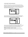
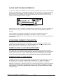
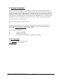
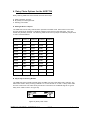
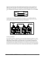
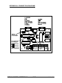
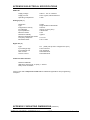
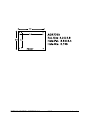
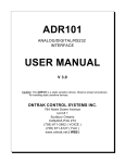
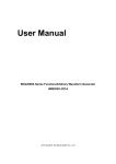
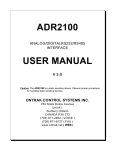
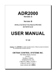
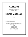
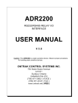
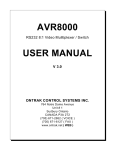
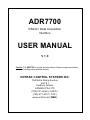
ADR7700
RS232 / Data Acquisition
Interface
USER MANUAL
V 1.0
Caution: The ADR7700 is a static sensitive device. Observe proper procedures
for handling static sensitive devices.
ONTRAK CONTROL SYSTEMS INC.
764 Notre Dame Avenue
Unit # 1
Sudbury Ontario
CANADA P3A 2T2
(705) 671-2652 ( VOICE )
(705) 671-6127 ( FAX )
www.ontrak.net ( WEB )
Ontrak Control Systems Inc. reserves the right to change product specifications to improve the
product.
Although every attempt has been made to insure accuracy of information contained in this
manual, Ontrak Control Systems Inc. assumes no liability for inadvertent errors.
W arranty: This ADR7700 is warranted from defects in workmanship and materials for a period of
90 days. Liability for defects is limited to the purchase price of the product. This warranty shall not
apply to defects resulting from improper modifications or use outside published specifications.
Hyperterminal and Windows are trademarks of Microsoft Corporation.
APPLE , MACINTOSH and MAC are trademarks of Apple Computer Inc.
PC, XT, AT, PS/2 are trademarks of International Business Machines Inc.
COPYRIGHT 1999 ONTRAK CONTROL SYSTEMS INC.
TABLE OF CONTENTS
READ ME FIRST
3
1. Communication options.
a) The ADR7700 RS232 Interface.
b) The ADR7700 RS485 Interface
2. Powering the ADR7700
3. ADR7700 Command Set
a) Analog Commands
b) Digital Commands
c) Interrupt Commands
d) ID Command
4. Daisy Chain Options for the ADR7700
5. Using Interrupt Functions
4
5
5
6
7
7
9
9
10
12
APPENDIX
A-CONNECTION DIAGRAM
B-ELECTRICAL SPECIFICATIONS
C-MOUNTING DIMENSIONS
ONTRAK CONTROL SYSTEMS INC.
2/15
14
15
16
www.ontrak.net
READ ME FIRST
Thank you for purchasing this ADR7700 Data Acquisition Interface. There are
three steps to using the ADR7700.
1.Connecting your computer or terminal to the ADR7700.
2.Providing power to the ADR7700.
3.Sending commands to the ADR7700.
This manual will provide guidance for completing these steps. Additional
applications and programming examples are available on our web page at
http://www.ontrak.net/
FEATURES
- 16-bit analog input with OEM specified input range
- High accuracy, sigma-delta core with calibration via internal 33-bit A/D
- LOW offset or gain error via internal calibration
- Two broadcast modes ( 1Hz and 10 Hz )
- Maximum sample rate of 60Hz in polling configuration
- 4 Digital I/O lines ( sink/source 20mA )
-RS232, RS485 communications
- Operates on standard 5VDC or 9-24VDC
ONTRAK CONTROL SYSTEMS INC.
3/15
www.ontrak.net
1a)THE ADR7700 RS232 INTERFACE
To operate the ADR7700 via RS232, the communications select jumper must be set to the
RS232 position. ( See Appendix A ) The only signals used are received data (RC), transmitted
data (TX) and ground (GND). Most RS232 ports use hardware handshaking (i.e. DTR, DSR, CTS,
RTS) signals to control the flow of data on the port. For this reason the cable required to connect
to the ADR7700 must have jumpers on the DB25 end to satisfy these handshaking requirements.
IBM or compatible computers may be used as a host computer with the supplied cable. The
supplied cable has the following connections;
Figure 1: Supplied Cable Wiring Diagram
If the host computer has a 9-pin serial port connector, a 9-pin to 25-pin adapter cable will be
required to connect to the ADR7700 cable. This adaptor is available at most computer dealers. If
possible, the DB25 connector on the supplied cable may be removed and a female DB9S
connector can be soldered in its place using the following wiring diagram;
Figure 2: Modified Wiring Diagram For 9-PIN SERIAL PORTS
If the host computer has a female DB25 connector, a male-to-male adapter is required to use the
supplied cable. This may be purchased at most computer dealers. Apple Macintosh computers
may be connected to the ADR7700 using MAC to DB25 DTE conversion cable.
Once connected to the RS232 based host computer or terminal, the RS232 port should be
configured to the following specifications to allow communication with the ADR7700.
9600 baud - 8 bit words - 1 stop bit - no parity
If a terminal or terminal emulation program is used, configure your terminal to the above
specifications using the operations manual for your terminal equipment or terminal emulation
program.
ONTRAK CONTROL SYSTEMS INC.
4/15
www.ontrak.net
1b)THE ADR7700 RS485 INTERFACE
To operate the ADR7700 via RS485, the Communications select jumper must be set to the RS485
position. ( See Appendix A ). The ADR7700 RS485 interface is a two-wire connection meeting all
the standards of the EIA RS485 interface specifications. To communicate via RS485 the host
computer must have an RS485 port and be connected directly with two wires ( TR+ and TR-). A
typical connection diagram is shown in figure 2.
Figure 2 : Typical RS485 Connection
Note that both J1 and J2 are RS485 compatible ports. Connection from the host to the ADR7700
should be made using J1 and then J2 is used to enable daisy chaining additional ADR7700
products.
The host RS485 port should be configured with the following specifications to enable
communications to the ADR7700, 9600 Baud - 8 bit words - 1 stop bit - no parity.
Line feeds should NOT be sent after commands as they may collide with data being returned from
the ADR7700.
2.PROVIDING POWER TO THE ADR7700
The ADR7700 may be powered using a regulated 5 volt power supply or a 9-24VDC source.
Power to daisy chained ADR7700's may also be supplied via the daisy chain cable. See the
Daisy chaining section of this manual for further information.
POWER-UP USING A 5 VOLT REGULATED SUPPLY
If the ADR7700 is to be powered using a regulated 5 volt power supply, the 5VDC and GND
connections are to be made to the ADR7700 via the main terminal block TB1. The supply must be
able to provide a minimum of 50mA. Care must be taken to avoid improper pow er supply
connection as permanent damage to the ADR7700 may result if connected improperly.
POWER-UP USING A 9-24VDC SUPPLY
The ADR7700 has an on-board 5 volt regulator allowing the use of a 9-24VDC supply to power
the internal circuits. The supply should be able to provide from 50 - 230mA. The supply is
connected to pin 6 ( +) and pin 1 ( GND ) of either J1 or J2. ( see appendix A ). When the
ADR7700 is powered by a 9-24VDC supply, the on-board regulator also may provide a regulated
5 volts DC out to provide power to external circuits. This 5 volt supply is available on TB1. For
safe operation no more than 100mA should be draw n from the pow er terminals to pow er
external circuits.
ONTRAK CONTROL SYSTEMS INC.
5/15
www.ontrak.net
ANALOG COMMAND SUMMARY
RV
BV1
BV2
CAL
Returns present value of analog input ( 00000-65535 )
Broadcasts value of analog input every 1000ms
Broadcasts value of analog input every 100ms.
Calibrates analog to digital converter
DIGITAL COMMAND SUMMARY
CPAxxxx
SPAxxxx
MAdd
SETPAx
RESPAx
RPA
RPAn
PA
Configures individual lines of PORT A as input or output
( x=1 for input, x= 0 for output )
Outputs binary data to PORT A ( x= 1 or 0 ) ( MSB-LSB )
Outputs decimal data ( dd=00 to 15 ) to PORT A
Sets I/O line specified by x ( x= 0 to 3 ) in PORT A
Resets I/O line specified by x ( x = 0 to 3 ) in PORT A
Returns status of all I/O lines in PORT A in binary format.
Returns status of I/O line specified by n. (n= 0 to 3 )
Returns status of PORT A in decimal format.
INTERRUPT COMMAND SUMMARY
IE
ID
IS
Enable Interrupts.
Disable Interrupts
Returns Interrupt Status ( 1 if enabled, 0 if disabled )
ID COMMAND
*IDN?
Returns 4 digit product identifier code. ( 7700 )
ONTRAK CONTROL SYSTEMS INC.
6/15
www.ontrak.net
3. ADR7700 COMMANDS
a) Analog Commands
There is one, 16-bit analog input on the ADR7700 with input terminals labeled V+ and V- on TB1.
The input is either configured as single-ended or differential type. When reading a single-ended
type, the ADR7700 returns a value of 00000 to 65535 where 00000 represents ZERO and 65535
represents full scale. When reading a differential type, the ADR7700 returns a value of 00000 to
65535 where 00000 represents negative full-scale, 32768 represents ZERO, and 65535
represents positive full scale. ( Differential measurements are with reference to V- )
RV
Returns present value of analog input as a decimal number from 00000 to 65535
EX1;
RV<cr>
45687
( ADR7700-SE15 )( single-ended type )
( AGND=GND, V+ = applied voltage )
Analog voltage is (45687/65535) * 15 =10.4570 Volts
EX1;
RV<cr>
10345
( ADR7700-DI5 )( differential type )
( AGND=GND, V- = Vin-, V+ = Vin+ )
Analog voltage is ( ( 10345/65535 ) *10 ) - 5 = -3.42145 Volts
NOTE: The broadcast commands ( following ) are recommended for use via RS232 only.
Broadcasting can be used on RS485, however, there is a possibility of a collision between
returned data and any character user to stop the broadcasting.
BV1
Broadcasts analog voltage reading every 1000ms.
( terminated by any received character )
BV2
Broadcasts analog voltage reading every 100ms.
( terminated by any received character )
CAL
Performs an internal calibration to eliminate end-of-scale, offset and start-of-scale
errors. This command is executed on power-up and should be executed when
there is a significant change in ambient temperature of the ADR7700.
b) Digital Commands
There is one, four bit digital port on the ADR7700 labeled PORT A. The individual I/O lines are
labeled PA0-PA3. The following commands allow the user to;
-configure individual bits an input or output
-SET or RESET individual bits
-read individual bits
-read entire port in binary or decimal format
-write to entire port in binary or decimal format.
The digital port commands are;
CPAxxxx
Configures each bit of PORT A . All four bits must be specified. Order
is MSB-LSB ( x=1 for input, x=0 for output )
ONTRAK CONTROL SYSTEMS INC.
7/15
www.ontrak.net
example;
CPA1100<CR>
( PA3 and PA2 are configured as inputs, PA1 and PA0 are configured as outputs
)
SPAxxxx
Outputs binary data to PORT A. All four bits must be specified.
Order is MSB-LSB. Individual bits configured as input are not
effected by this command. (x=1 or 0 )
example;
SPA1010<CR>
( PA3 and PA1 are set, PA2 and PA0 are reset )
RPA
Returns status of all I/O lines in PORT A in binary format. Order is MSB-LSB.
Individual lines configured as output will return last data set on the port.
example;
RPA<CR>
0111
( PA3 is low, PA2, PA1, and PA0 are high )
RPAn
Returns status of I/O line in PORT A specified by n.( n=0 to 3 )
example;
RPA3<CR>
1
( PA3 is high )
Madd
Outputs decimal data (dd) to PORT A. Individual lines configured as input are not
effected by this command. (dd= 00 to 15 )
example;
MA15<CR>
( All lines of PORT A are set )
PA
Returns status of PORT A in decimal format. Individual lines configured as
output will return last data set on PORT A.
example;
PA<CR>
04
( PA2 is high, PA3, PA1 and PA0 are low )
RESPAn
Resets I/O line specified by n in PORT A. This command has no effect on I/O
lines configured as input. ( n=0 to 3 )
example;
RESPA0<CR>
( PA0 is reset )
SETPAn
Sets I/O line specified by n in PORT A. This command has no effect on I/O
lines configured as input. ( n=0 to 3)
example;
SETPA3<CR>
( PA3 is set )
ONTRAK CONTROL SYSTEMS INC.
8/15
www.ontrak.net
c) Interrupt Commands
The ADR7700 has four digital I/O lines ( PA0,PA1,PA2,PA3 ) that can be used to provide an
interrupt to the host when pulled low . The digital I/O lines used for interrupts must be configured
as input to operate. W hen any digital I/O line is configured as input, an internal pull-up resistor is
enabled to pull the line high. When interrupts are enabled, bringing any line low will cause a two
digit value to be returned to the host. The first digit is the board address ( 0 - 9 ) and the second
identifies the source of the interrupt ( 1 for PA0, 2 for PA1, 3 for PA2, 4 for PA3). For example;
- an interrupt on PA0 on board 0 returns
01
- an event counter match on board 3 returns
35
Interrupts generated at the same instant will be returned with highest priority given to PA0,
followed by PA1,PA2, and PA3. All interrupts are disabled on power up. See the applications
section titled Using Interrupt Functions for further details.
The Interrupt commands are;
IE
ID
IS
Enables all interrupts
Disables all interrupts.
Returns status of interrupts ( 0 if disabled, 1 if enabled )
d) ID Command
*IDN?
Returns ID code ( 2200 )
* may be omitted
ONTRAK CONTROL SYSTEMS INC.
9/15
www.ontrak.net
4. Daisy Chain Options for the ADR7700
Daisy chaining ADR7700 series boards involves three steps.
A. Setting Address Jumpers
B. Physically Connecting Boards
C. Sending commands
A. Setting Address Jumpers
The ADR7700 can be daisy-chained when operated in RS485 mode. Each board on the chain
must be assigned an address via the BCD address jumper block on the ADR7700. Up to ten
boards may be daisy-chained. The following table shows how to jumper the address jumper block
to select a board address.
Position 8
Position 4
Position 2
Position 1
Address
OPEN
OPEN
OPEN
OPEN
0
OPEN
OPEN
OPEN
JUMP
1
OPEN
OPEN
JUMP
OPEN
2
OPEN
OPEN
JUMP
JUMP
3
OPEN
JUMP
OPEN
OPEN
4
OPEN
JUMP
OPEN
JUMP
5
OPEN
JUMP
JUMP
OPEN
6
OPEN
JUMP
JUMP
JUMP
7
JUMP
OPEN
OPEN
OPEN
8
JUMP
OPEN
OPEN
JUMP
9
Table 1. Address Jumper Settings.
B. Physically Connecting Boards
The ADR7700 series interface boards have two DB9 connectors that allow daisy chaining. The
data format used in daisy chaining is RS485. To connect boards on a chain, a daisy chain cable
must be constructed. The cable must provide two connections for the RS485 signals. A typical
daisy-chain cable is shown in Figure 5a)
Figure 5a) Daisy-chain cable
ONTRAK CONTROL SYSTEMS INC.
10/15
www.ontrak.net
Power may be shared in daisy-chained ADR7700 series interfaces if two extra conductors are
added to the daisy-chain cable. Care should be taken that the output current limitation on the
power supply is not exceeded. The connections for a powered daisy-chain cable are shown in
Figure 5B) NOTE: Pow er sharing is available only if pow er is applied via J1 or J2 ( 9-24VDC
).
Figure 5b) Powered Daisy-Chain Cable
The Daisy-chain cable can be connected from J2 to either J1 or J2 on additional ADR7700
interfaces. Both J1 and J2 have identical pinouts for RS485 and power signals used for daisychain applications. Figure 5c) shows a typical daisy-chain application.
Figure 5c) Typical Daisy-Chain Application
C Sending Commands
Once a board is jumpered, it will respond only to commands preceded by its address as a single
digit integer number. For example to read PA0 on board 3 the command “3RPA0"<cr> is sent. To
read the analog voltage at board 7 the command “7RV"<cr> is sent. Spaces sent between the
board address and commands are ignored. Board zero will respond to both commands with no
preceding address and commands preceded with a zero for reasons of continuity. Never connect
two boards with the same address on the same chain. This will result in both boards responding at
the same time and will cause contention on the network with possible damage to the ADR boards.
ONTRAK CONTROL SYSTEMS INC.
11/15
www.ontrak.net
5. Using Interrupt Functions
The ADR7700 has four digital input lines ( PA0,PA1,PA2,PA3 ) that can be used to provide an
interrupt to the host when an input is pulled low. All digital I/O lines configured as inputs have built
in pull-up resistors tied to the 5 volt supply. When interrupts are enabled, bringing any input line
low will return a two digit value to the host. The first digit is the board address ( 0 - 9 ) and the
second identifies the source of the interrupt ( 1 for PA0, 2 for PA1, 3 for PA2, 4 for PA3 )
For example;
- an interrupt on PA0 on board 0 returns
01
- an interrupt on PA2 on board 5 returns
53
Interrupts generated at the same instant will be returned with highest priority given to PA0,
followed by PA1,PA2, and PA3. All interrupts are disabled on power up.
The Interrupt commands are;
IE
ID
IS
Enables all interrupts
Disables all interrupts.
Returns status of interrupts ( 0 if disabled, 1 if enabled )
Notes To Operation.
1.
The IS ( interrupt status ) command should be used following an ID ( interrupt disable )
command to verify interrupts have been disabled. This may be required in cases where
there is a possibility of an interrupt being generated when the ID command is issued. The
primary communication used by ADR7700 series interfaces is Half-Duplex RS485 and
interrupt data may collide with the ID command resulting in the ID command not being
received by the ADR7700.
2.
Once an interrupt is generated and data is sent to the host, no further interrupts will be
generated by that particular input unless the IE command is sent. W hen interrupt data is
sent to the host, that input is masked and the issuing the command IE is the only method
to un-mask the input.
ONTRAK CONTROL SYSTEMS INC.
12/15
www.ontrak.net
.APPENDIX
A CONNECTION DIAGRAM
ONTRAK CONTROL SYSTEMS INC.
13/15
www.ontrak.net
APPENDIX B ELECTRICAL SPECIFICATIONS
ADR7700
Supply Voltage
Supply Current
Operating Temperature
5VDC+/- 10% or 9-24VDC
40mA Typical, 50mA Maximum
0-50C
Analog Input ( 1 )
Resolution
Type
Integral Non-Linearity
Input Ranges
Input Impedance
Maximum Noise
Reference Stability
Maximum Sample Rate 60Hz
Frequency Response
Broadcast Rates
16-bits
Single-Ended or Differential
0.0015%
Various ( Factory Set )
10Kohm Min.
10uV
7ppm/C
15.72 Hz
1Hz or 10Hz
Digital I/O ( 4 )
Type
Input Voltage High
Input Voltage Low
Sink Current
Source Current
TTL ( weak pull-up when configured as input )
4.00V minimum
0.8V maximum
20mA Maximum
20mA Maximum
Communication Interface
RS232 and RS485
9600 baud, 8 bit words, no parity, 1 start bit
Daisy-chain via RS485
Visit our web site at http://w w w .ontrak.net/ for additional applications and programming
examples.
APPENDIX C MOUNTING DIMENSIONS ( INCHES )
ONTRAK CONTROL SYSTEMS INC.
14/15
www.ontrak.net
ONTRAK CONTROL SYSTEMS INC.
15/15
www.ontrak.net