1
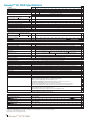
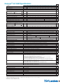
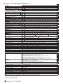
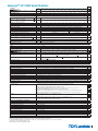
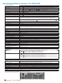
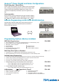
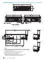
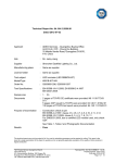
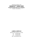
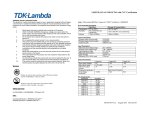
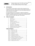
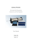
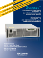
The GenesysTM family of programmable power supplies sets a new standard for flexible, reliable, AC/DC
power systems in OEM, Industrial and Laboratory applications.
Features include:
•
•
•
•
•
•
•
•
•
•
•
•
•
•
High Power Density 10kW/15kW in 3U package
High Output Current up to 1000ADC
Wide Range of popular worldwide 3Ф AC inputs, (208VAC, 400VAC, 480VAC)
Power Factor 0.88 (Passive PFC on all AC Inputs)
Output Voltage up to 1500V; Output Current up to 1000A
Built-in RS-232/RS-485 Interface Standard
Last Setting Memory; Front Panel Lockout
“Advanced Parallel” configuration reports total system current (up to four identical units)
Global Commands for Serial RS-232/RS-485 Interface
Continuous Encoders for Voltage and Current Adjustment
Independent Remote ON/OFF and Remote ENABLE/DISABLE
Reliable Modular and SMT Design
19” Rack Mounted for ATE and OEM Applications, zero-stack
Optional Interfaces
Compliant LAN (Class C)
GPIB (IEEE 488.2 & SCPI Compliant) w/ Multi-Drop capability
Isolated Analog Programming and Monitoring Interface (0-5V/0-10V & 4-20mA)
•
•
LabViewTM and LabWindowsTM Software Drivers
Worldwide Safety Agency Approvals; UL Recognized and CE Mark for LVD
and EMC Regulation (208VAC, 400VAC and select 480VAC models)
Five Year Warranty
•
Applications
Genesys™ power supplies are designed for demanding applications.
Test & Measurement systems using GPIB control save significant costs by incorporating the optional IEEE MultiDrop Interface (IEMD) in the Master unit. Then up to 30 Slave units may be used with the standard RS-485 Multi-Dropinterface.
Automated System designers will appreciate new, standard, remote programming features such as Global
commands. Also, new high-speed status monitoring is available for the RS-485 bus as well as the optional LAN
(LXI compliant) Interface.
Industrial & Military high power systems can be configured with up to four identical units in parallel (up to 60kW).
No space is required above or below each power supply (zero stack). The Master unit can be configured by the user to
report the total Output current of the combined system. Applications include Heaters, Magnets and Laser Diodes.
Aerospace & Satellite Testing systems use the complete Genesys™ Family: 1U-750W Half-Rack, 1U-750W/
1.5kW/2.4kW Full-Rack, 2U-3.3kW/5kW Full-Rack and 3U-10kW/15kW Full-Rack. All are identical in Front Panel, Rear
Panel Analog and Digital Interface Commands. A wide variety of Outputs (voltage and current) allows testing of many
different user configurations.
Component Device Testing is simplified because of the many user-friendly control options in the Analog and
Digital interfaces. Lamps, capacitors, motors and actuators are typical devices tested.
Medical Imaging and Treatment systems require reliable power. Modular construction, SMT and thoroughly
proven designs assure continuous performance at full rated power.
Semiconductor Processing & Burn-in equipment designers appreciate the wide variety of worldwide AC
Inputs and Outputs from which to select, depending on application. Selectable Safe-Start and Auto Re-Start protects
loads and process integrity. Typical applications include Magnets, Filaments and Heaters.
1 GenesysTM 3U 10/15kW
Front Panel Description
4
1
6
3
5
7
8
2
1.
2.
3.
4.
5.
6.
7.
AC ON/OFF Switch
Air Intake allows zero stacking for maximum system flexibility and power density.
Continuous encoder controls Output Voltage, Address, OVP and UVL settings.
Voltage Display shows Output Voltage and directly displays OVP, UVL and Address settings.
Continuous encoder controls Output Current, sets Baud rate and Advanced Parallel mode.
Current Display shows Output Current and displays Baud rate. Displays total current in Parallel Master/Slave Mode.
Function/Status LEDs:
• Alarm
• Fine Control
• Preview Settings
• Foldback Mode
• Remote Mode
• Output On
8. Pushbuttons allow flexible user configuration
• Coarse and Fine adjustment of Output Voltage/Output Current and Advanced Parallel Master or Slave select.
• Preview Settings and set Voltage/Current with Output OFF, Front Panel Lock.
• Parallel Master/Slave (Basic and Advanced).
• Set OVP and UVL Limits.
• Set Current Foldback Protection.
• Go to Local Mode and select Address and Baud rate.
• Output ON/OFF and Safe-Start/Auto Re-Start mode.
Rear Panel Description
1
2
4
3
5
9
7
6
8
1.
2.
3.
4.
5.
6.
Remote/Local Output Voltage Sense Connections.
DIP Switches select 0-5V or 0-10V Programming and other functions.
DB25 (Female) connector allows Analog Program and Monitor (non-isolated) and other functions.
RS-485 OUT to other Genesys™ Power Supplies.
RS-232/RS-485 IN Remote Serial Programming.
Output Connectors: Rugged 2 hole busbars (shown) for models < 30V Output,
single hole busbars for 30V to 300V Output, and threaded-stud terminals for models > 300V Output.
7. Exit air assures reliable operation when zero stacked.
8. Input Terminals L1, L2, L3, and Ground (threaded studs).
9. Optional Interface Position for LAN (LXI Class C), GPIB (IEEE 488.2 SCPI) or Isolated Analog Interface.
LAN Interface complies with
Class C Specification
2
GenesysTM 3U 10kW Specifications
1.0 MODEL
1.Rated Output Voltage
2.Rated Output Current
3.Rated Output Power
4.Efficiency (min) at low AC line, 100% Rated Load
GEN
VDC
ADC
kW
%
7.5-1000 10-1000 12.5-800 20-500 25-400 30-333 40-250 50-200 60-167
7.5
10
12.5
20
25
30
40
50
60
1000
1000
800
500
400
333
250
200
167
0.75
10.0
10.0
10.0
10.0
10.0
10.0
10.0
10.0
77
83
Contact Factory for other models
80-125
80
125
10.0
100-100
100
100
10.0
125-80
125
80
10.0
10kW
X
X
X
X
X
X
1.1 CONSTANT VOLTAGE MODE (CV)
1. Max. Line Reg (0.1% - Vor ≤ 30V; 0.01% - 30V < Vor <
600V; 0.05% - 600V < Vor < 1500V)
2. Max. Load Reg (0.1% - Vor ≤ 30V; 0.02% - 30V < Vor <
600V; 0.1% - 600V < Vor < 1500V)
3. Ripple, rms, 5Hz~1MHz, CV (*1)
4. Output Noise, p-p, (20MHz), CV (*1)
5.Remote Sense Compensation / Wire
6. Temperature Stability
7. Temperature Coefficient
8. Up-Prog. Response Time, 0 ~ Vomax, full-load
9. Up-Prog. Response Time, 0~Vomax, no-load
10. Transient Response Time (CV mode) (*2)
mV
7.5
10
12.5
20
25
30
4
5
6
8
10
12.5
X
mV
7.5
10
12.5
20
25
30
8
10
12
16
mV
mV
V
--ppm / °C
ms
ms
ms
20
25
X
20
20
20
20
20
20
20
20
20
25
25
60
60
60
60
60
60
60
75
75
100
100
1
1
1
1
1
1.5
2
3
3
4
5
± 0.05% of Vo(rated) over 8 hours after 30 minute warm up (constant Line, Load & Temperature)
± 200 (± 0.02% of Vo Rated) / °C
100
50
Less than 3
25
125
5
X
X
X
X
X
X
X
X
1000
1000
800
500
400
333
125
100
83.5
62.5
50
40
X
1000
1000
800
500
400
333
188
150
125
94
75
60
X
5300
4000
2560
1000
640
444
250
160
67
50
40
± 0.05% of Io(rated) over 8 hours after 30 minute warm up (constant Line, Load & Temperature)
± 300 (± 0.03% of Io Rated) / °C
32
X
X
X
1.2 CONSTANT CURRENT MODE (CC)
1. Max. Line Reg. (0.1% - Ior > 333A; 0.050% - 17A < Ior <
333A; 0.15% - Ior < 17A)
2. Max. Load Reg (0.1% - Ior > 333A; 0.075% - 17A < Ior <
333A; 0.2% - Ior < 17A) (*3)
3. Ripple rms, 5Hz~1MHz, CC
4. Temperature Stability
5. Temperature Coefficient
1.3 PROTECTIVE FUNCTIONS
1. OCP
2. OCP type
3. Foldback Protection (FOLD)
4. Foldback Response Time
5. OVP type
6. OVP Programming Accuracy
7. OVP Trip Point
mA
mA
mA
--ppm/°C
%
----S
--%
V
8. OVP Response Time
ms
9. Max. OVP Reset Time
10. Over-Temperature Protection (OTP)
11. Phase-Loss Protection
1.4 REMOTE ANALOG CONTROLS & SIGNALS
1. Vout Voltage Programming
2. Iout Voltage Programming
3. Vout Resistor Programming
4. Iout Resistor Programming
5. Shut-Off (SO) Control (rear panel)
6. Output Current Monitor
7. Output Voltage Monitor
8. Power Supply OK (PS_OK) Signal
9. CV/CC Signal
10. Enable/Disable
11. Remote/Local Selection
12. Remote/Local Signal
1.5 FRONT PANEL
1.Control Functions
2.Display
3.Indications
1.6 DIGITAL PROGRAMMING & READBACK
1. Vout Programming Accuracy
2. Iout Programming Accuracy
3. Vout Programming Resolution
4. Iout Programming Resolution
5. Vout Readback Accuracy
6. Iout Readback Accuracy
7. Vout Readback Resolution
8. Iout Readback Resolution
9. OV Response Time
10. Other Functions
s
-----
0 ~ 100
Constant current
Output shutdown; Manual reset by front panel OUT button or Digital communication, user-selectable
Less than 1 (Min = 0.25 / Max = 25 / Default = 0.25); Settable via “FBD” command
Inverter shut-down; Manual reset by AC On/Off recycle, OUT button, Remote Analog or Digital commuincation
± 5% of Vo(rated)
5% to 105% of Vo(rated) - for Vor < 600V; 10% to 105% of Vo(rated) - 600V < Vor < 1500V; Shall always be greater
than 105% of Vo(setting); Default = 105% of Vo(rated).
Less than 10 (for Output to begin to drop) for Vor < 600V; Less than 2.0 (for Output to begin to drop) for
600V < Vor < 1500V.
7 (from AC On/Off switch turn On)
Shut down if internal temperature exceeds safe operating levels (Latched: Safe-mode / Unlatched: Auto-mode)
Yes, power supply shutdown (Latched: Safe-mode / Unlatched: Auto-mode)
X
X
X
X
X
0~100%, 0 ~ 5V or 0 ~ 10V, user-selectable., Accuracy & Linearity: ±1% of Vo(rated)
0~100%, 0 ~ 5V or 0 ~ 10V, user-selectable, Accuracy & Linearity: ± 1% of Io(rated)
0~100%, 0 ~ 5/10kohm full-scale, user-selectable, Accuracy & Linearity: ± 1% of Vo(rated)
0~100%, 0 ~ 5/10kohm full-scale, user-selectable, Accuracy & Linearity: ± 1% of Io(rated)
By Voltage: 0.6V = Disable, 2-15V = Enable (default) or Dry Contact: Open = EN, Short = DIS (user-selectable logic)
0 ~ 5V or 0 ~ 10V, Accuracy: ± 1% of Io(rated), user-selectable
0 ~ 5V or 0 ~ 10V, Accuracy: ± 1% of Vo(rated), user-selectable
Yes. TTL High = OK, 0V = Fail (500ohm series impedance)
CV: TTL High (4 ~ 5V), Max source current = 10mA; CC: TTL Low (0 ~ 0.4V), Max sink current = 10mA
Dry contact; Open = Off, Short = On; Max. voltage across Enable/Disable contacts = 6V
Selects Remote or Local operation by voltage: 0 ~ 0.6V = Local / 2 ~ 15V = Remote
Signals operating mode; Open collector: Local = Open (Max voltage = 30V), Remote = On (Max sink current = 10mA)
X
X
X
X
X
X
X
X
X
X
X
X
Vout/ Iout manual adjust by separate encoders (coarse and fine adjustment selectable)
OVP/UVL manual adjust by Voltage Adjust encoder, Front Panel Lock/Unlock
Address selection by Voltage Adjust encoder. # of addresses = 31
AC ON/OFF, Output On/Off, Restart Modes (Auto/Safe), Foldback Control (CV to CC), Go-to-Local
RS-232/RS-485, IEEE (IEMD) and LAN selection by rear panel DIP-switch
Baud rate selection (RS-232/RS-485 only): 1200, 2400, 4800, 9600 and 19,200 (by current adjust encoder)
Advanced Parallel Master/Slave: Hx = Master unit, where x = # of Slave units (0 to 4), S = Slave unit(s)
Voltage: 4 digits, Accuracy: ± 0.5% of Vo(rated) ±1 count
Current: 4 digits, Accuracy: ± 0.5% of Io(rated) ±1 count
Voltmeter displays voltage at power supply (Local sense) or at load (Remote sense)
Green LED’s: PREVIEW, FOLD, REM/LOCAL, OUT ON/OFF, CV/CC, FINE
Red LED: ALRM (OVP, OTP, FOLD, AC FAIL, ENA, SO)
X
X
X
X
X
X
X
X
X
X
± 0.5% of rated Output voltage
± 0.5% of rated Output current for units with Io < 187.5A; ± 0.7% of rated Output current for Io ≥187.5A
0.02% of Vo(rated)
0.04% of Io(rated)
± (0.1% of Vo(actual) + 0.2% of Vo(rated))
± (0.1% of Io(actual) + 0.4% of Io(rated))
0.02% of Vo(rated)
0.02% of Io(rated)
20ms maximum (between Vout exceeding IEEE Limit and supply Inhibit turning On)
Set OVP/UVL limits; Set Local/Remote, Operating parameters and Status, Get Identity
*1. Ripple and Noise at Vo(rated) and rated Load, Ta = 25C and nominal AC input, per EIJ R9002A.
*2. Time for the Output voltage to recover within 2% of rating for a load current change of 50~100% or 100-50% of Io(rated).
*3 .From 20% - 100% for models with Ior < 17A.
All specifications subject to change without notice.
3 GenesysTM 3U 10/15kW
X
X
X
X
X
X
X
X
X
X
X
X
X
X
X
X
X
GenesysTM 3U 10kW Specifications
1.0 MODEL
1250*
1500*
X
8.0
6.7
X
10.0
10.0
X
X
X
500
625
750
X
1000
1250
1500
X
140
1400
5
X
X
X
X
X
X
X
X
1.Rated Output Voltage
VDC
150
200
250
300
400
500
600
800*
1000*
2.Rated Output Current
ADC
66
50
40
33
25
20
17
12.5
10
kW
%
9.9
10.0
10.0
10.0
10.0
mV
15
20
25
30
40
50
60
400
mV
30
40
50
60
80
100
120
800
1.1 CONSTANT VOLTAGE MODE (CV)
1. Max. Line Reg (0.1% - Vor ≤ 30V; 0.01% - 30V < Vor <
600V; 0.05% - 600V < Vor < 1500V)
2. Max. Load Reg (0.1% - Vor ≤ 30V; 0.02% - 30V < Vor <
600V; 0.1% - 600V < Vor < 1500V)
3. Ripple, r.m.s, 5Hz~1MHz, CV (*1)
4. Output Noise, p-p (20MHz), CV (*1)
5.Remote Sense Compensation / Wire
6. Temperature Stability
7. Temperature Coefficient
8. Up-Prog. Response Time, 0~Vomax, full-load
9. Up-Prog. Response Time, 0~Vomax, no load
10. Transient Response Time (CV mode) (*2)
1.2 CONSTANT CURRENT MODE (CC)
1. Max. Line Reg. (0.1% - Ior > 333A; 0.050% - 17A < Ior <
333A; 0.15% - Ior < 17A)
2. Max. Load Reg (0.1% - Ior > 333A; 0.075% - 17A < Ior <
333A; 0.2% - Ior < 17A) (*3)
3. Ripple rms, 5Hz~1MHz, CC
4. Temperature Stability
5. Temperature Coefficient
mV
mV
V
--ppm / °C
mS
mS
mS
17
13
10
9
19
15
12
10
X
mA
50
38
30
25
19
15
13
25
20
15
14
X
4
X
X
X
mA
--ppm / °C
8. OVP response time
mS
9. Max. OVP reset time
10. Over-Temperature Protection (OTP)
S
-----
3.Indications
1.6 DIGITAL PROGRAMMING & READBACK
1. Vout Programming Accuracy
2. Iout Programming Accuracy
3. Vout Programming Resolution
4. Iout Programming Resolution
5. Vout Readback Accuracy
6. Iout Readback Accuracy
7. Vout Readback Resolution
8. Iout Readback Resolution
9. OV Response Time
10. Other Functions
25
35
35
60
60
60
60
80
100
120
150
175
200
200
300
350
350
700
800
1000
5
5
5
5
5
5
5
5
5
5
± 0.05% of Vo(rated) over 8 hours after 30 minute warm up (constant Line, Load & Temperature)
± 200 (0.02% of Vo Rated) / °C
100
17
50
17
Less than 3
Less than 1
20
V
2.Display
93.5
25
7. OVP Trip Point
1.5 FRONT PANEL
1.Control Functions
9.9
10.0
10.0
10.2
83
Contact Factory for other models
1250-8
33
%
----S
--%
1.4 REMOTE ANALOG CONTROLS & SIGNALS
1. Vout Voltage Programming
2. Iout Voltage Programming
3. Vout resistor programming
4. Iout Resistor Programming
5. Shut-Off (SO) Control (rear panel)
6. Output Current Monitor
7. Output Voltage Monitor
8. Power Supply OK (PS_OK) Signal
9. CV/CC Signal
10. Enable/Disable
11. Remote/Local Selection
12. Remote/Local Signal
500-20 600-17 800-12.5 1000-10
mA
1.3 PROTECTIVE FUNCTIONS
1. OCP
2. OCP type
3. Foldback Protection (FOLD)
4. Foldback Response Time
5. OVP type
6. OVP Programming Accuracy
11. Phase-Loss Protection
400-25
10kW
X
150-66
3.Rated Output Power
4.Efficiency (min) at low AC line, 100% Rated Load
200-50 250-40 300-33
1500-6.7
GEN
26
20
16
13
10
8
7
15
10
6
± 0.05% of Io Rated over 8 hours after 30 minute warm up (constant Line, Load & Temperature)
± 300 (0.03% of Io Rated) / °C
0 ~ 100
X
Constant current
X
Output shut down; Manual reset by front panel OUT button or Digital communication, user-selectable
X
Less than 1 (Min = 0.25 / Max = 25 / Default = 0.25); Settable via “FBD” command
X
Inverter shut-down; Manual reset by AC On/Off recycle, OUT button, Remote Analog or Digital comm.
X
± 5% of Vo(rated)
X
5% to 105% of Vo(rated) - for Vor < 600V; 10% to 105% of Vo(rated) - 600V < Vor < 1500V; Shall always be greater
than 105% of Vo(setting); Default = 105% of Vo(rated).
Less than 10 (for Output to begin to drop) for Vor < 600V; Less than 2.0 (for Output to begin to drop) for
X
600V < Vor < 1500V.
7 (from AC On/Off switch turn On)
Shut down if internal temperature exceeds safe operating levels. (Latched: Safe / Unlatched: Auto)
Yes, power supply shutdown (Latched: Safe-mode / Unlatched: Auto-mode)
X
X
X
0~100%, 0 ~ 5V or 0 ~ 10V, user-selectable, Accuracy & Linearity: ± 1% of Vo(rated)
0 ~ 100%, 0~5V or 0 ~ 10V, user-selectable. Accuracy & Linearity ± 1% of Io(rated)
0~100%, 0~5/10kohm full-scale, user-selectable. Accuracy & Linearity ± 1% of Vo(rated)
0~100%, 0~5/10kohm full-scale, user-selectable. Accuracy & Linearity ± 1% of Io(rated)
By Voltage: 0.6V = Disable, 2-15V = Enable (default) or Dry Contact : Open = ENA, Short = DIS (user-selectable logic)
0 ~ 5V or 0 ~ 10V, Accuracy: ± 1% of Io(rated), user-selectable
0 ~ 5V or 0 ~ 10V, Accuracy: ± 1% of Vo(rated), user-selectable
Yes. TTL high = OK, 0V = Fail (500ohm series impedance)
CV: TTL High (4 ~ 5V), Max source current = 10mA; CC: TTL Low (0 ~ 0.4V), Max sink current = 10mA
Dry contact; Open = Off, Short = On; Max. voltage across Enable/Disable contacts = 6V
Selects Remote or Local operation by voltage: 0 ~ 0.6V = Local / 2 ~ 15V = Remote
Signals operating mode; Open collector: Local = Open (Max voltage = 30V), Remote = On (Max sink current = 10mA)
X
X
X
X
X
X
X
X
X
X
X
X
Vout/ Iout manual adjust by separate encoders (coarse and fine adjustment selectable)
OVP/UVL manual adjust by Voltage Adjust encoder, Front Panel Lock/Unlock
Address selection by Voltage Adjust encoder. # of addresses = 31
AC ON/OFF, Output On/Off, Restart Modes (Auto/Safe), Foldback Control (CV to CC), Go-to-Local
RS-232/RS-485, IEEE (IEMD) and LAN selection by rear-panel DIP-switch
Baud rate selection (RS-232/RS-485 only): 1200, 2400, 4800, 9600 and 19,200 (by current adjust encoder)
Advanced Parallel Master/Slave: Hx = Master unit, where x = # of Slave units (0 to 4), Slave = Slave unit(s)
Voltage: 4 digits, Accuracy: ± 0.5% of Vo(rated) ±1 count
Current: 4 digits, Accuracy: ± 0.5% of Io(rated) ±1 count
Voltmeter displays voltage at power supply (Local sense) or at load (Remote sense)
Green LED’s: PREVIEW, FOLD, REM/LOCAL, OUT ON/OFF, CV/CC, FINE
Red LED: ALRM (OVP, OTP, FOLD, AC FAIL, ENA, SO)
X
X
X
X
X
X
X
X
X
X
± 0.5% of rated Output voltage
± 0.5% of rated Output current for units with Io < 187.5A; ± 0.7% of rated Output current for Io ≥187.5A
0.02% of Vo(rated)
0.04% of Io(rated)
± (0.1% of Vo(actual) + 0.2% of Vo(rated))
± (0.1% of Vo(actual) + 0.4% of Vo(rated))
0.02% of Vo(rated)
0.02% of Io(rated)
20mS maximum (between Vout exceeding IEEE Limit and supply Inhibit turning On)
Set OVP/UVL limits; Set Local/Remote, Operating Parameters and Status; Get Identity
X
X
X
X
X
X
X
X
X
X
X
*800V - 1500V models (10kW) only available with 400VA and 480VAC input. For 208VAC Input models please contact the factory.
*1. Ripple and Noise at Vo(rated) and rated Load, Ta = 25C and nominal AC input. per EIJ R9002A
*2. Time for the Output voltage to recover within 2% of rating for a load current change of 50~100% or 100~50% of Io(rated).
*3. From 20% - 100% for models with Ior < 17A.
All specifications subject to change without notice.
4
GenesysTM 3U 15kW Specifications
1.0 MODEL
1.Rated Output Voltage
2.Rated Output Current
3.Rated Output Power
4.Efficiency (min) at low AC line, 100% Rated Load
1.1 CONSTANT VOLTAGE MODE (CV)
1. Max. Line Reg (0.1% - Vor ≤ 30V; 0.01% - 30V < Vor <
600V; 0.05% - 600V < Vor < 1500V)
2. Max. Load Reg (0.1% - Vor ≤ 30V; 0.02% - 30V < Vor <
600V; 0.1% - 600V < Vor < 1500V)
3. Ripple, rms, 5Hz~1MHz, CV (*1)
4. Output Noise, p-p, (20MHz), CV (*1)
5.Remote Sense Compensation / Wire
6. Temperature Stability
7. Temperature Coefficient
8. Up-Prog. Response Time, 0 ~ Vomax, full-load
9. Up-Prog. Response Time, 0~Vomax, no load
10. Transient Response Time (CV mode) (*2)
1.2 CONSTANT CURRENT MODE (CC)
1. Max. Line Reg. (0.1% - Ior ≥ 333A; 0.050% - Ior < 333A)
2. Max. Load Reg (0.1% - Ior ≥ 333A; 0.075% - 25A < Ior <
333A; 0.2% - Ior < 25A) (*3)
3. Ripple, rms, 5Hz~1MHz, CC
4. Temperature Stability
5. Temperature Coefficient
N/A
---------
N/A
---------
N/A
---------
N/A
---------
mV
---
---
---
---
---
30
4
5
6
8
10
12.5
X
mV
---
---
---
---
---
30
8
10
12
16
20
25
X
----------20
20
20
20
25
25
----------60
60
75
75
100
100
----------1.5
2
3
3
4
5
± 0.05% of Vo(rated) over 8 hours after 30 minute warm up (constant Line, Load & Temperature)
± 200 (± 0.02% of Vo(rated)) / °C
100
50
Less than 3
25
125
5
X
X
X
X
X
X
X
X
mV
mV
V
--ppm / °C
ms
ms
ms
mA
---
---
---
---
---
500
375
334
125
94
75
60
X
---
---
---
---
---
500
375
334
188
141
113
90
X
----------350
200
150
100
100
100
± 0.05% of Io(rated) over 8 hours after 30 minute warm up (constant Line, Load & Temperature)
± 300 (± 0.03% of Io(rated)) / °C
50
X
X
X
mA
--ppm/°C
%
----s
--%
7. OVP Trip Point
V
8. OVP Response Time
ms
9. Max. OVP Reset Time
10. Over-temperature Protection (OTP)
s
-----
1.4 REMOTE ANALOG CONTROLS & SIGNALS
1. Vout Voltage Programming
2. Iout Voltage Programming
3. Vout Resistor Programming
4. Iout Resistor Programming
5. Shut-Off (SO) Control (rear panel)
6. Output Current Monitor
7. Output Voltage Monitor
8. Power Supply OK (PS_OK) Signal
9. CV/CC Signal
10. Enable/Disable
11. Remote/Local Selection
12. Remote/Local Signal
1.5 FRONT PANEL
1.Control Functions
2.Display
3.Indications
1.6 DIGITAL PROGRAMMING & READBACK
1. Vout Programming Accuracy
2. Iout Programming Accuracy
3. Vout Programming Resolution
4. Iout Programming Resolution
5. Vout Readback Accuracy
6. Iout Readback Accuracy
7. Vout Readback Resolution
8. Iout Readback Resolution
9. OV Response Time
10. Other Functions
0 ~ 100
Constant current
Output shutdown; Manual reset by front panel OUT button or DIgital communication, user-selectable
Less than 1 (Min = 0.25 / Max = 25 / Default = 0.25); Settable via “FBD” command
Inverter shut-down; Manual reset by AC On/Off recycle, OUT button, Remote Analog or Digital communication
± 5% of Vo(rated)
5% to to 105% of Vo(rated) - for Vor < 600V; 10% to 105% of Vo(rated) - 600V < Vor < 1500V; Shall always be
greater than 105% of Vo(setting); Default = 105% of Vo(rated)
Less than 10 (for Output to begin to drop) for Vor < 600V; Less than 2.0 (for Output to begin to drop) for
600V < Vor < 1500V
7 (from AC On/Off switch turn On)
Shut down if internal temperature exceeds safe operating levels (Latched: Safe-mode/ Unlatched: Auto-mode)
Yes, power supply shutdown (Latched: Safe-mode / Unlatched: Auto-mode)
X
X
X
X
X
X
X
X
X
X
X
0~100%, 0 ~ 5V or 0 ~ 10V, user-selectable., Accuracy & Linearity: ±1% of Vo(rated)
0~100%, 0 ~ 5V or 0 ~ 10V, user-selectable, Accuracy & Linearity: ± 1% of Io(rated)
0~100%, 0 ~ 5/10kohm full-scale, user-selectable, Accuracy & Linearity: ± 1% of Vo(rated)
0~100%, 0 ~ 5/10kohm full-scale, user-selectable, Accuracy & Linearity: ± 1% of Io(rated)
By Voltage: 0.6V = Disable, 2-15V = Enable (default) or Dry Contact: Open = EN, Short = DIS (user-selectable logic)
0 ~ 5V or 0 ~ 10V, Accuracy: ± 1% of Io(rated), user-selectable
0 ~ 5V or 0 ~ 10V, Accuracy: ± 1% of Vo(rated), user-selectable
Yes. TTL High = OK, 0V = Fail (500ohm series impedance)
CV: TTL High (4 ~ 5V), Max source current = 10mA; CC: TTL Low (0 ~ 0.4V), Max sink current = 10mA
Dry contact; Open = Off, Short = On; Max. voltage across Enable/Disable contacts = 6V
Selects Remote or Local operation by voltage: 0 ~ 0.6V = Local / 2 - 15V = Remote
Signals operating mode; Open collector: Local = Open (Max voltage = 30V), Remote = On (Max sink current = 10mA)
X
X
X
X
X
X
X
X
X
X
X
X
Vout/ Iout manual adjust by separate encoders (coarse and fine adjustment selectable)
OVP/UVL manual adjust by Voltage Adjust encoder, Front Panel Lock/Unlock
Address selection by Voltage Adjust encoder. # of addresses = 31
AC ON/OFF, Output On/Off, Restart Modes (Auto/Safe), Foldback Control (CV to CC), Go-to-Local
RS-232/RS-485, IEEE (IEMD) and LAN selection by rear panel DIP-switch
Baud rate selection (RS-232/RS-485 only): 1200, 2400, 4800, 9600 and 19,200 (by current adjust encoder)
Advanced Parallel Master/Slave: Hx = Master unit, where x = # of Slave units (0 to 4); S = Slave unit(s)
Voltage: 4 digits, Accuracy: ± 0.5% of Vo(rated) ±1 count
Current: 4 digits, Accuracy: ± 0.5% of Vo(rated) ±1 count
Voltmeter displays voltage at power supply (Local sense) or at load (Remote sense)
Green LED’s: PREVIEW, FOLD, REM./LOCAL, OUT ON/OFF, CV/CC, FINE
Red LED:.ALRM (OVP, OTP, FOLD, AC FAIL, ENA, SO)
X
X
X
X
X
X
X
X
X
X
± 0.5% of rated Output voltage
± 0.5% of rated Output current for units with Io < 187.5A; ± 0.7% of rated Output current for Io ≥187.5A
0.02% of Vo(rated)
0.04% of Io(rated)
± (0.1% of Vo(actual) + 0.2% of Vo(rated))
± (0.1% of Io(actual) + 0.4% of Io(rated))
0.02% of Vo(rated)
0.02% of Io(rated)
20mS maximum (between Vout exceeding IEEE Limit and supply Inhibit turning On)
Set OVP/UVL limits, Set Local/Remote, Operating parameters and Status, Get Identity
X
X
X
X
X
X
X
X
X
X
*30V, 40V and 50V models (15kW) only available with 400VAC and 480VAC. For 208VAC Input models please contact the factory.
*1. Ripple and Noise at Vo(rated) and rated Load, Ta = 25C and nominal AC input, per EIJ R9002A.
*2. Time for the Output voltage to recover within 2% of rating for a load current change of 50~100% or 100-50% of rated Output.
*3. From 20% - 100% for models with Ior < 25A.
All specifications subject to change without notice.
5 GenesysTM 3U 10/15kW
125-120
125
120
15.0
mA
1.3 PROTECTIVE FUNCTIONS
1. OCP
2. OCP type
3. Foldback Protection (FOLD)
4. Foldback Response Time
5. OVP type
6. OVP Programming Accuracy
11. Phase-Loss Protection
N/A
30-500 40-375 50-300 60-250 80-187.5 100-150
--30*
40*
50*
60
80
100
--500
375
300
250
187.5
150
--15.0
15.0
15.0
15.0
15.0
15.0
--88
Contact Factory for other models
15kW
X
X
X
X
X
X
GEN
VDC
ADC
kW
%
X
GenesysTM 3U 15kW Specifications
1500-10
15kW
X
1250*
1500*
X
12
10
X
15.0
15.0
X
X
X
500
625
750
X
1000
1250
1500
X
140
1400
5
X
X
X
X
X
X
X
X
1.0 MODEL
GEN
1.Rated Output Voltage
VDC
150
200
250
300
400
500
600
800*
1000*
2.Rated Output Current
ADC
100
75
60
50
37.5
30
25
18.8
15
kW
%
15.0
15.0
15.0
15.04
15.0
mV
15
20
25
30
40
50
60
400
mV
30
40
50
60
80
100
120
800
3.Rated Output Power
4.Efficiency (min) at low AC line, 100% Rated Load
1.1 CONSTANT VOLTAGE MODE (CV)
1. Max. Line Reg (0.1% - Vor ≤ 30V; 0.01% - 30V < Vor <
600V; 0.05% - 600V < Vor < 1500V)
2. Max. Load Reg (0.1% - Vor ≤ 30V; 0.02% - 30V < Vor <
600V; 0.1% - 600V < Vor < 1500V)
3. Ripple r.m.s, 5Hz~1MHz, CV (*1)
4. Output Noise p-p (20MHz), CV (*1)
5.Remote Sense Compensation / Wire
6. Temperature Stability
7. Temperature Coefficient
8. Up-Prog. Response Time, 0~Vomax, full-load
9. Up-Prog. Response Time, 0~Vomax, no load
10. Transient Response Time (CV mode) (*2)
1.2 CONSTANT CURRENT MODE (CC)
1. Max. Line Reg (0.1% - Ior ≥ 333A; 0.050% - Ior < 333A)
2. Max. Load Reg (0.1% - Ior ≥ 333A; 0.075% - 25A < Ior <
333A; 0.2% - Ior < 25A) (*3)
3. Ripple r.m.s, 5Hz~1MHz, CC
4. Temperature Stability
5. Temperature Coefficient
mV
mV
V
--ppm / °C
mS
mS
mS
150-100 200-75 250-60 300-50 400-37.5 500-30 600-25 800-18.8 1000-15
15.0
15.0
15.0
15.0
88
Contact Factory for other models
1250-12
93.5
25
35
35
60
60
60
60
80
100
120
150
175
200
200
300
350
350
700
800
1000
5
5
5
5
5
5
5
5
5
5
± 0.05% of Vo Rated over 8 hours, after 30 minute warm up, constant Line, Load & Temperature
200 (0.02% of Vo Rated) / °C
100
17
50
17
Less than 3
Less than 1
mA
50
38
30
25
19
15
13
28
23
18
15
X
mA
75
57
45
38
28
23
19
38
30
24
20
X
4
X
X
X
mA
--ppm / °C
1.3 PROTECTIVE FUNCTIONS
1. OCP
2. OCP type
3. Foldback Protection
4. Foldback Response Time
5. OVP type
6. OVP Programming Accuracy
%
----s
--%
7. OVP Trip Point
V
50
20
20
20
10
10
10
15
10
6
± 0.05% of Io(rated) over 8 hours after 30 minute warm up (constant Line, Load & Temperature)
± 300 (± 0.03% of Io(rated)) / °C
0 ~ 100
Constant current
Output shut down; Manual reset by front panel OUT button or DIgital communication, user-selectable
Less than 1 (Min = 0.25 / Max = 25 / Default = 0.25); Settable via “FBD” command
Inverter shut-down; Manual reset by On/Off recycle, OUT button, Remote Analog or Digital communication
± 5% of Vo(rated)
5% to to 105% of Vo(rated) - for Vor < 600V; 10% to 105% of Vo(rated) - 600V < Vor < 1500V; Shall always
be greater than 105% of Vo(setting); Default = 105% of Vo(rated)
8. OVP response time
ms
Less than 10 (for Output to begin to drop) for Vor < 600V; Less than 2.0 (for Output to begin to drop) for
600V < Vor < 1500V
9. Max. OVP reset time
10. Over temperature Protection
s
-----
7 (from AC On/Off switch turn On)
Shut down if internal temperature exceeds safe operating levels (Latched: Safe/ Unlatched: Auto)
Yes, power supply shutdown (Latched: Safe-mode / Unlatched: Auto-mode)
11. Phase Loss Protection
1.4 REMOTE ANALOG CONTROLS & SIGNALS
1. Vout Voltage Programming
2. Iout Voltage Programming
3. Vout resistor programming
4. Iout Resistor Programming
5. Shut-Off (SO) Control (rear panel)
6. Output Current Monitor
7. Output Voltage Monitor
8. Power Supply OK (PS_OK) Signal
9. CV/CC Signal
10. Enable/Disable
11. Remote/Local Selection
12. Remote/Local Signal
1.5 FRONT PANEL
1.Control Functions
2.Display
3.Indications
1.6 DIGITAL PROGRAMMING & READBACK
1. Vout Programming Accuracy
2. Iout Programming Accuracy
3. Vout Programming Resolution
4. Iout Programming Resolution
5. Vout Readback Accuracy
6. Iout Readback Accuracy
7. Vout Readback Resolution
8. Iout Readback Resolution
9. OV Response Time
10. Other Functions
X
X
X
X
X
X
X
X
X
X
X
0~100%, 0 ~ 5V or 0 ~ 10V, user-selectable, Accuracy & Linearity: ± 1% of Vo(rated)
0 ~ 100%, 0~5V or 0 ~ 10V, user-selectable. Accuracy & Linearity ± 1% of Io(rated)
0~100%, 0~5/10kohm full-scale, user-selectable. Accuracy & Linearity ± 1% of Vo(rated)
0~100%, 0~5/10kohm full-scale, user-selectable. Accuracy & Linearity ± 1% of Io(rated)
By Voltage: 0.6V = Disable, 2-15V = Enable (default) or Dry Contact: Open =EN, Short-DIS (user-selectable logic)
0 ~ 5V or 0 ~ 10V, Accuracy: ± 1% of Io(rated), user-selectable
0 ~ 5V or 0 ~ 10V, Accuracy: ± 1% of Vo(rated), user-selectable
Yes. TTL High = OK, 0V = Fail (500ohm series impedance)
CV: TTL High (4 ~ 5V), Max source current = 10mA; CC: TTL Low (0 ~ 0.4V), Max sink current = 10mA
Dry contact; Open = Off, Short = On; Max. voltage across Enable/Disable contacts = 6V
Selects Remote or Local operation by voltage: 0 ~ 0.6V = Local / 2 - 15V = Remote
Signals operating mode; Open collector: Local = Open (Max voltage = 30V), Remote = On (Max sink current = 10mA)
X
X
X
X
X
X
X
X
X
X
X
X
Vout/ Iout manual adjust by separate encoders (coarse and fine adjustment selectable)
OVP/UVL manual adjust by Voltage Adjust encoder, Front Panel Lock/Unlock
Address selection by Voltage Adjust encoder. # of addresses = 31
AC ON/OFF, Output On/Onn, Restart Modes (Auto/Safe), Foldback Control (CV to CC), Go-to-Local
RS232/RS-485, IEEE (IEMD) and LAN selection by rear panel DIP-switch
Baud rate selection (RS-232/RS-485 only): 1200, 2400, 4800, 9600 and 19,200 (y current adjust encoder)
Advanced Parallel Master/Slave: Hx = Master unit, where x = # of Slave units (0 to 4); S = Slave unit(s)
Voltage: 4 digits, Accuracy: ± 0.5% of Vo(rated) ±1 count
Current: 4 digits, Accuracy: ± 0.5% of Io(rated) ±1 count
Voltmeter displays Voltage at power supply (Local sense) or at load (Remote sense)
Green LED’s: PREVIEW, FOLD, REM./LOCAL, OUT ON/OFF, CV/CC, FINE
Red LED:.ALRM (OVP, OTP, FOLD, AC FAIL, ENA, SO)
X
X
X
X
X
X
X
X
X
X
± 0.5% of rated Output voltage
±0.5% of rated Output current for units with Io < 187.5A; +/-0.7% of rated Output current for Io ≥187.5A
0.02% of Vo(rated)
0.04% of Io(rated)
± 0.1% + 0.2% of rated Output voltage
± 0.1% + 0.4% of rated Output current
0.02% of Vo(rated)
0.02% of Io(rated)
20mS maximum (between Vout exceeding OVP Limit and supply inhibit turning On)
Set OVP/UVL limits, Set Local/Remote, Operating parameters and Status, Get Identity
X
X
X
X
X
X
X
X
X
X
X
*800V - 1500V models (15kW) only available with 400VA and 480VAC input. For 208VAC Input models please contact the factory.
*1. Ripple and Noise at Vo(rated) and rated Load, Ta = 25C and nominal AC input, per EIJ R9002A.
*2. Time for the Output voltage to recover within 2% of rating for a load current change of 50~100% or 100-50% of Io(rated).
*3. From 20% - 100% for models with Ior < 25A.
All specifications subject to change without notice.
6
General Specifications, GenesysTM 3U 10kW/15kW
2.1 INPUT CHARACTERISTICS
1. Input Voltage / Frequency (range)
2. No. of phases
3. Dropout Voltage
4. Input Current (180VAC/360 or 342VAC/432VAC)
5. Inrush Current
6. Power Factor
7. Leakage Current
8. Input Protection
9. Input Overvoltage Protection
10. Phase Imbalance
2.2 POWER SUPPLY CONFIGURATION
1. Parallel Operation
2. Series Operation
2.3 ENVIRONMENTAL CONDITIONS
1. Operating Temperature
2. Storage Temperature
3. Operating Humidity
4. Storage Humidity
5. Vibration & Shock
6. Altitude
7. Audible Noise
2.4 EMC (*4)
1. 208VAC Input
1. ESD
2. Fast Transients
3. Surge Immunity
4. Conducted Immunity
5. Radiated Immunity
6. Power Frequency Magnetic Field
7. Conducted Emissions
8. Radiated Emissions
2. 400VAC/480VAC (*4) Input
1. ESD
2. Fast Transients
3. Surge Immunity
4. Conducted Immunity
5. Radiated Immunity
6. Power Frequency Magnetic Field
7. Voltage Dips, Short Interruptions and Voltage
Variations Immunity Test (400VAC Only).
8. Conducted Emissions
9. Radiated Emissions
2.5 SAFETY
1.Applicable Standards:
----V
Arms
A
--mA
----%
208VAC (180-253), 400VAC (360-440 , 342-440 (select 10kW/15kW models)), 480VAC (432-528); 47-63Hz (all)
3-Phase (Wye or Delta) 4 wire total (3-Phase and 1 protective Earth ground)
180 / 360, 342 (select models) / 432; select models (10kW): 800V-1500V, select models (15kW): 30V-50V, 800V-1500V
10kW - 45/23/20 (Vout < 600V); N/A/23/20 (800V < Vout < 1500V) - at full rated Output power
15kW - 64/32/27 (Vout < 600V); N/A/32/27 (800V < Vout < 1500V) - at full rated Output power
Not to exceed full rated Input current (see para. above)
0.88 Passive (typical)
3.5 (EN60950) max.
208VAC: circuit breaker (Vout < 600V); 400VAC/480VAC (all models) - line fuse
Unit shall not be damaged by line overvoltage of 120% nominal AC input voltage with maximum duration of 100usec.
≤ 5% on Three-Phase Input
Up to four (4) identical units may be connected in Master/Slave Mode with single wire connection (*3). In Advanced-Parallel feature, the
current of Master unit multiplied by number of units connected in parallel, is available via digital interface and displayed on the front
panel display of the Master unit. Remote Analog current monitor of the Master is scaled to the Output current of the Master unit (only).
Possible (with external diodes); Up to two identical units with total Output voltage not to exceed ± 600V from Chassis ground (for Vor < 600V);
not to exceed ± 1500V from Chassis ground (for 600V < Vor < 1500V).
0 ~ +50°C, 100% load
-20 ~ +70°C
20 ~ 80% RH (non-condensing)
10 ~ 90% RH (non-condensing)
ASTM D4169, Standard Practice for Performance Testing of Shipping Containers and Systems, Shipping Unit: Single Package
Assurance Level: Level II; Acceptance Criteria: Criterion 1 - No product damage Criterion 2 - Packaging is intact, Distribution Cycle: 12 Air (intercity) and motor freight (local), unitized is used.
Operating: +50°C up to 7500 ft. (2500m), +45°C from 7501 to 10,000ft (2501m - 3000m), Non-Operating 40,000 ft (12,000m)
65dBA at Io(rated) (measured 1m from front panel)
CE Mark
EN61000-4-2 (IEC 801-2): Air-discharge ± 8kV , Contact-discharge ± 4kV
EN61000-4-4 (IEC 1000-4-3)
EN61000-4-5 (IEC 1000-4-5)
EN61000-4-6 (IEC 1000-4-6)
EN61000-4-3 (IEC 1000-4-3)
EN61000-4-8
EN55011A, FCC part 15J-A
EN55011A, FCC part 15J-A
CE Mark
EN61000-4-2 (IEC 801-2): Air-discharge ± 8kV , Contact-discharge ± 4kV
EN61000-4-4 (IEC 1000-4-3)
EN61000-4-5 (IEC 1000-4-5)
EN61000-4-6 (IEC 1000-4-6)
EN61000-4-3 (IEC 1000-4-3)
EN61000-4-8
IEC 61000-4-11
EN55011A, FCC part 15J-A
EN55011A, FCC part 15J-A
UL/cUL 60950-1, EN60950-1 recognized, CB Scheme, CE Mark (208VAC & 400VAC inputs only)
7.5V < Vout < 400V: Output is Hazardous; LAN/IEEE/Isolated Analog/USB are SELV
400V < Vout < 600V: Output is Hazardous; LAN/IEEE/Isolated Analog/USB are not SELV
600V < Vout < 1500V: Output is Hazardous; LAN/IEEE/Isolated Analog/USB are SELV
2. Withstand Voltage
Vout < 300V models: Input - Ground: 2900VDC for 1min, Input-Hazardous Output: 3500VDC for 1min, Input - SELV: 2900VDC for 1min
Hazardous Output - SELV: 2121VDC for 1min, Hazardous Output - Ground: 2121VDC for 1min
300 < Vout < 600V models: Input-Ground: 2900VDC for 1min, Input-Hazardous Output: 3900VDC for 1min, Input-SELV: 2900VDC for 1min.
Hazardous Output - SELV: 2688VDC for 1min, Hazardous Output - Ground: 2688VDC for 1min
600 < Vout < 1500V models: Input-Ground: 2900VDC for 1min, Input-Hazardous Output: 5040VDC for 1min, Input-SELV: 2900VDC for 1min.
Hazardous Output - SELV: 2500VDC for 1min, Hazardous Output - Ground: 2500VDC for 1min
3.Insulation Resistance
> 100Megohms at 500VDC, +25°C
2.6 MECHANICAL CONSTRUCTION
1. Cooling
2. Dimensions (WxHxD)
3. Weight
4. AC Input connector (with Protective Cover)
5.Output Connectors
6.Control Connectors
7. Mounting Method
8. Output Ground Connection
Fan-driven, Airflow from front to rear. Supplemental vents on side that shall not be blocked. EIA Rack mounting, stackable
“Zero Stackable” top and bottom. Chassis slides or suitable rear support required.
Width: 429mm / 16.9”, Height: 3U - 133mm / 5.22”, Depth - 564mm / 22.2” (excluding connectors, encoders, handles, etc.)
32kg / 70lbs
3 x M6 x 1” threaded studs (L1, L2, L3 and Chassis GND) and terminal cover.
Up to and including 300V models: bus-bars (one and two-hole). Greater than 300V models: M6 x 0.5” threaded-stud terminals.
Analog Programming: DB25, plastic connector, AMP747461-5, Female on Supply; Male on Mating connector, 747321, 25 pin Sub-D connector.
Standard 19” Rack-Mount, provision for standard chassis slides. Side/Rear Support is required; Do not mount by front panel only.
M5 x 1.0” threaded-stud
2.7 WARRANTY
1. Warranty
5 years
*3 GENESYSTM 30V-50V (15kW) and 800V-1500V (10kW/15kW) mdoels require a Two-Wire Parallel Master-Slave connection. See the Product USer’s Manual for details.
*4. 30V-50V (15kW) and 800V-1500V (10kW/15kW) models with 480VAC Input have CE Mark.
All specifications subject to change without notice
7 GenesysTM 3U 10/15kW
GenesysTM Power Parallel and Series Configurations
Parallel operation - Master/Slave:
Active current sharing allows up to four identical units to be connected in an Auto-parallel configuration for four times the Output power.
In Advanced Parallel Master/Slave Mode, total current is programmed and reported by the Master, Up to four supplies act as
one.
Series operation
Up to two units may be connected in series to increase the Output
voltage or to provide bipolar output. (Max 600V to Chassis GND for
Vor < 600V; Max 1500V to Chassis GND for 600V < Vor < 1500V).
Remote Programming via RS-232 & RS-485 Interface
Standard Serial Interface allows daisy-chain control of up to 31
power supplies on the same communication bus with built-in
RS-232 & RS-485 Interface.
Programming Options (Factory installed)
IEEE Multi-Drop Interface
•
•
•
•
•
•
•
P/N: IEMD
Allows IEEE Master to control up to 30 (Standard) slaves over RS-485 daisy-chain
Only the Master needs be equipped with IEEE Interface
IEEE 488.2 & SCPI Compliant
Program Voltage
• Program Current
Measure Voltage
• Measure Current
Over-Voltage setting and shutdown
• Current Foldback shutdown
Error and Status Messages
Multi-Drop Slave Option is Standard
•
•
P/N: “-----”
Standard Units are equipped with the Multi-Drop Slave (RS-485) function
Allows RS-485 Master to control up to 30 (standard) Slaves over RS-485 Daisy-chain
Isolated Analog Programming
•
•
•
•
•
Four Channels total (Two to Program Voltage and Current; Two to Monitor Voltage and Current)
Isolation allows operation with floating references in harsh electrical environments.
Choose between programming with Voltage or Current.
Connection via removable terminal block: Phoenix MC1,5/8-ST-3.81
Voltage Programming, User-selectable 0-5V or 0-10V signal.
P/N: IS510
Power supply Voltage and Current Programming Accuracy: ±1%
Power supply Voltage and Current Monitoring Accuracy: ±1.5%
•
P/N: IS420
Current Programming with 4-20mA signal.
Power supply Voltage and Current Programming Accuracy: ±1%
LAN Interface
•
•
•
•
Compliant to Class C
Meets all LXI Class C Requirements
Address Viewable on Front Panel
Fixed and Dynamic Addressing
Fast Startup
•
•
•
•
P/N: LAN
VISA & SCPI Compatible
LAN Fault Indicators
Auto-detects LAN Cross-over Cable
Compatible with most standard Networks
8
Outline Drawings: GenesysTM 10kW (All - 208VAC), 10kW/15kW (60V to 600V - 208/400/480VAC)
12
J2
SW1
J3
J1
J2
RS 485/232
OUT
J1
SW1
IN
OUT
CAUTION:
TORQUE TERMINAL
TO 32 IN-LBS.
(3.5NM)
NOTES:
1. Busbars for models up to 30V Output: two holes 0.42” (10.72mm) diameter.
2. Busbars for models 40-300V (10kW) and 60-300V (15kW) Output: one hole
0.42” (10.72mm) diameter.
3. Threaded stud terminal for models above 300V Output.
4. Input Terminals M6 x 1” (3) + Ground M5 x 1” (2).
5. Mounting for Slide Mounts (not included).
Recommend General Devices, Chassis Trak P/N C230-S-122.
Secure with pan head screw M5 x 0.8-8mm long (max).
9 GenesysTM 3U 10/15kW
J3
RS 485/232
IN
CAUTION:
TORQUE TERMINAL
TO 32 IN-LBS.
(3.5NM)
Outline Drawings: GenesysTM 15kW (30V to 50V - 400VAC/480VAC)
22.85
580.39
2.50
63.45
0.422 THRU
10.72
88.46
2.70
68.49
4.75
120.65
1.10
28.05
8.63
219.08
12.50
317.50
16.38
415.93
L1
L2
L3
NOTES:
1. N/A
2. Bus bars for models 30-50V Output (15kW): one hole 0.42” (10.72mm) diameter.
3. N/A
4. Input Terminals M6 x 1” (3) + Ground M5 x 1” (2)
5. Mounting for Slide Mounts (not included).
Recommend General Devices, Chassis Trak P/N C230-S-122.
Secure with pan head screw M5 x 0.8-8mm long (max).
10
Outline Drawings: GenesysTM 15kW (800V to 1500V - 400VAC/480VAC)
2.00
50.80
22.85
580.39
88.46
4.75
120.65
8.63
219.08
12.50
317.50
3
16.38
415.93
L1
L2
NOTES:
1. Threaded stud terminals for 800V - 1500V Output; M5 x 1”.
2. Input Terminals M6 x 1” (3) + Ground M5 x 1” (2)
3. Mounting for Slide Mounts (not included).
Recommend General Devices, Chassis Trak P/N C230-S-122.
Secure with pan head screw M5 x 0.8-8mm long (max).
11 GenesysTM 3U 10/15kW
L3
2
Power Supply Identification / Accessories (GenesysTM 3U 10/15kW)
How to Order:
GEN
10
Series
Name
- 1000
Output
Voltage
(0~10V)
-
Output
Current
(0~1000A)
LAN
- 3P208
Factory Options
AC Input Options
Option: “-----”
LAN
IEMD
IS510
IS420
3P208 (Three-Phase 208VAC)
3P400 (Three-Phase 400VAC)
3P480 (Three-Phase 480VAC)
Output
Voltage
(Vdc)
Output
Current
(Adc)
Output
Power
(kW)
GEN 7.5-1000
0~7.5
0~1000
7.5
GEN 200-50
GEN 10-1000
0~10
0~1000
10
GEN 200-75
GEN 12.5-800
Model
Model
0~12.5
0~800
10
GEN 250-40
GEN 20-500
0~20
0~500
10
GEN 250-60
GEN 25-400
0~25
GEN 30-333
0~30
GEN 30-500
GEN 40-250
0~40
GEN 40-375
GEN 50-200
0~50
GEN 50-300
GEN 60-167
0~60
GEN 60-250
GEN 80-125
GEN 80-187.5
GEN 100-100
GEN 100-150
GEN 125-80
GEN 125-120
GEN 150-66
GEN 150-100
0~80
0~100
0~125
0~150
0~400
10
GEN 300-33
0~333
10
GEN 300-50
0~500
15
GEN 400-25
0~250
10
GEN 400-37.5
0~375
15
GEN 500-20
0~200
10
GEN 500-30
0~300
15
GEN 600-17
0~167
10
GEN 600-25
0~250
15
GEN 800-12.5
0~125
10
GEN 800-18.8
0~187.5
15
GEN 1000-10
0~100
10
GEN 1000-15
0~150
15
GEN 1250-8
0~80
10
GEN 1250-12
0~120
15
GEN 1500-6.7
0~66
10
GEN 1500-10
0~100
15
Factory options
Output
Voltage
(Vdc)
Output
Current
(Adc)
0~200
0~250
0~300
0~400
10
15
0~40
10
0~60
15
0~33
10
0~50
15
0~25
10
15
0~20
10
0~30
15
0~17
10
0~25
15
0~12.5
10
0~18.8
15
0~600
0~1000
0~1250
0~1500
0~50
0~75
0~37.5
0~500
0~800
Output
Power
(kW)
0~10
10
0~15
15
0~8
10
0~12
15
0~6.7
10
0~10
15
P/N
RS-232/RS-485 Multi-Drop Interface (built-in Standard)
LAN Interface (
Class C compliant)
GPIB (Multi-Drop Master) Interface
Voltage Programming Isolated Analog Interface
Current Programming Isolated Analog Interface
“------”
LAN
IEMD
IS510 (standard on 800-1500V models)
IS420
Accessories
1. Serial Communication cable
RS-232/RS-485 cable is used to connect the power supply to the Host PC.
Mode
RS-485
RS-232
RS-232
PC Connector
DB-9F
DB-9F
DB-25F
Communication Cable
Shield Ground, L=2m
Shield Ground, L=2m
Shield Ground, L=2m
Power Supply Connector
EIA/TIA-568A (RJ-45)
EIA/TIA-568A (RJ-45)
EIA/TIA-568A (RJ-45)
P/N
GEN/485-9
GEN/232-9
GEN/232-25
2. Serial Link cable*
Daisy-chain up to 31 Genesys™ power supplies.
Mode
Power Supply Connector
Communication Cable
P/N
RS-485
EIA/TIA-568A (RJ-45)
Shield Ground, L=50cm
GEN/RJ45
* Included with GENESYSTM-1U, -2U power supply only.
12
Genesys™ Family - Output Voltage / Output Current
Model
GENH
Rated Power
750W
GEN-1U
750W
1500W
GEN-2U
2400W
Voltage Range
0~6V
3300W
5000W
0~100A
0~200A
0~90A
0~90A
0~180A
0~60A
0~60A
0~300A
0~400A
0~600A
0~240A
0~330A
0~500A
0~120A
0~1000A
0~800A
0~15V
0~220A
0~16V
0~20V
15kW
0~1000A
0~10V
0~12.5V
10kW
Output Current Range
0~100A
0~7.5V
0~8V
GEN 3U
0~150A
0~38A
0~38A
0~76A
0~310A
0~120A
0~165A
0~250A
0~25V
0~500A
0~400A
0~30V
0~25A
0~25A
0~50A
0~80A
0~110A
0~170A
0~333A
0~500A(3), (4)
0~40V
0~19A
0~19A
0~38A
0~60A
0~85A
0~125A
0~250A
0~375A(3), (4)
0~200A
0~300A(3), (4)
0~250A
0~50V
0~30A
0~60V
0~12.5
0~12.5A
0~25A
0~40A
0~55A
0~85A
0~167A
0~80V
0~9.5A
0~9.5A
0~19A
0~30A
0~42A
0~65A
0~125A
0~187.5A
0~100V
0~7.5A
0~7.5A
0~15A
0~24A
0~33A
0~50A
0~100A
0~150A
0~80A
0~120A
0~5A
0~5A
0~10A
0~16A
0~22A
0~34A
0~66A
0~100A
0~50A
0~75A
0~125V
0~150V
0~200V
0~250V
0~300V
0~40A
0~50A
0~400V
0~25A
0~37.5A
0~500V
0~20A
0~30A
0~17A
0~25A
0~800V
0~12.5A
*0~18.8A(3), (4)
0~1000V
0~10A
*0~15A(3), (4)
0~1250V
0~8A
*0~12A(3), (4)
0~1500V
0~6.7A
*0~10A(3), (4)
Weight (kg/lb)
0~2.5A
0~1.3A
0~1.3A
4.5 / 9.9
7.0 / 15.0
0~5A
0~8A
0~2.6A
0~11A
0~4A
8.5 / 18.0
10 .0 / 22.0
0~17A
0~60A
0~33A
0~600V
0~2.5A
0~5.5A
13.0 / 29.0
0~8.5A
16.0 / 35.0
43.0 / 97.0
43.0 / 97.0
*32.0 / 70.0
(4) Available in 400VAC and 480VAC input. For 208VAC input please contact the factory.
AC Inputs
85-265Vac, 1Ø
• (1)
• (1)
• (1)
230Vac, 1Ø
• (1
• (1)
208Vac, 3Ø
• (1
• (1)
• (1)
• (2)
• (2)
• (1)
• (1)
• (2)
• (2)
• (3)
• (3)
400Vac, 3Ø
480Vac, 3Ø
(1) UL Listed; CE Mark , RoHS (2) UL Recognized; CE Mark (3) UL Recognized only (CE Mark for select 10kW (800V-1500V) and 15kW
(30V-50V and 800V-1500V) models.
Options (All Models)
“-----”
Standard (with Multi-Drop Slave installed)
LAN
LXI Compliant LAN Interface (Class C)
IEMD
IEEE Master (IEEE 488.2 & SCPI compliant) with Multi-Drop Slave installed
IS510
Isolated Analog Programming (0-5V or 0-10V, User-selectable); standard on 800-1500V Outputs
IS420
Isolated Analog Programming (4-20mA)
(All options are factory installed and limited to one per power supply).
All specifications subject to change without notice.
13 GenesysTM 3U 10/15kW
GLOBAL NETWORK
USA
TDK-Lambda Americas Inc.
405 Essex Rd. Neptune, NJ 07753
Tel: +1-732-922-9300 Fax: +1-732-922-1441
E-mail: [email protected]
www.us.tdk-lambda.com/hp
JAPAN
CANADA
ACA TMetrix
5805 Kennedy Road, Mississauga, Ontario, L4Z 2G3
Tel: +1-800-665-7301 Fax: +1-905-890-1959
Email: [email protected]
Web: tmetrix.com
MEXICO
AcMax de Mexico
39 Poniente 3515 Piso 5 Col. Las Animas
Puebla, Pue. C.P. 72400
Tel: 01-800-211-0060 / (222) 891-8484 Fax: 222-264-1445
Email: [email protected], Web: www.acmax.mx
BRAZIL
Supplitec
Rua Sena Madureira 455, Belo Hte - 31340-000
Tel: +55-31-3498 1177 Fax: +55-31-3441 0841
Email: [email protected], Web: www.suplitec.com.br
UK
IRELAND
TDK-Lambda UK
Kingsley Avenue
Ilfracombe, Devon EX 34 8ES
Tel: +44-1271-856666 Fax: +44-1271-864894
E-mail: [email protected]
Web: www.uk.tdk-lambda.com
CHINA
TDK-Lambda Shanghai Office
28F, Xingyuan Technology Building No.418, Guiping Road,
Shanghai, 200233 P.R. CHINA
Tel: +86-21-6485-0777 Fax: +86-21-6485-0666
E-mail:[email protected], Web: www.cn.tdk-lambda.com
TDK-Lambda Beijing Office
Room 12B11-12B12, Unit 7 DACHENG SQUARE,
No.28 Xuanwumenxi Street, Xuanwu District Beijing,
100053, P.R. CHINA
Tel: +86-10-6310-4872 Fax: +86-10-6310-4874
E-mail:[email protected] , Web: www.cn.tdk-lambda.com
TDK-Lambda Hong Kong Office
1 / F. SAE Technology Centre, 6 science Park East Avenue,
HongKong Science Park, Shatin, NT.,
Tel: +852-23766658 Fax: +852-23172150
E-mail:[email protected], Web: www.cn.tdk-lambda.com
KOREA
TDK-Lambda Corporation
(Seocho-Dong, 8F. Songnam Bldg.) 273, Gangnam-Daero,
Seocho-Gu, Seoul 137-862, Republic of Korea 137-862
Tel: 82-2-3473-7051~4, Fax: 82-2-3472-9137
Email: [email protected] , Web: www.tdk-lambda.co.kr
FRANCE
NETHERLANDS
SPAIN
TDK-Lambda France
ZAC des Delaches, CS 41077
9 rue Thuillere, 91978 Villebon Courtaboeuf
Tel: +33 1 60 12 71 65 Fax: +33 1 60 12 71 66
Email: [email protected], Web: www.fr.tdk-lambda.com
GERMANY
AUSTRIA
TDK-Lambda Germany
Karl-Bold-Str.40, D-77855 Achern
Tel: +49-7841-666-0 Fax: +49-7841-500-0
E-mail: [email protected],
Web: www.de.tdk-lambda.com
TDK-Lambda Corporation
International Sales Division,
3-9-1, Shibaura, Minato-ku,
Tokyo 108-0023
Tel: +81 3-6852-7136 Fax: +81 3-6852-7148
E-mail: [email protected]
Web: www.jp.tdk-lambda.com
SWITZERLAND
MALAYSIA
TDK-Lambda Malaysia
Lot 709, Nilai Industrial Estate
71800 Nilai, Negeri Sembilan
Tel: +60-6-799-1130 Fax: +60-6-799-3277
www.my.tdk-lambda.com
SINGAPORE
PHILIPPINES
THAILAND
TDK-Lambda Singapore
1008 Toa Payoh North # 06-01/08
Singapore 318996
Tel: +65-6251-7211 Fax: +65-6250-9171
Email: [email protected], Web: www.sg.tdk-lambda.com
INDIA
TDK-Lambda India
No.989, 1st Cross, 2nd Floor , 13th Main,
HAL 2nd Stage, Bangalore, Karnataka , India – 560 008
Tel : +91-80-43550500, Fax :+91-80-43550501
Email: [email protected], Web: www.in.tdk-lambda.com
SCANDINAVIA
BALTICS
TDK-Lambda Germany
Karl-Bold-Str.40, D-77855 Achern
Tel: +49-7841-666-0 Fax: +49-7841-500-0
E-mail: [email protected]
Web: www.de.tdk-lambda.com
ISRAEL
RUSSIA
TDK-Lambda
Ltd. Israel
Kibbutz Givat Hashlosha Tel-Aviv 48800
Tel: +972-3-9024-333 Fax: +972-3-9024-777
E-mail: [email protected]
Web: www.tdk-lambda.co.il
TDK-Lambda Americas Inc. 405 Essex Road, Neptune, NJ 07753 USA
Tel: +1 732 922 9300 Fax: +1 732 922 1441
www.us.tdk-lambda.com/hp
TDK Logo is a trademark or registered trademark of TDK Corporation
© Copyright 2014 TDK-Lambda Americas Inc.
Part No. 93-530-001 Rev K
ITALY
TDK-Lambda Italy
Via dei Lavoratori 128/130
IT 20092 Cinisello Balsamo (MI)
Tel: +39-02-6129-3863 Fax: +39-02-6129-0900
E-mail: [email protected]
Web: www.it.tdk-lambda.com