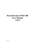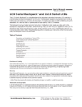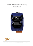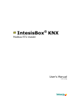
1
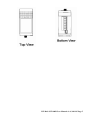
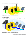
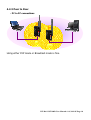
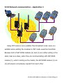
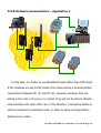
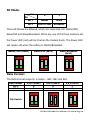
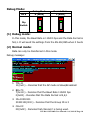
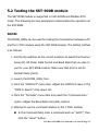
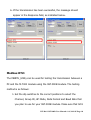
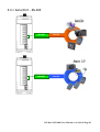
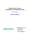
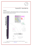
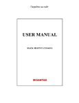
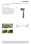
SST-900B Wireless Modem User Manual Warranty All products manufactured by ICP DAS are warranted against defective materials for a period of one year from the date of delivery to the original purchaser. Warning ICP DAS assumes no liability for damages consequent to the use of this product. ICP DAS reserves the right to change this manual at any time without notice. The information furnished by ICP DAS is believed to be accurate and reliable. However, no responsibility is assumed by ICP DAS for its use, nor for any infringements of patents or other rights of third parties resulting from its use. Copyright Copyright 2010 by ICP DAS. All rights are reserved. Trademark Names are used for identification only and may be registered trademarks of their respective companies. ICP DAS SST-900B User Manual v1.0, 2011/05 Page 1 Table of Contents 1. Introduction ............................................................................. 3 2. Specifications:.......................................................................... 4 3. Product Description ................................................................. 5 3.1 Internal I/O Structure ........................................................... 5 3.2 Appearance .......................................................................... 5 3.3 Dimensions (Units: mm)........................................................ 6 4. Applications ............................................................................. 8 4.1 Operating Modes .................................................................. 8 4.2 Application Example .............................................................. 8 5. Quick Start instructions for the SST-900B........................... 13 5.1 SST-900B Dip Switch Information ........................................ 13 5.2 Testing the SST-900B module.............................................. 17 5.3 Installing the Hardware ....................................................... 20 ICP DAS SST-900B User Manual v1.0, 2011/05 Page 2 1. Introduction The SST-900B module is integrated for data acquisition and control application between a host and remote sensors, and it provides a better solution for environments where wiring is difficult. The SST-900B module is a wireless module that works in a frequency range of 902-928 MHz, and includes adjustable 16 RF channels and each channel can be allocated one of sixteen group IDs. If data is to be transferred from one SST-900B module to another, the channel number and the group ID number must be the same on both modules. Both RS-232 and RS-485 interfaces are supported, and the module can be configured to operate in either broadcast or peer-to-peer transmission mode. All configurations can be completed using the external switches. Connection interfaces are mutually exclusive, meaning that a connection to the RS-485 can’t be made when using the RS-232, and vice versa. In broadcast mode, all SST-900B modules operate in slave mode, so they are able to receive transmissions from each other. In peer-to-peer mode, however, although a multiple number of masters and slaves, exist also known as a multi-point structure, the master will only receive transmissions from the slave and vice versa. ICP DAS SST-900B User Manual v1.0, 2011/05 Page 3 2. Specifications: Operating Frequency of 902-928 MHz. T ypical wireless transmission range is 1000 meters (LOS) UI Configuration via external switch Module Modulation Technique Wireless RF Channels Receive Sensitivity Transmit Power Antenna SST-900B FSK (Frequency-shift keying) 16 -100 dBm @ 150k bps Up to 20 dBm 3 dBi Omni-directional antenna, Reverse Polarity SMA (RP-SMA) Plug (Male) 1000 meters (LOS) 150k bps Transmission Range Maximum RF Data Rate General CPU 8051 Module Type Master, Slave Communication Interface RS-232 COM0 RS-485 COM0 Settings Baud Rate 1200~115200 bps Data Bit 8 Parity Check Even, Odd, None Stop Bit 1 LED Indicators Green RF TxD Yellow RF RxD Red Power State Power EMS Protection ESD, Surge, EFT and Hi-Pot Required Supply +10 VDC ~ +30 VDC Power Consumption 0.48W 8-pin 5.08 ㎜ Removable Terminal Block Connection Mechanical Casing Plastic Flammability UL 94V-0 materials Dimensions 84㎜ (W) x 108㎜ (L) x 33㎜ (H) (W × L × H) Weight 160 g Installation DIN-Rail Environment Operating Temperature -25 ~ +75℃ -40 ~ +80℃ Storage Temperature Relative Humidity 0~90% RH, non-condensing ICP DAS SST-900B User Manual v1.0, 2011/05 Page 4 3. Product Description 3.1 Internal I/O Structure TX RX GND RS-232 Interface D+ D- RS-485 Interface VS+ GND Power Regulator Embedded Controller RF Module Configuration Switch 3.2 Appearance ICP DAS SST-900B User Manual v1.0, 2011/05 Page 5 3.3 Dimensions (Units: mm) ICP DAS SST-900B User Manual v1.0, 2011/05 Page 6 ICP DAS SST-900B User Manual v1.0, 2011/05 Page 7 4. Applications 4.1 Operating Modes Interface Serial Port Mode SST-900B SST-900B Master Slave Slave Master Slave Slave Peer-to-Peer (RS-232/RS-485) Broadcast 4.2 Application Example What is the difference between P2P (peer-to-peer) mode and Broadcast mode? In broadcast mode, all the nodes act as slaves, and there can be communication between any two nodes. In P2P mode, the effect of a master to slave framework or a slave to master framework is identical. The master will only receive data from the slave and, similarly, a slave will only receive data from the master. In most cases, using either P2P mode or Broadcast mode is suitable. But in multi-point cases, there may be better scenarios, which are described in the following sections: ICP DAS SST-900B User Manual v1.0, 2011/05 Page 8 4.2.1 Connecting a PC to the 7000 module Using either P2P mode or Broadcast mode is fine. 4.2.2 Peer-to-Peer - Using a 7188 module as a Bridge to connect to a 7000 series module Using either P2P mode or Broadcast mode is fine. ICP DAS SST-900B User Manual v1.0, 2011/05 Page 9 4.2.3 Peer to Peer - PC to PC connections Using either P2P mode or Broadcast mode is fine. ICP DAS SST-900B User Manual v1.0, 2011/05 Page 10 4.2.4 Network communication – Application 1 1 2 3 Using P2P mode is more suitable than Broadcast mode. Here is a suitable where setting the modules to P2P mode would be beneficial. Because both of SST-900B modules (2) and (3) are neither acting in the same roles as a slave, when they are communicating with SST-900B module (1), which is acting as the master, the SST-900B module (2) nor (3) will acquire unnecessary signals from each other. ICP DAS SST-900B User Manual v1.0, 2011/05 Page 11 4.2.5 Network communication – Application 2 1 2 In this case, it is better to use Broadcast mode rather than P2P mode. If the modules are set to P2P mode, then there will be a communication requirement between PC (1) and PC (2). However, because they are acting in the roles of a server or a client, they will not be able to directly communicate with each other. So, in this situation, it would be better to set the modules to broadcast mode, in order to allow communication between two nodes. ICP DAS SST-900B User Manual v1.0, 2011/05 Page 12 5. Quick Start instructions for the SST-900B 5.1 SST-900B Dip Switch Information 8 67 9A 4 3 2 1 0F Channel B 5 C 4 D 3 8 67 9A 2 1 0FE B C D ON ON 1 2 3 4 5 6 7 8 AP Mode Group ID Data Format Baud Rate Debug Mode RF Channel: The same channel of each module will be connected. SST-900B supports 16 channels. Group ID: The same Group ID of each module will be connected. SST-900B supports 16 Group ID. ICP DAS SST-900B User Manual v1.0, 2011/05 Page 13 AP Mode: Value 0 1 Bit 1 Master Slave Bit 2 Peer-to-Peer Broadcast Bit Three AP Modes are allowed, which are separated into Master/P2P, Slave/P2P and Slave/Broadcast. When any one of the three modes is set, the Power LED (red) will be lit when the module boots. The Power LED will remain off when the setting is Master/Broadcast. Master/P2P (0x00) Slave/P2P (0x10) ON 1 Slave/Broadcast (0x11) ON 2 1 ON 2 1 2 Data Format: The Data Format supports 3 modes – N81, O81 and E81. Data format Bit 3 Bit 4 N,8,1 (0x00) 0 0 ON O,8,1 (0x01) 0 1 ON E,8,1 (0x10) 1 0 ON Dip Switch 3 4 3 4 3 4 ICP DAS SST-900B User Manual v1.0, 2011/05 Page 14 Baud Rate: Baud Rate 1200 (0x00) 2400 (0x01) 4800 (0x02) 9600 (0x03) Bit 5 Bit 6 Bit 7 0 0 0 0 0 1 ON 0 1 0 ON 0 1 1 ON ON Dip Switch 5 Baud Rate Bit 5 Bit 6 Bit 7 6 7 19200 (0x04) 1 0 0 5 6 7 38400 (0x05) 1 0 1 ON 5 6 7 57600 (0x06) 1 1 0 ON 5 6 7 115200 (0x07) 1 1 1 ON ON Dip Switch 5 6 7 5 6 7 5 6 7 5 6 7 ICP DAS SST-900B User Manual v1.0, 2011/05 Page 15 Debug Mode: Bit 8 Debug Mode 0 (0x00) Normal Mode 1 (0x01) ON ON 8 8 Dip Switch (1) Debug mode: In this mode, the Baud Rate is 115200 bps and the Data Format is N.8,1. It will send the settings from the RS-232/485 when it boots (2) Normal mode: Data can only be transferred in this mode. Debug message: 1. TM=11 11(0x11) – Denotes that the AP mode is Slave/Broadcast 2. BD=70 7(0x111) - Denotes that the Baud Rate 115200 bps 0(0x00) - Denotes that the Data Format is N,8,1 3. ID=30303131 30303131(0011) - Denotes that the Group ID is 3 4. CH=0C 0C(0x0C) - Denotes that channel C is being used. ICP DAS SST-900B User Manual v1.0, 2011/05 Page 16 5.2 Testing the SST-900B module The SST-900B module is supported in both DCON and Modbus RTU mode. The following are two examples to demonstrate the operation od the SST-900B. DCON: The DCON_Utility can be used for testing the transmission between a PC and the I-7000 module using the SST-900B module. The testing method is as follows: 1. Set the dip switches to the correct positions to select the Channel, Group ID, AP Mode, Data Format and Baud Rate that you plan to use for your SST-900B module. Make sure that bit 8 is set for Normal Mode (0x01). 2. Launch the DCON_Utility tool. 3. Click the “COM Port” menu item. Adjust the COM Port value in the “COM to Search” drop down list. 4. Click the “Terminal” menu item and select the “Command Line” option. Adjust the Baud Rate and parity options. 5. Attempt to send a command relative to the I-7000 module. In the Command field, enter a command such as “$01M ”, then click the “Send ” button. ICP DAS SST-900B User Manual v1.0, 2011/05 Page 17 6. If the transmission has been successful, the message should appear in the Response field, as indicated below. Modbus RTU: The MBRTU_Utility can be used for testing the transmission between a PC and the M-7000 module using the SST-900B module. The testing method is as follows: 1. Set the dip switches to the correct positions to select the Channel, Group ID, AP Mode, Data Format and Baud Rate that you plan to use for your SST-900B module. Make sure that bit 8 ICP DAS SST-900B User Manual v1.0, 2011/05 Page 18 is set for Normal Mode (0x01). 2. Launch the MBRTU_Utility tool. 3. Select the number of the COM Port you want, then adjust the Baud Rate and enter the data format in the “Line Control” filed. Remember to click “Open”. 4. Attempt to send a command relative to the M-7000 module. In the Command field, enter a command such as “1 1 0 0 0 1”, then click the “Send Command” button. 5. If the transmission has been successful, the message should appear in the Response field, as indicated below. ICP DAS SST-900B User Manual v1.0, 2011/05 Page 19 5.3 Installing the Hardware 5.3.1 Serial Port - RS-232 RxD TxD GND RS-232 Port RxD TxD GND RS-232 Port ICP DAS SST-900B User Manual v1.0, 2011/05 Page 20 5.3.1 Serial Port - RS-485 RS-485 D+/D- RS-485 D+/D- ICP DAS SST-900B User Manual v1.0, 2011/05 Page 21