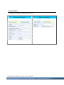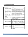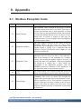
1
GW-7662 User Manual Version 1.00, Jan. 2015 Written by Ryan Lin Warranty All products manufactured by ICP DAS are under warranty regarding defective materials for a period of one year, beginning from the date of delivery to the original purchaser. Warning ICP DAS assumes no liability for any damage resulting from the use of this product.ICP DAS reserves the right to change this manual at any time without notice. The information furnished by ICP DAS is believed to be accurate and reliable. However, no responsibility is assumed by ICP DAS for its use, not for any infringements of patents or other rights of third parties resulting from its use. Copyright Copyright @ 2015 by ICP DAS Co., Ltd. All rights are reserved. Trademark The names used for identification only may be registered trademarks of their respective companies. Contact US If you have any problem, please feel free to contact us. You can count on us for quick response. Email: [email protected] GW-7662 User Manual (Version 1.00, Jan/2015) Page: 2 Copyright © 2015 ICP DAS Co., Ltd. All Rights Reserved. E-mail: [email protected] Table of Contents Table of Contents ...................................................................................3 1. Introduction ........................................................................................5 1.1. Features ....................................................................................................... 6 1.2. Specification ................................................................................................. 7 1.3. Internal I/O Structure .................................................................................... 9 1.4. Pin Assignment........................................................................................... 10 1.5. Overview .................................................................................................... 12 1.6. Wiring and Jumper Setting Instructions ...................................................... 16 1.6.1. RS-232 Connection .......................................................................... 16 1.6.2. RS-422 Connection .......................................................................... 17 1.6.3. RS-485 Connection .......................................................................... 18 1.7. Dimensions................................................................................................. 20 2. PROFINET .........................................................................................21 2.1. Device classes of PROFINET IO................................................................ 21 2.2. Device Description...................................................................................... 22 2.3. Conformance Classes (CC)........................................................................ 23 3. Basic Application .............................................................................25 3.1. Connect to Network, PC and PROFINET IO controller............................... 25 3.2. Network configuration................................................................................. 26 3.3. GSD Import ................................................................................................ 34 3.4. Project Setup.............................................................................................. 36 4. Communication ................................................................................44 4.1. Communication Sequence ......................................................................... 44 GW-7662 User Manual (Version 1.00, Jan/2015) Page: 3 Copyright © 2015 ICP DAS Co., Ltd. All Rights Reserved. E-mail: [email protected] 4.2. Module configuration .................................................................................. 48 4.3. PROFINET Input Data Area........................................................................ 49 4.4. PROFINET Output Data Area..................................................................... 50 4.5. Diagnostic Messages ................................................................................. 51 4.6. Data exchange example............................................................................. 52 4.6.1. PLC receives DO status from Modbus master ................................. 53 4.6.2. PLC refreshes DI status to Modbus master...................................... 55 5. MiniOS7 Utility Tool..........................................................................57 5.1. Installing the MiniOS7 Utility ....................................................................... 57 5.2. Using MiniOS7 Utility to get Ethernet settings and firmware version .......... 58 6. PFN_Tool Utility ................................................................................60 6.1. Installing the PFN_Tool Utility ..................................................................... 60 6.2. PFN_Tool Utility Functionalities .................................................................. 61 6.2.1. Module Search ................................................................................. 61 6.2.2. Module Basic Configuration.............................................................. 62 6.2.3. Module Advanced Configuration....................................................... 64 7. Configuration with Web Browser....................................................73 7.1. Connecting to Web Server ......................................................................... 73 7.2. Web Configuration...................................................................................... 74 8. Troubleshooting ...............................................................................79 9. Appendix ...........................................................................................80 9.1. Modbus Exception Code ............................................................................ 80 GW-7662 User Manual (Version 1.00, Jan/2015) Page: 4 Copyright © 2015 ICP DAS Co., Ltd. All Rights Reserved. E-mail: [email protected] 1. Introduction PROFINET is an open Industrial Ethernet standard developed by the PROFIBUS Organization (PI). Based on Ethernet versatility, PROFINET make vertical integration of field level with Enterprise level easily. PROFINET is automation in real time, so it can cover all requirements of the Automation Industry. PROFINET is fit for factory automation, process automation, safety applications and motion control applications, etc. PROFINET contains 2 different solutions. They are PROFINET IO and PROFINET CBA (Component Based Automation). GW-7662 module are PROFINET IO device. The user can access and configure the modules easily by using the GSDML file in any PROFINET Engineering tool, and exchange process data quickly with the IO controller. GW-7662 User Manual (Version 1.00, Jan/2015) Page: 5 Copyright © 2015 ICP DAS Co., Ltd. All Rights Reserved. E-mail: [email protected] 1.1. Features Transfer protocol: PROFINET IO Supported Ethernet services: ICMP, IGMP, ARP, DHCP, TELNET, TFTP, SNMP, VLAN Priority Tagging Supported PROFINET services: RTC, RTA, CL-RPC, DCP, LLDP, I&M PROFINET Conformance Class B and RT Class 1 Cyclic Time: 1ms (min) Generic GSDML File Provided Max. Input/Output data :512/512 bytes Support Modbus Master and Slave mode Support Modbus RTU and ASCII format Support several kinds of baud rate for COM1 from 1.2 to 460.8 kbps Built-in self-tuner ASIC controller on RS-422/485 port Integrated 2-Port Switch Automatic MDI / MDI-X Crossover for Plug-and-play Provide LED indicators Robust, fan less design 4 kV Contact ESD protection for any terminal Wide range of power input (+10 ~ +30 VDC) and operating temperature (-25 ~ +75°C) GW-7662 User Manual (Version 1.00, Jan/2015) Page: 6 Copyright © 2015 ICP DAS Co., Ltd. All Rights Reserved. E-mail: [email protected] 1.2. Specification Hardware CPU 32-bit CPU Core RAM/Flash/EEPROM 32 MB / 4 MB / 8 KB Watchdog CPU built-in ESD Protection 4 kV class A PROFINET Interface Protocol PROFINET IO Device Conformance Classes Class B Services RTC, RTA, CL-RPC, DCP, LLDP, I&M Cycle Time 1 ms (min.) Ethernet Interface Controller 10/100Base-TX Ethernet Controller (Auto-negotiating, Auto_MDIX) Connector RJ-45 x 2 (LED indicators) , Integrated 2-Port Switch Services ICMP, IGMP, ARP, DHCP, TELNET, TFTP, SNMP, VLAN Priority Tagging UART Interface COM RS-232/RS-422/RS-485 (can’t be used simultaneously) COM Connector 3-pin screwed terminal block (RxD, TxD, GND) 4-pin screwed terminal block (RxD+, RxD-, TxD+, TxD-) 2-pin screwed terminal block (DATA+, DATA-) Baud Rate (bps) 1200, 2400, 4800, 9600, 19200, 38400, 57600, 115200, 230400, 460800 Data bit 7, 8 GW-7662 User Manual (Version 1.00, Jan/2015) Page: 7 Copyright © 2015 ICP DAS Co., Ltd. All Rights Reserved. E-mail: [email protected] Stop bit 1 Parity None, Even, Odd LED Display Round LED AP LED, BOOT LED, ERR LED Power Requirements Power supply Unregulated +10 ~ +30 VDC Protection Power reverse polarity protection, Over-voltage brown-out protection Power Consumption 3.4 W Mechanical Dimensions 42 mm x 76 mm x 119 mm (W x L x H) Installation DIN Rail or Wall mounting Environment Operating Temperature -25 ˚C ~ +75 ˚C Storage Temperature -30 ˚C ~ +80 ˚C Humidity 10~ 90 % RH, non-condensing GW-7662 User Manual (Version 1.00, Jan/2015) Page: 8 Copyright © 2015 ICP DAS Co., Ltd. All Rights Reserved. E-mail: [email protected] 1.3. Internal I/O Structure GW-7662 User Manual (Version 1.00, Jan/2015) Page: 9 Copyright © 2015 ICP DAS Co., Ltd. All Rights Reserved. E-mail: [email protected] 1.4. Pin Assignment Pin Name 1 - 2 3 4 5 6 7 8 9 DD+ RxRx+ Description N/A Data- of RS-485 Data+ of RS-485 N/A N/A N/A N/A Receive Data- of RS-422 Receive Data+ of RS-422 GW-7662 User Manual (Version 1.00, Jan/2015) Page: 10 Copyright © 2015 ICP DAS Co., Ltd. All Rights Reserved. E-mail: [email protected] 10 11 12 13 14 15 16 17 18 TxTx+ GND Rx Tx Transmit Data- of RS-422 Transmit Data+ of RS-422 N/A N/A N/A N/A GND of RS-232 Receive Data of RS-232 Transmit Data of RS-232 GW-7662 User Manual (Version 1.00, Jan/2015) Page: 11 Copyright © 2015 ICP DAS Co., Ltd. All Rights Reserved. E-mail: [email protected] 1.5. Overview Here is a brief overview of the components and its descriptions for module status. UART Connector For more detailed information regarding the pin assignments of the UART Connector, please refer to “1.4. Pin Assignment” GW-7662 User Manual (Version 1.00, Jan/2015) Page: 12 Copyright © 2015 ICP DAS Co., Ltd. All Rights Reserved. E-mail: [email protected] Status LED Indicators AP mode: AP BOOT OFF OFF ERR Description Flash waiting for PROFINET connection (Slow) ON OFF ON OFF OFF PROFINET connection is established. Flash Device is at AP mode and the module received the incorrect parameters. (Slow) Flash ON OFF Error! GW-7662 has diagnostic message. (Fast) Flash Flash (Slow) (Slow) ON Hardware authentication error! Bootloader mode: AP BOOT ERR Description ON ON OFF waiting for Ethernet link OFF ON OFF Ethernet link established, waiting for IP address acquired ON OFF IP address acquired, waiting for telnet connection ON OFF Telnet connection is established. Flash (Slow) ON Flash(Slow): about 500ms Flash(Fast): about 100ms GW-7662 User Manual (Version 1.00, Jan/2015) Page: 13 Copyright © 2015 ICP DAS Co., Ltd. All Rights Reserved. E-mail: [email protected] Ethernet Ports An Ethernet port is an opening on GW-7662 network equipment that Ethernet cables plug into. Ethernet ports accept cables with RJ-45 connectors. Tips & Warnings 1. When users connect GW-7662 and switch, users should not connect LAN1 and LAN2 to switch at the same time, else it will lead to abnormal network. 2. When users connect network devices by daisy chain topology, users can connect these devices in series by LAN1 and LAN2. Rotary Switch Position Mode 0 AP mode Module configuration Output: 32 bytes Input: 32 bytes Output: 64 bytes 1 AP mode Input: 64 bytes Output: 128 bytes 2 AP mode Input: 128 bytes Output: 256 bytes 3 AP mode Input: 256 bytes Output: 384 bytes 4 AP mode Input: 384 bytes Output: 512 bytes 5 AP mode Input: 512 bytes 6~7 AP mode Reserved 8~F Bootloader mode N/A GW-7662 User Manual (Version 1.00, Jan/2015) Page: 14 Copyright © 2015 ICP DAS Co., Ltd. All Rights Reserved. E-mail: [email protected] Tips & Warnings If AP LED turn on, BOOT LED turn off and ERR LED flash slow. It means that the value of rotary switch does not match the settings of the modules(please refer to section 4.2. Module configuration). Power Connector Pin Name Function +VS 10 ~ 30 VDC power input GND Ground connection F.G. Frame ground connection GW-7662 User Manual (Version 1.00, Jan/2015) Page: 15 Copyright © 2015 ICP DAS Co., Ltd. All Rights Reserved. E-mail: [email protected] 1.6. Wiring and Jumper Setting Instructions It is recommended to use only one serial port (RS232, RS485 or RS422) of the converter at the same time. The following section describes the necessary steps to be taken to connect one of the three COM port types to a serial device or serial network. The pull high/low resistor of COM port is shown in below. 1.6.1. RS-232 Connection The RS-232 port of the GW-7662 has got three pins. GW-7662 User Manual (Version 1.00, Jan/2015) Page: 16 Copyright © 2015 ICP DAS Co., Ltd. All Rights Reserved. E-mail: [email protected] 1.6.2. RS-422 Connection The GW-7662 converter is always a PROFINET IO device but it can in a local RS-422 network either take the position of a master or that of a slave. Depending on whether the converter acts as a local master or as a slave and on the number of devices connected to the RS-422 network device the four jumpers provided by the module has to be set. The jumpers set the pull high and pull down resistors for the RS-422 port. Configuration of pull high/low resistor for the RS-422 port Pull High/Low resistor Condition The GW-7662 is the master in RS-422 bus Enable (default) or The number of devices connected to the RS-422 bus is less than 10 The GW-7662 is a slave in RS-422 bus Disable or The number of devices connected to the RS-422 bus is more than 10 GW-7662 User Manual (Version 1.00, Jan/2015) Page: 17 Copyright © 2015 ICP DAS Co., Ltd. All Rights Reserved. E-mail: [email protected] 1.6.3. RS-485 Connection The GW-7662 converter can only act in the PROFINET network as a slave. In a RS-485 network however it can either be a local master or slave. Before the module is connected to a RS-485 network it is important to know whether the module takes the place of a slave or master and how many devices are active on the RS-485 bus. The two jumpers (JP7 and JP8) have to be set according the bus configuration. Configuration of pull high/low resistor for the RS-485 port Pull High/Low resistor Condition The GW-7662 is the master in RS-485 bus Enable (default) or The number of devices connected to the RS-485 bus is less than 10 The GW-7662 is a slave in RS-485 bus Disable or The number of devices connected to the RS-485 bus is more than 10 GW-7662 User Manual (Version 1.00, Jan/2015) Page: 18 Copyright © 2015 ICP DAS Co., Ltd. All Rights Reserved. E-mail: [email protected] GW-7662 User Manual (Version 1.00, Jan/2015) Page: 19 Copyright © 2015 ICP DAS Co., Ltd. All Rights Reserved. E-mail: [email protected] 1.7. Dimensions GW-7662 User Manual (Version 1.00, Jan/2015) Page: 20 Copyright © 2015 ICP DAS Co., Ltd. All Rights Reserved. E-mail: [email protected] 2. PROFINET PROFINET contains 2 different solutions. They are PROFINET IO and PROFINET CBA (Component Based Automation). GW-7662 module is a PROFINET IO device. PROFINET IO is used for communication with decentral periphery like IOs, drives, etc. PROFINET CBA is a communication solution for autonomously acting partial units of machines or plants. 2.1. Device classes of PROFINET IO The following devices classes are defined to facilitate structuring of PROFINET IO field devices. IO-Controller: This is typically a PLC on which the automation program runs IO-Supervisor: This can be a programming device (PG), personal computer (PC), or human machine interface (HMI) device for commissioning or diagnostic purposes. IO-Device: An IO-Device is a distributed I/O field device that is connected via PROFINET IO. It can exchange data with multiple IO-Controllers. GW-7662 User Manual (Version 1.00, Jan/2015) Page: 21 Copyright © 2015 ICP DAS Co., Ltd. All Rights Reserved. E-mail: [email protected] 2.2. Device Description The functionality of a PROFINET IO Device is always described in a GSD file. This file contains all data that are relevant for engineering as well as for data exchange with IO-Device. PROFINET IO-Devices can be described using XML-based GSD. The description language of the GSD file, i.e. GSDML (General Station Description Markup Language) is based on international standards. Every manufacturer of a PROFINET IO-Device must supply an associated GSD file according to the GSDML specification. Users can access and configure GW-7662 module by using the GSDML file in any PROFINET Engineering tool. GW-7662 User Manual (Version 1.00, Jan/2015) Page: 22 Copyright © 2015 ICP DAS Co., Ltd. All Rights Reserved. E-mail: [email protected] 2.3. Conformance Classes (CC) PI has classified the scope of functions in PROFINET IO into 3 conformance classes (CC-A, CC-B, CC-C). Users simply need to select a CC appropriate for system and do not need to worry about any other details to ensure the interoperability in an automation system with regard to the scope of functions and performance parameters. CC-A: Use of the infrastructure of an existing Ethernet network including integration of basic PROFINET functionality. All IT services can be used without restrictions. Examples of typical applications are in building automation and process automation. Wireless communication is only possible in this class. CC-B: In addition to the functions of CC-A, the scope of functions of CC-B supports easy and user-friendly device replacement without the need for an engineering tool. Examples of typical applications are in automation systems with a higher-level machine controller that place relatively low demands for a deterministic data cycle. CC-C: In addition to the functions of CC-B, the scope of functions of CC-C supports high-precision and deterministic data transmission, including for isochronous applications. An example of a typical application is the field of motion control. GW-7662 User Manual (Version 1.00, Jan/2015) Page: 23 Copyright © 2015 ICP DAS Co., Ltd. All Rights Reserved. E-mail: [email protected] GW-7662 User Manual (Version 1.00, Jan/2015) Page: 24 Copyright © 2015 ICP DAS Co., Ltd. All Rights Reserved. E-mail: [email protected] 3. Basic Application If you are a new user, begin with this chapter, it includes a guided tour that provides a basic overview of installing, configuring and using the GW-7662. In the following examples the S7-1200 PLC from Siemens is used to be a PROFINET IO Controller. The configuration and communication is done by the program “Step 7 V11 SP2 (TIA PORTAL)” provided by Siemens. 3.1. Connect to Network, PC and PROFINET IO controller The GW-7662 module is equipped with two RJ-45 Ethernet ports for connection to an Ethernet switch, PC and PROFINET IO controller. Tips & Warnings 1. When users connect GW-7662 and switch, users should not connect LAN1 and LAN2 to switch at the same time, else it will lead to abnormal network. 2. When users connect network devices by daisy chain topology, users can connect these devices in series by LAN1 and LAN2. GW-7662 User Manual (Version 1.00, Jan/2015) Page: 25 Copyright © 2015 ICP DAS Co., Ltd. All Rights Reserved. E-mail: [email protected] 3.2. Network configuration In this example, please follow the below configuration to configure the network. PC: IP: 192.168.6.210 Mask: 255.255.0.0 PLC: Device name: plc1 IP: 192.168.6.211 Mask: 255.255.0.0 GW-7662: Device name: gw-7662 IP: 192.168.6.212 Mask: 255.255.0.0 GW-7662 User Manual (Version 1.00, Jan/2015) Page: 26 Copyright © 2015 ICP DAS Co., Ltd. All Rights Reserved. E-mail: [email protected] Step 1: Set PC’s IP Click “start->Settings->Network Connections” Double click “Local Area Connection” icon Click “Properties” button GW-7662 User Manual (Version 1.00, Jan/2015) Page: 27 Copyright © 2015 ICP DAS Co., Ltd. All Rights Reserved. E-mail: [email protected] Select “Internet Protocol(TCP/IP)” and click “Properties” button Set “Internet Protocol Properties” and then click “OK” button. GW-7662 User Manual (Version 1.00, Jan/2015) Page: 28 Copyright © 2015 ICP DAS Co., Ltd. All Rights Reserved. E-mail: [email protected] Step 2: Set PLC’s name and IP Double Click TIA icon to start Step 7 V11 Click “Project view” Search accessible devices GW-7662 User Manual (Version 1.00, Jan/2015) Page: 29 Copyright © 2015 ICP DAS Co., Ltd. All Rights Reserved. E-mail: [email protected] Select PLC and click “Online & diagnostics” button Set IP and Mask GW-7662 User Manual (Version 1.00, Jan/2015) Page: 30 Copyright © 2015 ICP DAS Co., Ltd. All Rights Reserved. E-mail: [email protected] Set device name Step 3: Set GW-7662 module’s name and IP Search accessible devices GW-7662 User Manual (Version 1.00, Jan/2015) Page: 31 Copyright © 2015 ICP DAS Co., Ltd. All Rights Reserved. E-mail: [email protected] Select GW-7662 module and click “Online & diagnostics” button Set IP and Mask GW-7662 User Manual (Version 1.00, Jan/2015) Page: 32 Copyright © 2015 ICP DAS Co., Ltd. All Rights Reserved. E-mail: [email protected] Set device name GW-7662 User Manual (Version 1.00, Jan/2015) Page: 33 Copyright © 2015 ICP DAS Co., Ltd. All Rights Reserved. E-mail: [email protected] 3.3. GSD Import In this example, please follow the step to import GSD file. Step 1: Get GSD file The GSD file can be obtained from companion CD or our FTP site: CD: \fieldbus_cd\profinet\gateway\gw-7662\gsd\ ftp://ftp.icpdas.com/pub/cd/fieldbus_cd/profinet/gateway/gw-7662/gsd/ Step 2: Import GSD file Double Click TIA icon to start Step 7 V11 Click “Project view” GW-7662 User Manual (Version 1.00, Jan/2015) Page: 34 Copyright © 2015 ICP DAS Co., Ltd. All Rights Reserved. E-mail: [email protected] Select “Menu->Options->Install general station description file (GSD)” Select and install GSD file GW-7662 User Manual (Version 1.00, Jan/2015) Page: 35 Copyright © 2015 ICP DAS Co., Ltd. All Rights Reserved. E-mail: [email protected] 3.4. Project Setup In this example, please follow the step to setup project. Step 1: Create the project Double Click TIA icon to start Step 7 V11 Create the Project GW-7662 User Manual (Version 1.00, Jan/2015) Page: 36 Copyright © 2015 ICP DAS Co., Ltd. All Rights Reserved. E-mail: [email protected] Step 2: Project configuration Add a PLC device GW-7662 User Manual (Version 1.00, Jan/2015) Page: 37 Copyright © 2015 ICP DAS Co., Ltd. All Rights Reserved. E-mail: [email protected] Set the device name of PLC to “PLC_1” Set the IP and mask of PLC and add a new subnet GW-7662 User Manual (Version 1.00, Jan/2015) Page: 38 Copyright © 2015 ICP DAS Co., Ltd. All Rights Reserved. E-mail: [email protected] Add GW-7662 module Select PROFINET interface GW-7662 User Manual (Version 1.00, Jan/2015) Page: 39 Copyright © 2015 ICP DAS Co., Ltd. All Rights Reserved. E-mail: [email protected] Set device name to “gw-7662” Set the IP of GW-7662 module GW-7662 User Manual (Version 1.00, Jan/2015) Page: 40 Copyright © 2015 ICP DAS Co., Ltd. All Rights Reserved. E-mail: [email protected] Select module type of GW-7662 module Compile and download to device GW-7662 User Manual (Version 1.00, Jan/2015) Page: 41 Copyright © 2015 ICP DAS Co., Ltd. All Rights Reserved. E-mail: [email protected] GW-7662 User Manual (Version 1.00, Jan/2015) Page: 42 Copyright © 2015 ICP DAS Co., Ltd. All Rights Reserved. E-mail: [email protected] At this time, the AP LED should turn on, BOOT LED and ERR LED should turn off, it means the connection between PLC and GW-7662 module is established. GW-7662 User Manual (Version 1.00, Jan/2015) Page: 43 Copyright © 2015 ICP DAS Co., Ltd. All Rights Reserved. E-mail: [email protected] 4. Communication 4.1. Communication Sequence GW-7662 module has basically got 6 buffers: PROFINET IO device input buffer PROFINET IO device output buffer DI buffer DO buffer AI buffer AO buffer PROFINET IO controller has basically got 2 buffers: PROFINET IO controller input buffer PROFINET IO controller output buffer PROFINET Data Exchange During each message cycle PROFINET IO controller writes the content of its output buffer to PROFINET IO device input buffer and reads the content of PROFINET IO device output buffer to its input buffer. The exchange cycle is taking place even though the content of the PROFINET IO controller and PROFINET IO device output buffer has not changed. The data flow between PROFINET IO controller and GW-7662 is shown in below. GW-7662 User Manual (Version 1.00, Jan/2015) Page: 44 Copyright © 2015 ICP DAS Co., Ltd. All Rights Reserved. E-mail: [email protected] Modbus Data Exchange – Master mode When GW-7662 acts as a Modbus master device, it can get query message through parameters set by PFN_Tool Utility and DO, AO buffer, and then send query message to Modbus slave device. It can also receive response message from Modbus slave device and then saving to internal DI, AI buffer. GW-7662 User Manual (Version 1.00, Jan/2015) Page: 45 Copyright © 2015 ICP DAS Co., Ltd. All Rights Reserved. E-mail: [email protected] GW-7662 send data to Modbus slave device GW-7662 receive data from Modbus slave device GW-7662 User Manual (Version 1.00, Jan/2015) Page: 46 Copyright © 2015 ICP DAS Co., Ltd. All Rights Reserved. E-mail: [email protected] Modbus Data Exchange – Slave mode When GW-7662 acts as a Modbus slave device, it can receive query message from Modbus master device and then saving to internal DO, AO buffer. It can also send response message to Modbus master device through internal DI, AI buffer. GW-7662 receive data from Modbus master device GW-7662 output data to Modbus master device GW-7662 User Manual (Version 1.00, Jan/2015) Page: 47 Copyright © 2015 ICP DAS Co., Ltd. All Rights Reserved. E-mail: [email protected] 4.2. Module configuration The user can set the size of the I/O modules in the PROFINET configuration tool. Each I/O module will allocate input 8 bytes and output 8 bytes for system. The settings of the modules are described below. Max. I/O modules: 1 “RSW:0 Input:32Byte Output:32Byte” module ”RSW:1 Input:64Byte Output:64Byte” module ”RSW:2 Input:128Byte Output:128Byte” module ”RSW:3 Input:256Byte Output:256Byte” module ”RSW:4 Input:384Byte Output:384Byte” module ”RSW:5 Input:512Byte Output:512Byte” module Tips & Warnings If AP LED turn on, BOOT LED turn off and ERR LED flash slow. It means that the value of rotary switch does not match the settings of the modules(please refer to section 1.5. Overview -> Rotary Switch). GW-7662 User Manual (Version 1.00, Jan/2015) Page: 48 Copyright © 2015 ICP DAS Co., Ltd. All Rights Reserved. E-mail: [email protected] 4.3. PROFINET Input Data Area The maximum input data length of GW-7662 is 512 bytes. The first 8 bytes of the received input data are reserved for the communication status. The remaining data in the input data area represents the data packet received from the Modbus network. Byte Description 1 2 3 4 5~8 9~512 The number of diagnostic messages Type of diagnostic messages Description of diagnostic messages Current used Modbus command module Reserved Received data from Modbus network Diagnostic message (byte 1~3) EX: the data in byte1~3 is “0x02 0x01 0x0C”. It means there are 2 diagnostic messages and the first message is “Modbus command module 1 send query message to Modbus slave device and doesn’t receive any response message”. “02” “01” “0C” There are 2 diagnostic messages Module 1 Error Response Message Timeout Received data (byte 9~512) For more detail information, please refer to section 4.6.1. PLC receives DO status from Modbus master GW-7662 User Manual (Version 1.00, Jan/2015) Page: 49 Copyright © 2015 ICP DAS Co., Ltd. All Rights Reserved. E-mail: [email protected] 4.4. PROFINET Output Data Area The maximum output data length of GW-7662 is 512 bytes. The first 8 bytes are belong to communication commands. Byte Description 1 2 3~8 9~512 Reserved Control bit Reserved Output data to Modbus network Control bit (byte 2) Bit 0: When this bit is set, diagnostic messages send by the GW-7662 module will all be cleared. Bit 1~7: The remaining bits have to be set to zero. Output data (byte 9~512) For more detail information, please refer to section 4.6.2. PLC refreshes DI status to Modbus master. GW-7662 User Manual (Version 1.00, Jan/2015) Page: 50 Copyright © 2015 ICP DAS Co., Ltd. All Rights Reserved. E-mail: [email protected] 4.5. Diagnostic Messages The GW-7662 module can record maximally 32 diagnostic messages at the same time. If the number of the diagnostic messages is bigger than 32, the GW-7662 will not process other diagnostic message. Type Module 1~128 Error (0x01~0x0D) Description Illegal Function (0x01) Illegal Data Address (0x02) Illegal Data Value (0x03) Slave Device Failure (0x04) Acknowledge (0x05) Slave Device Busy (0x06) Negative Acknowledge (0x07) Memory Parity Error (0x08) Modbus Not Defined Error (0x09) Gateway Path Unavailable (0x0A) Device Failed to Respond (0x0B) Response Message Timeout (0x0C) CRC(LRC) Error (0x0D) Module Error For more detail description of diagnostic message, please refer to section 9.1. Modbus Exception Code. Tips & Warnings 1. These Diagnostic messages are not supported when GW-7662 act as a Modbus slave GW-7662 User Manual (Version 1.00, Jan/2015) Page: 51 Copyright © 2015 ICP DAS Co., Ltd. All Rights Reserved. E-mail: [email protected] 4.6. Data exchange example The configuration of PROFINET, please refer to section 3.4. Project Setup. About PROFINET IO module, please select "RSW:0 Input:32Byte Output:32Byte" The first input 8 bytes and output 8 bytes are allocated for system. The 9th byte to the 32th byte are allocated for Modbus. In the following two example, Modbus master simulated by PC program (MBRTU) communicate with PROFINET IO controller via GW-7662. GW-7662 User Manual (Version 1.00, Jan/2015) Page: 52 Copyright © 2015 ICP DAS Co., Ltd. All Rights Reserved. E-mail: [email protected] 4.6.1. PLC receives DO status from Modbus master Modbus Settings 1 Modbus type→ Slave Press『Upload Settings』 Slave Type→DO(Output Relay/Coil) to write settings Count: 16 bits 2 GW-7662 User Manual (Version 1.00, Jan/2015) Page: 53 Copyright © 2015 ICP DAS Co., Ltd. All Rights Reserved. E-mail: [email protected] 3 Communication test Confirm GW-7662’s COM port setting is the same with Modbus master tool (ex: MBRTU tool) 1 Send Modbus command (FC 0F) to change DO status(0xAA, 0x55) 2 PLC will receives DO status(0xAA, 0x55) at PLC address IB9, IB10 3 GW-7662 User Manual (Version 1.00, Jan/2015) Page: 54 Copyright © 2015 ICP DAS Co., Ltd. All Rights Reserved. E-mail: [email protected] 4.6.2. PLC refreshes DI status to Modbus master Modbus Settings 1 Modbus type→ Slave Press『Upload Settings』 Slave Type→DI(Input Relay/Coil) to write settings Count: 16 bits 2 GW-7662 User Manual (Version 1.00, Jan/2015) Page: 55 Copyright © 2015 ICP DAS Co., Ltd. All Rights Reserved. E-mail: [email protected] 3 Communication test Modify QB9 to 0xCD, QB10 to 0xEF in PLC 1 Confirm GW-7662’s COM port setting is the same with Modbus master tool (ex: MBRTU tool) 2 Send Modbus command (FC 02) to read DI status 3 GW-7662 User Manual (Version 1.00, Jan/2015) Page: 56 Copyright © 2015 ICP DAS Co., Ltd. All Rights Reserved. E-mail: [email protected] 5. MiniOS7 Utility Tool The MiniOS7 Utility is a useful tool that provides a quick and easy way to get Ethernet settings and firmware version of GW-7662 module. 5.1. Installing the MiniOS7 Utility Step 1: Get the MiniOS7 Utility tool The MiniOS7 Utility can be obtained from companion CD or our FTP site: CD:\Napdos\minios7\utility\minios7_utility\ ftp://ftp.icpdas.com/pub/cd/8000cd/napdos/minios7/utility/minios7_utility/ Step 2: Follow the prompts to complete the installation After the installation has been completed, there will be a new short-cut for MiniOS7 Utility on the desktop. GW-7662 User Manual (Version 1.00, Jan/2015) Page: 57 Copyright © 2015 ICP DAS Co., Ltd. All Rights Reserved. E-mail: [email protected] 5.2. Using MiniOS7 Utility to get Ethernet settings and firmware version Step 1: Run the MiniOS7 Utility Double-click the MiniOS7 Utility shortcut on your desktop. Step 2: Press “F12” or choose “Search” from the “Connection” menu After pressing F12 or choosing Search from Connection menu, that will search all of the modules that provide by ICP DAS on your network. GW-7662 User Manual (Version 1.00, Jan/2015) Page: 58 Copyright © 2015 ICP DAS Co., Ltd. All Rights Reserved. E-mail: [email protected] Tips & Warnings 2. If you can’t find the module by searching the network. It means the IP address of GW-7662 module is zero (default IP = 0.0.0.0). At this time, please follow the section 3.2. Network configuration=> Step 3: Set GW-7662 module’s name and IP” to set module’s IP and then re-search the network again. Or, wait for the PROFINET controller connect to GW-7662 module (AP LED=ON) and then re-search the network again. 3. About scan result of MiniOS7 Utility, Alias=module name & firmware version. GW-7662 User Manual (Version 1.00, Jan/2015) Page: 59 Copyright © 2015 ICP DAS Co., Ltd. All Rights Reserved. E-mail: [email protected] 6. PFN_Tool Utility 6.1. Installing the PFN_Tool Utility Step 1: Get the PFN_Tool Utility The PFN_Tool Utility can be obtained from companion CD or our FTP site: CD:\ fieldbus_cd\profinet\utility\ ftp://ftp.icpdas.com.tw/pub/cd/fieldbus_cd/profinet/utility/ Step 2: Follow the prompts to complete the installation After the installation has been completed, there will be a new shortcut for PFN_Tool Utility on the desktop. GW-7662 User Manual (Version 1.00, Jan/2015) Page: 60 Copyright © 2015 ICP DAS Co., Ltd. All Rights Reserved. E-mail: [email protected] 6.2. PFN_Tool Utility Functionalities 6.2.1. Module Search Step 1: Select Network Device Select network device that connect with GW-7662 module, and press “Search Start” button. Step 2: Search results Live List will show all of the PROFINET devices on the same network of network device. GW-7662 User Manual (Version 1.00, Jan/2015) Page: 61 Copyright © 2015 ICP DAS Co., Ltd. All Rights Reserved. E-mail: [email protected] 6.2.2. Module Basic Configuration Step 1: Open Device Basic Configuration Step 2: Set Device Name GW-7662 User Manual (Version 1.00, Jan/2015) Page: 62 Copyright © 2015 ICP DAS Co., Ltd. All Rights Reserved. E-mail: [email protected] Step 3: Set Network Parameters The network parameter of GW-7662 module must have the same domain and different IP with PC. EX: PC’s IP = 192.168.1.110 GW-7662 module’s IP = 192.168.1.111 Tips & Warnings 1. When PROFINET controller connect to GW-7662 module (AP LED=ON), user can’t set device name and network parameters. GW-7662 User Manual (Version 1.00, Jan/2015) Page: 63 Copyright © 2015 ICP DAS Co., Ltd. All Rights Reserved. E-mail: [email protected] 6.2.3. Module Advanced Configuration Step 1: Open Device Advanced Configuration Step 2: Advanced Configuration Device Advanced Configuration of GW-7662 has 5 parts, they are (1)Modbus Settings (2)Modbus Test (3)Diagnostic Msg. (4)Communication Log (5)Information GW-7662 User Manual (Version 1.00, Jan/2015) Page: 64 Copyright © 2015 ICP DAS Co., Ltd. All Rights Reserved. E-mail: [email protected] Modbus Settings Configure Modbus devices connected with GW-7662. Parameters ※ I/O Safe Mode: When GW-7662 acts as a Modbus master device. If connection between GW-7662 and PROFINET IO controller and Modbus slave devices is interrupted. “Last Value”: Internal DO/DI/AO/AI data retain last value. “Safe Value”: Internal DO/DI/AO/AI data will be set to safe value and send safe value to PROFINET IO controller and Modbus slave devices. ※ Modbus Device ID: Modbus address of the GW-7662, when GW-7662 acts as a Modbus slave device. ※ Polling Interval: Time interval between 2 Modbus commands, when GW-7662 acts as a Modbus master device. ※ Query Timeout: Timeout value for waiting Modbus response message, when GW-7662 acts as a Modbus master device. GW-7662 User Manual (Version 1.00, Jan/2015) Page: 65 Copyright © 2015 ICP DAS Co., Ltd. All Rights Reserved. E-mail: [email protected] Options ※ Load File: User can load Modbus settings from a file(*.ini). ※ Save File: User can save Modbus settings to a file(*.ini). ※ Download Settings: Read Modbus settings from GW-7662. ※ Upload Settings: Write Modbus settings to GW-7662, GW-7662 will reboot to complete the configuration. GW-7662 User Manual (Version 1.00, Jan/2015) Page: 66 Copyright © 2015 ICP DAS Co., Ltd. All Rights Reserved. E-mail: [email protected] Request Command – Modbus Master ※ Max. Modbus command module: 128 (Module 1~Module 128) ※ Function Code: FC01、FC02、FC03、FC04、FC05、FC06、FC15、FC16 ※ Modbus ID: Device ID of Modbus slave that connected with GW-7662. ※ Start Address: GW-7662 and Modbus slave device exchange data from this starting address. ※ Count: It is data size that GW-7662 and Modbus device exchange. ※ Change Word Order: When checkbox is checked, GW-7662 will change the data between the high word and low word. ※ Suggest Module: It suggests a PROFINET IO module based on total Modbus command length. GW-7662 User Manual (Version 1.00, Jan/2015) Page: 67 Copyright © 2015 ICP DAS Co., Ltd. All Rights Reserved. E-mail: [email protected] Request Command – Modbus Slave ※ Slave Type: Modbus IO type when GW-7662 act as a Modbus slave. ※ Count: It is data size that GW-7662 and Modbus device exchange. ※ Change Word Order: When checkbox is checked, GW-7662 will change the data between the high word and low word. ※ Suggest Module: It suggests a PROFINET IO module based on total Modbus command length. GW-7662 User Manual (Version 1.00, Jan/2015) Page: 68 Copyright © 2015 ICP DAS Co., Ltd. All Rights Reserved. E-mail: [email protected] Modbus Test User can test communication between GW-7662 and Modbus devices. Move to Modbus Test page and press「Upload Settings」button Configure Modbus Settings 2 1 1. Set output value It will auto update input value 2. Press「Send Data」 to change output value 3 GW-7662 User Manual (Version 1.00, Jan/2015) Page: 69 Copyright © 2015 ICP DAS Co., Ltd. All Rights Reserved. E-mail: [email protected] 4 Diagnostic Msg. It shows diagnostic messages of GW-7662. Diag. Msg. Count:1 Diag. Msgs. Press「Update」button to update diag. msg 1 2 3 GW-7662 User Manual (Version 1.00, Jan/2015) Page: 70 Copyright © 2015 ICP DAS Co., Ltd. All Rights Reserved. E-mail: [email protected] Communication Log It shows communication logs between GW-7662 and Modbus devices connected with GW-7662. Press「Update」button to update log 1 Update OK 2 2. Press「Save」button to Save logs 1. Save ok 3 GW-7662 User Manual (Version 1.00, Jan/2015) Page: 71 Copyright © 2015 ICP DAS Co., Ltd. All Rights Reserved. E-mail: [email protected] Information It shows PROFINET settings of GW-7662. Wait for PROFINET Connection PROFINET Connection established GW-7662 User Manual (Version 1.00, Jan/2015) Page: 72 Copyright © 2015 ICP DAS Co., Ltd. All Rights Reserved. E-mail: [email protected] 7. Configuration with Web Browser 7.1. Connecting to Web Server Open web browser (ex. IE) and enter the IP address of the GW-7662 module in the Address field and press “Enter” to connect to GW-7662 module. Tips & Warnings 1. GW-7662 has to set IP settings to connect to web server. Please follow the section 3.2. Network configuration=> Step 3: Set GW-7662 module’s name and IP” to set module’s IP or follow the section 5.2. Using MiniOS7 Utility to get Ethernet settings and firmware version or follow the section 6.2.2. Module Basic Configuration. GW-7662 User Manual (Version 1.00, Jan/2015) Page: 73 Copyright © 2015 ICP DAS Co., Ltd. All Rights Reserved. E-mail: [email protected] 7.2. Web Configuration The left side(1) is the function menu and the other(2) is the setup page. Function Menu: Home Modbus Settings Communication Logs Diagnostic Messages Information Home It shows the introduction of GW-7662. GW-7662 User Manual (Version 1.00, Jan/2015) Page: 74 Copyright © 2015 ICP DAS Co., Ltd. All Rights Reserved. E-mail: [email protected] Modbus Settings It shows Modbus settings stored in GW-7662. GW-7662 User Manual (Version 1.00, Jan/2015) Page: 75 Copyright © 2015 ICP DAS Co., Ltd. All Rights Reserved. E-mail: [email protected] Communication Logs It shows communication logs between GW-7662 and Modbus devices connected with GW-7662. Press「Update」to update logs GW-7662 User Manual (Version 1.00, Jan/2015) Page: 76 Copyright © 2015 ICP DAS Co., Ltd. All Rights Reserved. E-mail: [email protected] Diagnostic Messages It will show diagnostic messages of GW-7662. Press「Update」button to update diag. Msg. 1 Diag. Msg. Count:2 Diagnostic messages 2 GW-7662 User Manual (Version 1.00, Jan/2015) Page: 77 Copyright © 2015 ICP DAS Co., Ltd. All Rights Reserved. E-mail: [email protected] Information It shows PROFINET settings of GW-7662. Device Information Module Information GW-7662 User Manual (Version 1.00, Jan/2015) Page: 78 Copyright © 2015 ICP DAS Co., Ltd. All Rights Reserved. E-mail: [email protected] 8. Troubleshooting Item Trouble state Solution 1 The power supply of GW-7662 module has some 'AP', 'BOOT' and 'ERR' problems. Please check the wire connection of the LED are always off. power and the voltage is between 10~30VDC. 2 That means the GW-7662 module can’t connect to 'AP' and 'BOOT' LED are the PROFINET IO controller. Please check the always off and 'ERR' LED wire connection and module configuration (include is always flash per network settings, device name) and project 500ms. configuration of engineering tool that provide by PROFINET IO controller’s manufacturer. 3 'AP' LED is always on It means that the value of rotary switch does not and 'BOOT' LED is match the settings of the modules (please refer to always off and 'ERR' LED section 4.2. Module configuration). is always flash per 500ms. 4 It means the GW-7662 module is at Bootloader ‘BOOT’ LED is always mode. Please switch to AP mode(section 1.5. on. Overview→Rotary Switch). 5 It means the IP address of GW-7662 module is zero (default IP = 0.0.0.0). At this time, please follow the section 3.2. Network configuration => Can’t find any GW-7662 Step 3: Set GW-7662 module’s name and IP” to module by MiniOS7 Utility set module’s IP and then re-search the network again. Or, wait for the PROFINET controller connect to GW-7662 module (AP LED=ON) and then re-search the network again. 6 a. Please check the wire connection b. Please set the GW-7662 module to AP mode, please refer to the section 1.5. → Rotary Can’t find any GW-7662 module by PFN_Tool Switch. Utility c. Please check network card is ok, and GW-7662 module and network card have to in the same network. GW-7662 User Manual (Version 1.00, Jan/2015) Page: 79 Copyright © 2015 ICP DAS Co., Ltd. All Rights Reserved. E-mail: [email protected] 9. Appendix 9.1. Modbus Exception Code Code Name Meaning Illegal Function The Function Code received in the query is not an allowable action for the server (or slave). This may be because the function code is only applicable to newer devices, and was not implemented in the unit selected. It could also indicate that the server (or slave) is in the wrong state to process a request of this type, for example because it is not configured and is being asked to return register values. Illegal Data Address The data address received in the query is not an allowable address for the server (or slave). More specifically, the combination of reference number and transfer length is invalid. For a controller with 100 registers a request of offset 96 and a length of 5 will generate exception 02. 03 Illegal Data Value A value contained in the query data field is not an allowable value for server (or slave). This indicates a fault in the structure of the remainder of a complex request, such as that the implied length is incorrect. It specifically does NOT mean that a data item submitted for storage in a register has a value outside the expectation of the application program, since the MODBUS protocol is unaware of the significance of any particular value of any particular register. 04 Failure In Associated Device An unrecoverable error occurred while the server (or slave) was attempting to perform the requested action. Acknowledge Specialized use in conjunction with programming commands. The server (or slave) has accepted the request and is processing it, but a long duration of time will be required to do so. This response is returned to prevent a timeout error from occurring in the client (or master). The client (or master) can next issue a Poll Program Complete message to determine if processing is completed. 01 02 05 GW-7662 User Manual (Version 1.00, Jan/2015) Page: 80 Copyright © 2015 ICP DAS Co., Ltd. All Rights Reserved. E-mail: [email protected] 06 Busy, Rejected Message Specialized use in conjunction with programming commands. The server (or slave) is engaged in processing a long–duration program command. The client (or master) should retransmit the message later when the server (or slave) is free. 07 Negative Acknowledgement The program function just requested cannot b performed. Issue poll to obtain detailed device dependent error information. Valid for Program/Poll 13 and 14 only. Memory Parity Error Specialized use in conjunction with function codes 20 and 21 and reference type 6, to indicate that the extended file area failed to pass a consistency check. The server (or slave) attempted to read record file, but detected a parity error in the memory. The client (or master) can retry the request, but service may be required on the server (or slave) device. Gateway Path Unavailable Specialized use in conjunction with gateways, indicates that the gateway was unable to allocate an internal communication path from the input port to the output port for processing the request. Usually means that the gateway is misconfigured or overloaded. Gateway Target Device Failed to respond Specialized use in conjunction with gateways, indicates that no response was obtained from the target device. Usually means that the device is not present on the network. 08 0A 0B GW-7662 User Manual (Version 1.00, Jan/2015) Page: 81 Copyright © 2015 ICP DAS Co., Ltd. All Rights Reserved. E-mail: [email protected]