1
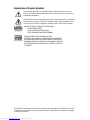
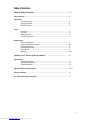
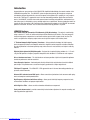
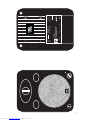
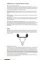
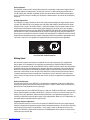
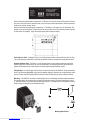
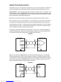
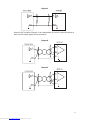
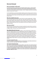
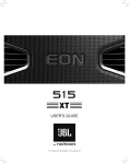
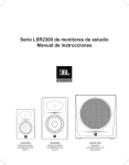
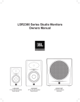
LSR6325P
Bi-Amplified Studio Monitor System
Owner’s Manual
Downloaded from www.Manualslib.com manuals search engine
Important Safety Instructions
The IEC fuse symbol pictured at the left represents an approved, user replaceable fuse. When replacing a
fuse, make sure to replace with only the correct type and fuse rating.
1. Read lnstructions - Before operating your new JBL product, please read all safety and operating
instructions.
2. Keep these instructions - For future reference and troubleshooting purposes, retain these instructions.
3. Heed all warnings - All warnings in this user manual should be followed.
4. Follow Instructions - By following instructions presented in this guide, you should be able to quickly
enjoy an accurate and safe monitoring system.
5. Water and Moisture - Do not use this apparatus near water or plumbing fixtures.
6. Cleaning - Clean with a lint-free cloth - Do not use any solvent based cleaners on the finish. A slightly
damp cloth can also be used on the enclosure surfaces and woofer surrounds.
7. Ventilation - Do not block any ventilation opening, including the Linear Dynamics Aperture Port on the
monitor systems. Install these products in accordance with manufacturers instructions. Do not install near
any heat sources such as radiators, heat registers, stoves or other apparatus that produce heat.
8. Grounding and Power Cords - The power cord supplied with your powered product has a 3-pin plug.
Do not cut off or damage the grounding pin. If the provided plug does not fit into your outlet, consult an
electrician for replacement of the obsolete outlet. Dress the power cords so that they will not be inadvertently
walked on or pinched, particularly at plugs, convenience receptacles and the points where they exit the apparatus.
All powered products are fitted with a detachable power cord (supplied) which connects to the chassis AC
connector. The power cord has an IEC female connector on one end and a male mains connector on the other
end. This cord is supplied specifically to accommodate the different safety and electrical code requirements
of individual countries. If you are traveling abroad with your system, test the power mains and be aware of
any specific voltage requirements before operating your system.
9. Options - Only use attachments or accessories specified by the manufacturer.
10. Non-use Periods - Unplug this apparatus during lightning storms or when it will be unused for long
periods of time.
11. Servicing - Refer all servicing to qualified service personnel. Servicing is required when the apparatus
does not work, or has been damaged in any way, including: damage to power cord or plug, water or other
liquid damage to the electronics, or damage due to falling or dropping.
12. Wall or Ceiling Mounting - The appliance should be mounted on a wall or ceiling only as recommended by the manufacturer. [See Pages 6 – 7]
13. Carts and Stands - The appliance should be used only with carts or stands that are sturdy and well
balanced. All appliance and cart combinations should be moved with care. Quick stops, excessive force, and
uneven surfaces may cause the appliance and cart combination to overturn.
2
Downloaded from www.Manualslib.com manuals search engine
Explanation of Graphic Symbols
The exclamation point within an equilateral triangle is intended to alert the user to the
presence of important operating and maintenance (servicing) instructions in the literature
accompanying the product.
The lightning flash with the arrowhead symbol, within an equilateral triangle, is intended to
alert the user to the presence of insulated ‘’dangerous voltage” within the product’s enclosure that may be of sufficient magnitude to constitute a risk of electric shock to persons.
CAUTION: TO REDUCE THE RISK OF ELECTRIC SHOCK
DO NOT REMOVE COVER.
NO USER SERVICEABLE PARTS INSIDE.
REFER SERVICING TO QUALIFIED PERSONNEL.
ATTENTlON: POUR EVITER LES RISQUES DE CHOC
ELECTRIQUE, NE PAS ENLEVER LE COUVERCLE. AUCUN ENTRETIEN
DE PIECES INTERRIEURES PAR L’USAGER. CONFIER L’ENTRETIEN AU
PERSONNEL QUALIFIE. AVIS: POUR EVITER LES RISQUES D’INCENDIE
OU D’ELECTROCUTION, N’EXPOSEZ PAS CET ARTICLE A LA PLUIE OU
A L’HUMIDITE.
The information contained in this document is confidential and the copyright of JBL Professional. To convey
its contents, in part of it whole, to any party without prior written authorization is a violation of the copyright.
© JBL Professional 2004
Downloaded from www.Manualslib.com manuals search engine
3
Table of Contents
Important Safety Instructions ................................................................................... 2-3
Table of Contents ........................................................................................................................ 4
Introduction
Front Panel Drawing ................................................................................................... 5
Rear Panel Drawing ................................................................................................... 6
LSR 6325 Features .................................................................................................... 5
Set-Up
Unpacking .................................................................................................................. 7
Placement .................................................................................................................. 6
Audio Connections ..................................................................................................... 7
AC Power Connections ............................................................................................... 7
Making Sound
Audio Level Adjustment .............................................................................................. 7
Frequency Response Adjustment ................................................................................ 8-9
80 Hz High Pass Filter ................................................................................................ 9
Boundary Compensation ............................................................................................ 9
LED Indication ............................................................................................................ 9
Mounting ................................................................................................................... 9-10
LSR6325P Systems with the LSR 6312SP Subwoofer ............................................................... 10
Specifications
System Specifications ................................................................................................ 11
Transducer Specifications .......................................................................................... 12
Performance Graphs .................................................................................................. 13
Appendix: Wiring Recommendations ......................................................................................... 14-15
Warranty Statement ................................................................................................................... 16
JBL Professional Contact Information ....................................................................................... 17
4
Downloaded from www.Manualslib.com manuals search engine
Introduction
Congratulations on your purchase of the LSR6325P Bi-Amplified Studio Monitor, the newest member of the
LSR6300 Series product line. The LSR6325P system incorporates patented JBL transducer and system
technologies designed to provide ultra-accurate response and exceptional SPL capability in a very compact
form-factor. THX® pm3™ approved for use in the most demanding production applications and environments, the LSR6325P is ideal for stereo and surround sound recording, post production, and broadcast systems where space is limited but accuracy and high-output are a requirement. Because production rooms are
acoustically less-than-perfect, JBL Professional has incorporated technologies in the LSR6325P to overcome
problems in the room. The result: clear accurate sound at the listening position in any room.
LSR6325 Features
5.25” Woofer with JBL Symmetrical Field Geometry (SFG) ® technology – Excursion is maximized by
using a massive 1.5” drive coil, while maintaining excellent distortion characteristics. The heavy magnetic
structure keeps power compression to a minimum reducing spectral shift as power levels increase. The
result is exceptional low frequency output and accurate spectral response at all listening levels.
1” Titanium Composite High Frequency Transducer – Using patented technology, the high frequency
device incorporates titanium and composite materials to improve transient response and reduce distortion.
By reducing distortion in the lower operating range, where the ear is most sensitive, ear fatigue is radically
reduced.
Elliptical Oblate Spheroidal (EOS) Waveguide – Designed for a targeted listening window of +/- 15º vertically, the EOS provides a frequency response through the entire window of 1.5 dB from on-axis response.
Di-cast aluminum enclosure – The rigid aluminum enclosure provides a high-inertial ground for optimum
transducer performance and low resonance.
Linear Dynamics Aperture – Contoured ports virtually eliminate high-end turbulence found in traditional
port designs. This provides more accurate low frequency performance at higher output levels.
THX® pm3™ approved – The LSR6325P is THX approved for use in the most demanding production applications and environments
Balanced XLR and unbalanced RCA inputs – Allows connection of professional and consumer audio equipment and computer recording workstations.
High Frequency Adjustment with three settings – allows you to tailor high frequency response to taste,
environmental conditions and program requirements.
80 Hz High Pass Filter – allows use with sub woofers without bass management.
Front-panel volume control – provides conveniently located volume adjustment in computer recording and
table-top production applications.
5
Downloaded from www.Manualslib.com manuals search engine
6
Downloaded from www.Manualslib.com manuals search engine
����������������������
�����������������
������������������
�����������������������
��������������������������
���������������������������
������������
��������������������������
���������
��������
������������������������
�������������������
����������������
������������
��������
����������
����������
���������
������
�������������
�
�
���������������
������������������
����������
��������������������������
������������������
��������������������������
���������������������������
����������������
����������������������
����������������������
LSR6325P Features to Tackle the Problems in the Room
LSR – Linear Spatial Reference Technology
JBL Developed Linear Spatial Reference Technology to optimize mid and high frequency accuracy at the
listening position where reflected sound comes into play. Meeting frequency response criteria for seventy-two
off-axis measurements, the LSR6325P ensures that not just the direct sound, but the reflected sound that
reaches you at the listening position is also smooth and accurate.
Boundary Compensation - A Boundary Compensation switch restores accurate bass response when the
loudspeaker is wall mounted, positioned close to walls, corners, placed on work surfaces or console meter
bridge.
Magnetic Shielding – The LSR6325P is magnetically shielded to allow use in close proximity to CRT video
and computer displays.
Mounting Options – The LSR6325P enclosure includes mounting points to provide flexibility and allow you to
optimize placement, particularly in small environments. Mounting points are compatible with industry-standard mounting hardware.
Optional LSR6312SP Subwoofer with Room Mode Correction - The use of an optional LSR6312SP
powered subwoofer in your LSR6325P system adds the powerful benefit of Room Mode Correction. The RMC
circuit in the LSR6312SP and the included RMC Calibration Kit allow you to identify and compensate for
troublesome low frequency standing waves. The result is clear extended bass response at the mix position in
any size room.
Set Up
Unpacking – Caution: The high-frequency transducer is unprotected and can be damaged if touched while
unpacking the speaker. An easy way to safely unpack your monitors is to open the top of the box, keep the
filler piece on and roll the box upside down. The box can then be slipped off. This also works in reverse for
repacking the system.
������
������
������
Placement – Speaker Placement
Listening Distance: In a stereo close-field application the speaker is typically placed 1 to 1.5 meters (3-5 feet)
from the listening position. In mid-field or surround sound applications, 2-3 meters is typical. The field in a
stereo listening application is optimized by arranging the speakers to form an equilateral triangle where the
distance between the two speakers equals the distance of each speaker to the listening position. Vertical vs.
Horizontal Placement: The LSR6325P system is designed for vertical orientation which provides broad lateral
dispersion and controlled vertical dispersion to optimize the size of the listening window and minimize reflections off the work surface and the ceiling. Horizontal placement will limit the size of the listening window and
increase reflections which can result in cancellation at high frequencies.
Angling towards the listening position: The LSR6325P should be angled so the center of the high frequency
transducer points directly at the listener’s ears.
7
Downloaded from www.Manualslib.com manuals search engine
Audio Connections
The LSR6325P includes one XLR and one RCA connector to accommodate a wide range of signal levels and
balanced or unbalanced configurations. The XLR input is nominal +4 dBu sensitivity and the RCA input is
-10 dBV. Variable user calibration is provided using the front panel volume control. Positive voltage applied
to pin 2 of the XLR or the pin of the RCA jack will produce a forward motion in the cone of the low frequency
transducer.
AC Power Connections
The LSR6325P has a power transformer which allow it to be used with multiple AC supply voltages around
the world. The LSR6325P will accept voltages from 100-120 or 200-240 Volts, 50-60 Hz when the voltage
setting and fuse is correct. The rating is visible in a small white window on the fuse holder. Before connecting the system to the AC power, confirm that the switch setting on the rear of the unit is set to the proper
position and the fuse is the correct rating. (WHAT IS THE CORRECT FUSE VALUE FOR 110 AND 220? HOW DO
YOU REPLACE THE FUSE) The ground terminal of the IEC plug is required by wiring codes and regulations. It
must always be connected to the electrical installation and safety ground. The LSR6325P units have carefully
designed internal grounding and balanced inputs and outputs to reduce the possibility of ground loops which
cause hum. If hum occurs, see Appendix A for suggested audio signal wiring and system grounding.
Rear Panel XLR and RCA Connectors
Making Sound
After the audio and power connections are completed, the next step is to power-up. It is recommended
that you power all the equipment in the system prior to powering up the amplified LSR6325P monitors.
Alternately, if the speakers are ON, set the LSR6325P volume controls to their full counter clock-wise position
to produce minimum gain when powering up or powering down other components in the system. When the
Green LED on the front panel is illuminated, the speaker system is ready to go. Slowly advance gain of the
sound source and/or slowly increase the gain of the LSR6325P by turning the front panel volume control in
a clockwise direction and check for system noise. If everything is correct, advance the level of the sound
source, sit back and enjoy. If there is excessive hum, noise or no signal, see Appendix A for suggested wiring
practices.
Audio Level Adjustment
The audio level sensitivity of the LSR6325P can be adjusted to accommodate a wide range of applications.
Audio systems typically send signal with nominal level of either +4 dBu or -10 dBV. These are referred to as
professional and semi professional levels, respectively.
The nominal input level of the LSR6325P XLR input is +4 dBu and -10 dBV for the RCA input. A nominal level
to these inputs will produce an output of 96 dB SPL at a distance of 1 meter in an anechoic environment. This
allow the user to get a good match when using either professional or semi professional equipment. If less
sensitivity is needed the front panel volume control can be adjusted down. When set in the 12:00 position, the
front panel volume control attenuates the signal by 9 dB.
Frequency Response Adjustments
Four DIP switches located in a recess on the rear-panel of the LSR6325P allow the user to adjust frequency
response to compensate for placement, program material and personal preference. To activate the associated
switch function, set the switch in the UP position – so the switch is closer the JBL logo on the rear of the
speaker. The LSR6325P is shipped with all switches in the DOWN position so the switches are at the setting
farthest away from the JBL logo.
8
Downloaded from www.Manualslib.com manuals search engine
����������������
��������
����������
����������
���������
������
�������������
����������������������
�����������������
������������������
�����������������������
��������������������������
���������������������������
Switch 3 boosts the high frequency response by 1.5 dB above 2.3 kHz when set to the UP position. This position can be used if the room is extremely dead, or you want to hear more high frequency from the speaker to
assist you in creating “warmer” mixes.
Switch 4 attenuates the high frequency response by 1.5 dB above 2.3 kHz when set in the UP position. This
position can be used if the room is highly reflective or you want to hear less high frequency from the speaker
to allow you to mix “brighter,” apply more high frequency EQ or signal processing.
80 Hz High Pass Filter – Setting DIP switch 1 in the UP position activates a 80 Hz High-Pass filter. This filter
can be activated when LSR6325P is used with sub woofers that do not include bass management features.
Boundary Compensation – DIP Switch 2 can be used to restore accurate system performance when the
speaker is placed on a work-surface, or near wall or boundary. The setting is particularly useful when the
speaker will be positioned on a table-top and used with computer audio production system.
LED Indication – A single bi-color LED indicator is located on the front of the LSR6325P. In normal operation,
the LED will be illuminated GREEN. At the onset of amplifier clipping in either the low or high frequency amplifier, the LED will flash RED. Continual RED illumination of this LED indicates that levels should be reduced.
Mounting – The LSR6325P has built-in mounting points for use with industry-standard mounting hardware.
The mounting points are located on the rear panel of the speaker system. The four threaded holes accept a
¼” diameter machine screw with a pitch of 20 threads per inch. The length of the screw should be a total of
5/8th inch plus the thickness of the mounting bracket.
Mounting Hole Pattern
Downloaded from www.Manualslib.com manuals search engine
9
Caution: Unsafe mounting or overhead suspension of any heavy load can result in serious injury and equipment damage. Mounting of speakers should be done by qualified persons in accordance with all applicable
local safety and construction standards. Be certain to follow the instructions provided by the manufacturer of
the mounting bracket. Be certain that it is capable of supporting the weight of the speaker to be mounted.
LSR6325P Systems with the LSR6312SP Subwoofer
The addition of the LSR6312SP Subwoofer provides an exceptionally accurate system with bass extension
to 26 Hz, even greater SPL capability, and the extra benefit of JBL RMC™ Room Mode Correction. RMC is an
electronic system designed by JBL Professional and built into the subwoofer, which corrects low frequency
inaccuracies caused by room modes or standing waves in the listening environment. For more information
about RMC, visit the JBL Professional Web site at www.jblpro.com/LSR. Two system examples follow.
�����
���
���
����
����
����
�����
������
�����
���������
Stereo System
������
�����
����
���
���
���
����
����
����
�����
�����
������
�����
�������������
������
������
���������
�����
�����
���������
����������
5.1 Surround System
Note: LSR6325P 80 Hz High Pass Filter is OFF
10
Downloaded from www.Manualslib.com manuals search engine
Specifications
System:
Frequency Response (+1, -2 dB):
70 Hz – 20 kHz
Enclosure Resonance Frequency:
55 Hz
Low Frequency Extension:
User controls set to default
-3 dB:
65 Hz
-6 dB:
56 Hz
-10 dB:
48 Hz
Low – High Frequency Crossover:
2.3 kHz
4th – Order Electroacoustic Linkwitz – Riley
Distortion, 96 dB SPL, 1 m:
Mid – High Frequency (150 Hz – 20 kHz):
2nd Harmonic:
<0.5%
3rd Harmonic:
<0.5%
Low Frequency (<150 Hz:
2nd Harmonic:
<2%
3rd Harmonic:
<3%
Maximum SPL (90 Hz – 20 kHz):
>106 dB SPL / 1 m
Maximum Peak SPL (90 Hz – 20 kHz):
>109 dB SPL / 1 m
Signal Input:
XLR, Balanced
RCA, Unbalanced
Passive voltage applied to XLR Pin 2 (RCA tip) produces
outward woofer motion.
Calibrated Input Sensitivity:
XLR,+4 dBu:
96 dB/1 m
RCA, -10 dBV:
96 dB/1 m
Self Generated Noise Level:
AC Input Voltage:
AC Input Voltage Operating Range:
AC Input Connector:
<10 dBA SPL/1 m
115/230 VAC, 50/60 Hz (User Selectable)
+/- 15%
IEC
User Controls:
High Frequency Control (3 kHz – 20 kHz):
Workstation Boundary Compensation:
Low Frequency Alignment:
+1.5 dB, 0 dB, -1.5 dB
Active & Bypass
36 dB/Octive Butterworth high-pass at 40 Hz
36 dB/Octive Bessel high-pass at 40 Hz
(for use with subwoofer)
Variable Input Attenuation:
0 – 26 dB (9 dB at 12 o’clock)
Amplifiers:
Low Frequency:
Topology:
Sine Wave Power Rating:
Bridged Class A–B Monolithic
100 Watts (<0.1% THD into rated impedance)
11
Downloaded from www.Manualslib.com manuals search engine
THD+N, 1/2 power: <0.05%
High Frequency:
Topology: Class A-B, Monolithic
Sine Wave Power Rating: 50 watts (<0.1% THD into rated impedance)
THD+1/2 power: <0.05%
Long Term Maximum System Power: 110 Watts (IEC 265-5)
Transducers:
Low Frequency Diameter: 134 mm (5.25 in.)
Voice Coil: 38 mm (1.5 in.)
Magnet Type: Ferrite with Integral Shielding
Cone Type: Tempered Paper with Buty Rubber Surround
Nominal Impedance: 8 ohm
High Frequency Diameter: 25 mm (1 in.) diaphragm
Voice Coil: 25 mm (1 in.)
Magnet Type: Ferrite with Integral Shielding
Diaphragm Type: Damped Titanium Composite
Other Features: Elliptical Oblate Spheroidal Waveguide
Nominal Impedance: 4 ohms
Physical:
Finish: Smooth Dark Graphite
Grille: Black Steel Perforated
Enclosure Volume (net): 6.5 cu. liter (0.2 cu. ft.)
Low Frequency Vent: Dual Front Ported Linear Dynamics Aperture (Integrated with die-cast baffle)
Baffle Construction: Integrated with Die-Cast Aluminium
Cabinet Construction: Integrated with Die-Cast Aluminium
Net Weight: 7.7 kg (17 lbs..)
Dimensions (W x H x D): 17.3 x 26.9 x 24.1 cm
(6.8 x 10.6 x 9.5 in.)
Notes:
All measurements unless otherwise stated made anechoically in a 4 environment at 2 meters and referenced to 1 meter by the
inverse square law.
The reference measurement microphone position is located perpendicular to the center line of the low and high frequency transducers, at the point 70 mm (2.7 in.) above the center of the woofer.
Acoustic loading provided by the listening room increases Maximum SPL capabilities and low frequency bass Extension as
compared to standard anechoic values.
Distortion measurements performed with the input voltage necessary to produce the stated “A” weighted SPL level at the stated
measurement distance. Distortion figures refer to the maximum distortion measured in any 1/10th octave wide band in the stated
frequency range.
JBL continually engages in research related to product improvement. New materials, production methods and design refinements
are introduced into existing products without notice as a routine expression of that philosophy. For this reason, any current JBL
product may differ in some respect from its published description, but will always equal or exceed the original design specifications
unless otherwise stated.
12
Downloaded from www.Manualslib.com manuals search engine
�������������������
200
100
100
-100
SPL
Phase
0
90
-200
80
-400
-300
dB
-500
-600
-700
70
-800
-900
60
20
100
Frequency
1000
Hz
-1000
10000
20K
����������������������
������������
������������
������������������������
�������������������
������������������������������
����������������������� ��������
������������� ��������
������������������������������
�����������������������������
�������������������������
�������������������������
13
Downloaded from www.Manualslib.com manuals search engine
Appendix: Wiring Recommendations
For optimum performance, some attention to wiring details can reduce system degradation. If you notice hum
present in the system when no audio signal is present, the following wiring recommendations can help.
Balanced Sources – The best way to run your system is balanced, where both “HOT” (+) and “COLD” (-) signals are supplied, as well as a GROUND/SHIELD. These are typically carried on two conductor shielded cables
with XLR connectors on both ends. Whenever possible, the cable shield should not be connected to any signal
pin, but left to perform a cable shielding function only.
Note: Under no circumstances should the safety ground wire be removed from the AC power connector.
When using balanced sources with the LSR6325P, it is recommended to use the XLR input on the LSR6325P.
This maintains a balanced signal and is the best way to reduce the possibility of hum or other interference.
For balanced sources, the “HOT” (+) signal from your source should be connected to Pin 2 of the XLR input as
shown in Diagram A. The “COLD” (-) signal should be connected to Pin 3 of the XLR. To avoid ground loops,
connect the SHIELD at the source end but not at the LSR input.
The LSR6325P was designed to output a level of 96 dB SPL at 1 meter with a +4 dBu signal applied to the
XLR input. If additional gain is required from a balanced output, Diagram B can be used with the RCA input.
The sensitivity of the RCA input is approximately 12 dB higher than the XLR input.
Diagram A
While there are only HOT and GROUND/SHIELD connections from unbalanced sources, it is recommended
that high quality twisted pair cable be used when using the XLR input of the LSR6325P. Diagram D shows
an unbalanced source connected to the balanced XLR input of the LSR monitor using twisted pair cable. Note
that the shield is connected to the GROUND/SHIELD connector at the LSR input, but not at the source. This
reduces the likelihood of introducing a ground loop into the system.
Diagram B
14
Downloaded from www.Manualslib.com manuals search engine
Diagram C
Diagram D and E are similar. In Diagram E, a link is added between Pin 3 and Pin 2 of the XLR connector. In
some cases, this could be required if hum is encountered.
Diagram D
Diagram E
15
Downloaded from www.Manualslib.com manuals search engine
Warranty Statement
Who Is Protected by This Warranty?
Your JBL Warranty protects the original owner and all subsequent owners so long as: A.) Your JBL product
has been purchased in the Continental United States, Hawaii or Alaska. (This Warranty does not apply to
JBL products purchased elsewhere except for purchases through military outlets. Other purchasers should
contact the local JBL distributor for warranty information.); and B.) The original dated bill of sale is presented
whenever warranty service is required.
The JBL Limited Warranty on professional loudspeaker products (except for enclosures) remains in effect for
five years from the date of the first consumer purchase. JBL amplifiers are warranted for three years from the
date of original purchase. Enclosures and all other JBL products are warranted for two years from the date of
original purchase.
What does the JBL Warranty cover?
Except as specified below, your JBL Warranty covers all defects in material and workmanship. The following are not covered: Damage caused by accident, misuse, abuse, product modification or neglect; damage
occurring during shipment; damage resulting from failure to follow instructions contained in your Instruction
Manual; damage resulting from the performance of repairs by someone not authorized by JBL; claims based
upon any misrepresentations by the seller; any JBL product on which the serial number has been defaced,
modified or removed.
Who Pays for What?
JBL will pay all labor and material expenses for all repairs covered by this warranty. Please be sure to save
the original shipping cartons because a charge will be made if replacement cartons are requested. Payment
of shipping charges is discussed in the next section of this warranty.
How to Obtain Warranty Performance?
If your JBL product ever needs service, write or telephone us at JBL Incorporated (Attn.: Customer Service
Department), 8500 Balboa Boulevard, PO. Box 2200, Northridge, California 91329 (800/852-5776). We may
direct you to an authorized JBL Service Agency or ask you to send your unit to the factory for repair. Either
way, you’ll need to present the original bill of sale to establish the date of purchase. Please do not ship your
JBL product to the factory without prior authorization. If transportation of your JBL product presents any
unusual difficulties, please advise us and we may make special arrangements with you. Otherwise, you are
responsible for transporting your product for repair or arranging for its transportation and for payment of
any initial shipping charges. However, we will pay the return shipping charges if repairs are covered by the
warranty.
Limitation of Implied Warranties
ALL IMPLIED WARRANTIES, INCLUDING WARRANTIES OF MERCHANTABILITY AND FITNESS FOR PARTICULAR
PURPOSE, ARE LIMITED IN DURATION TO THE LENGTH OF THIS WARRANTY.
EXCLUSION OF CERTAIN DAMAGES
JBL’S LIABILITY IS LIMITED TO THE REPAIR OR REPLACEMENT, AT OUR OPTION, OF ANY DEFECTIVE PRODUCT
AND SHALL NOT INCLUDE INCIDENTAL OR CONSEQUENTIAL DAMAGES OF ANY KIND. SOME STATES DO NOT
ALLOW LIMITATIONS ON HOW LONG AN IMPLIED WARRANTY LASTS AND/OR DO NOT ALLOW THE EXCLUSION
OF INCIDENTAL OR CONSEQUENTIAL DAMAGES, SO THE ABOVE LIMITATIONS AND EXCLUSIONS MAY NOT APPLY TO YOU. THIS WARRANTY GIVES YOU SPECIFIC LEGAL RIGHTS, AND YOU MAY ALSO HAVE OTHER RIGHTS,
WHICH VARY, FROM STATE TO STATE.
16
Downloaded from www.Manualslib.com manuals search engine
JBL Professional Contact Information
Mailing Address:
JBL Professional
8500 Balboa Blvd.
Northridge, CA 91329
Outside the U.S.A.
Contact the JBL Professional Distributor in your area. A
complete list of JBL Professional International Distributors
is provided at our U.S.A. web site - www.jblpro.com
Shipping Address:
JBL Professional
8370 Balboa Blvd., Dock D
Northridge, CA 91329
En Dehors des Etats-Unis:
Contacter votre Distributeur JBL Professional. Une liste
complète de nos distributeurs internationaux est disponible sur le site web - www.jblpro.com.
Customer Service:
Monday through Friday
8:00am - 5:00pm
Pacific Coast Time in the U.S.A.
(800) 8JBLPRO (800.852.5776)
www.jblproservice.com
International:
Wenden Sie sich an lhre örtiche JBL Professional Vertretung. Eine vollstandige Liste der internationalen. JBL
- Vertretungen finfen Sie auf userem Web site unter www.
jblpro.com.
On the World Wide Web:
www.jblpro.com
Fuera de los Estados Unidos:
Comuníquese con el distribuidor de JBL Professional de su
zona. En nuestro sitio web, www.jblpro.com, encontrará
una lista completa de los distribuidores de JBL International.
Product Registration:
Register your product online at
www.jblpro.com/registration
17
Downloaded from www.Manualslib.com manuals search engine
JBL Professional
8500 Balboa Boulevard
P.O.Box 2200
Northridge, California 91329
U.S.A.
www.jblpro.com
Downloaded from www.Manualslib.com manuals search engine
LSR6325P Manual
98100056-00
CRP 1M
6/04