1
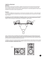
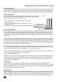
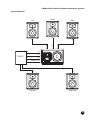
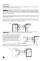
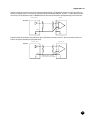
LSR6300 Studio Monitors
Owner’s Manual
Important Safety Instructions
1. Read These Instructions - Before operating your new JBL product,
please read safety and operating instructions.
Explanation of Graphic Symbols
2. Keep These Instructions - For future reference and troubleshooting
purposes, retain these instructions.
The exclamation point within an equilateral triangle is
intended to alert the users to the presence of important operating and maintenance (servicing) instructions in the literature accompanying the product.
3. Heed All Warnings - All warnings in this manual should be followed.
4. Follow All Instructions
5. Water and Moisture - This product is intended for indoor use only. Do
not use this apparatus near water or plumbing fixtures.
The lightning flash with the arrowhead symbol, within an equilateral triangle, is to alert the user to the
presence of insulated “dangerous voltage” within the
products enclosure that may be of sufficient magnitude to constitute a risk of electric shock to humans.
6. Cleaning - Do not use any solvent based cleaners on the finish. To
clean enclosure, turn off speaker and disconnect power cord then
clean only with a lint-free cloth moistened with water.
7. Ventilation - Do not block any ventilation openings, including the Linear
Dynamics Aperture Port on the monitor systems. Install these products in
accordance with manufacturers instructions. Do not install near any
heat sources such as radiators, heat registers, stoves or other
apparatus that produce heat.
8. Grounding and Power Cords - Protect the power cord from being
walked-on or pinched, particularly at the plug’s convenience recepticle and the point where it connects to the apparatus. Do not defeat
the safety purpose of the grounding type plug. The power cord supplied with your powered product has a plug with 2 blades plus a 3rd
grounding prong. Do not cut off or damage the grounding prong. If the
provided plug does not fit into your outlet, consult an electrician for
replacement of the obsolete outlet.
All powered products are fitted with a detachable power cord
(supplied) which connects to the chassis AC connector. The power
cord has an IEC female connector on one end and a male mains connector on the other end. This cord is supplied specifically to accommodate the different safety and electrical code requirements of individual countries. If you are traveling abroad with your system, test the
power mains and be aware of any specific voltage requirements
before operating your system.
CAUTION
RISK OF ELECTRIC SHOCK
DO NOT OPEN!
DO NOT EXPOSE
TO RAIN OR MOISTURE!
ATTENTION
RISQUE DE CHOC ÉLECTRIQUE
NE PAS ENLEVER!
NE PAS EXPOSER Á
LA PLUIE NI Á L'HUMIDITÉ!
CAUTION: TO REDUCE THE RISK OF ELECTRONIC
SHOCK - DO NOT REMOVE COVER. NO USER SERVICEABLE PARTS INSIDE. REFER SERVICING TO
QUALIFIED PERSONNEL. DO NOT EXPOSE THIS APPARATUS TO RAIN OR MOISTURE.
ATTENTION: POUR EVITER LES RISQUES DE CHOC
ELECTRIQUE, NE PAS ENLEVER LE COUVERCLE.
AUCUN ENTRETIEN DE PIECES INTERIEURES PAR
L’USAGER. CONFIER L’ENTRETIEN AU PERSONNEL
QUALIFIE. AVIS: POUR EVITER LES RISQUES D’INCENDIE OU D’ELECTROCUTION, N’EXPOSEZ PAS CET
ARTICLE A LA PLUIE OU A L’HUMIDITE.
9. Options - Only use attachments or accessories specified by JBL
Professional.
10. Wall or Ceiling Mounting - The appliance should be mounted on a
wall or ceiling only as recommended by the manufacturer. Caution:
Unsafe mounting or overhead suspension of any heavy load can result
in serious injury and equipment damage. Mounting of speakers should
be done by qualified persons in accordance with all applicable local
safety and construction standards. Be certain to follow the instructions
provided by the manufacturer of the mounting bracket. Before selecting a mounting bracket, be certain that it is capable of supporting the
weight of the speaker to be mounted.
11. Non-use Periods - Unplug this apparatus during lightning storms or
when it will be unused for long periods of time.
12. Servicing - Refer all servicing to qualified service personnel. Servicing
is required when the apparatus does not operate normally or has been
damaged in any way, including: power supply cord or plug is damaged, water or other liquid has been spilled or objects have fallen into
the apparatus.
13. Carts and Stands - The appliance should be used
only with carts or stands that are sturdy and well
balanced. All appliance and cart combinations
should be moved with care. Quick stops, excessive
force, and uneven surfaces may cause the appliance
and cart combination to overturn.
14. Fire - No naked flame sources, such as lighted candles, should be
placed on the surface, of the apparatus.
15. Coupler - The appliance coupler is used as the disconnect device, and
the appliance coupler shall remain readily operable.
2
The information contained in this document is confidential and the
copyright of JBL Professional. To convey its contents, in part of it
whole, to any party without prior written authorization is a violation of
the copyright. © JBL Professional 2003
Table Of Contents
Introduction
4
Getting Started
Unpacking
Placement
Power Connections
Making Sound
5
LSR6328P Biamplified Studio Monitor System
Audio Connections
AC Power Connections
Audio Level Adjustment
Low Frequency Adjustment
High Frequency Adjustment
LED Indication
RMC Equalization
5
5
6
6
7-9
7
8
8
8
9
9
9
LSR6332 Studio Monitor System
Audio Connections
High Frequency Adjustment
Changing Mid/High Orientation
10 - 11
LSR6312SP Powered Studio Subwoofer System
Audio Connections
AC Power Connections
Audio Level Adjustment
Low Frequency Adjustment
LED Indication
RMC Equalization
System Configuration
12 - 15
Appendix
A. Wiring Requirements
B. Mounting Specifications
C. RMC™ Room Mode Correction System Specifications
16 - 18
Specifications
LSR6328P
LSR6332
LSR6312SP
19 - 21
10
10
11
12
13-14
14
14
14
14
15
16 - 17
18
18
19
20
21
Warranty Statement
23
JBL Professional Contact Information
24
3
Introduction
Congratulation on your purchase of LSR6300 Studio Monitors. All LSR6300 models incorporate proprietary and patented JBL transducer
and network technologies., to provide ultra-accurate response, and exceptional SPL capability. Because production rooms are acoustically less-than-perfect, JBL has incoporated technologies in the LSR6300 Studio Monitors to overcome problems in the room. The
result: clear accurate sound at the listening position in any room.
LSR6300 Features to Overcome the Problems in the Room
LSR - Linear Spatial Reference Technology
JBL developed Linear Spatial Reference Technology to improve mid and high frequency accuracy at the listening position where reflected sound comes into play. By meeting frequency response criteria for seventy-two off-axis measurements, the LSR6300 Studio
Monitors ensure that not just the direct sound, but the reflected sound that reaches you at the listening position is also smooth and
accurate.
RMC™ - Room Mode Correction
The LSR6328P and LSR6312SP Subwoofer are equipped with RMC - JBL’s method of zeroing out bass problems at the listening position caused by room modes. The LSR6332 Studio Monitor and other speakers enjoy the benefits of RMC when used in a system with
the LSR6312SP Subwoofer. The RMC Calibration Kit* gives you everything you need to tune your LSR system and compensate for the
room modes in the listening environment.
*Included with the LSR6312SP, Optional accessory for the LSR6328P
Boundary Compensation
LSR6328P and LSR6312SP boundary compensation presets restore accurate bass response when the loudspeakers are wall mounted
or positioned close to walls, corners and placed on work surfaces.
Mounting Options
LSR6300 enclosures are reinforced to make them safe for mounting and mounting points are provided for use with readily available,
industry-standard mounting brackets.
THX® pm3™
All LSR6300 models are THX® pm3™ approved for use in the most demanding production applications and environments.
JBL Transducer Technologies
Differential Drive®
New voice coils and motor assemblies have two separate drive coils with twice the thermal surface area of traditional speakers. This
enables LSR6300 systems to provide higher peak output with less power compression, greater heat dissipation and a flatter impedance
curve at higher frequencies. By reducing the thermal related effects, the LSR6300 Studio Monitors sound the same at low, medium or
high levels.
Linear Dynamics Aperture™
Contoured ports virtually eliminate high-end turbulence found in traditional port designs. This provides more accurate low frequency
performance at higher output levels.
Dynamic Braking
All LSR6300 low frequency transducers are equipped with an electromagnetic braking voice coil to reduce the effects of extreme excursion with high transient program materials.
Titanium Composite High-Frequency Device
Using patented technology, the high frequency device incorporates titanium and composite materials to improve transient response and
reduce distortion. By reducing distortion in the lower operating range, where the ear is most sensitive, ear fatigue is radically reduced.
Elliptical Oblate Spheroidal (EOS) Waveguide
Designed for a targeted listening window of ±30º horizontally and ±15º vertically, the EOS waveguide provides a frequency response
through the entire window of 1.5 dB from on-axis response. This allows listeners at a distance from the speakers and even far off-axis
to hear an accurate representation of the on-axis response.
Neodymium Midrange with Kevlar™ Cone
A 2” neodymium motor structure is used in the LSR6332 for high excursion capability with an intentionally low crossover point of 250
Hz. This improves the spatial response of the system, which is crucial for accurate reproduction.
4
Getting Started
Unpacking:
When removing the systems from their packaging, it is important not to grasp the units from the front. Because the high frequency
device is located near the top of the cabinet on the front baffle, a stray hand or finger can cause damage. The best way to safely
unpack your monitors is to open the top of the box, keep the cardboard filler piece on, and roll the box upside down. The box can then
be slipped off. This also works in reverse for repacking the units.
Placement:
The design of the LSR6300 systems lend themselves to a wide variety of placement options. Covered here is a typical stereo setup for
near to mid field monitoring. A more detailed discussion of multi-channel sound system placement is available from JBL in Tech Note
Volume 3, Number 3.
Listening Distance: The common listening position at mixing postions is generally 1 to 1.5 meters (3 to 5 feet) for near field applications.
For mid-field applications, 2 to 3 meters is more likely. The stereo listening angle is largely a matter of personal preference, and we
suggest the angle of the loudspeakers should be between 35 and 50 degrees, as shown in Figure A.
Figure A
35-50˚
35-50˚
35-50˚
Vertical vs. Horizontal Placement: The LSR6328P model is designed to be positioned vertically. This orientation eliminates the phase
shifts that occur when the relative distances between the woofer, tweeter and the listening position are altered. The high frequency
waveguide is designed to provide optimum dispersion when the system is placed vertically. Placing the system horizontally will defeat
the LSR principles and cause destructive reflection off the work surface.
The LSR6332 is normally used in the horizontal position. This provides the lowest elevation to maximize sight lines and reduce shadowing of soffit mount monitors. In applications where vertical orientation is desired, the entire mid and high assembly can be rotated 90°
to a vertical line array position, as shown below in Figure B:
Figure B
5
Getting Started
The LSR6312SP can be placed in either a vertical or horizontal orientation. More important than orientation is the physical position in
the room.
Angling toward the listening position: The LSR6300-Series monitors should be angled to directly face the listener. The center of the high
frequency transducer should be on-axis with the ear level of the listener. Ideally, full-range speakers should be placed on suitable
speaker stands away from boundaries. The LSR6312SP Subwoofer can be located on the floor with its woofer cone on the same plane
as the woofer cones of the full-range speakers. Alternately, the Subwoofer performance can benefit from placement close to a wall or
corner. LSR6328P and LSR6312SP models include Boundary Compensation settings when speakers are placed in close proximity to
walls, corners and work surfaces.
Audio Connections
Refer to individual model-specific instructions.
Power Connections
The LSR6328P can be used with multiple AC supply voltages around the world. It will automatically adjust for operation from 100 to
240 VAC with no intervention by the user. The ground terminal of the IEC plug is required by wiring codes and regulations. It must
always be connected to the electrical installation safety ground. The LSR6300-Series units have carefully designed internal grounding
and balanced inputs and outputs to reduce the possibility of ground loops (hum). If hum occurs, see Appendix B for suggested audio
signal wiring, system grounding hints and other preventive measures. The LSR6312SP is set at the factory for use with either 100V125V or 200V-250V. Voltage is not field selectable.
Making Sound
After connections are made, the next step is to power up all equipment before powering up active LSR6300 speakers and external
amplifiers. Reduce the level of the monitor outputs of your console or preamp to minimum and turn on the powered speakers and the
amplifiers. There is a small delay with the power-up of the LSR6328P and LSR6312SP to accommodate for clicks and thumps from
upstream equipment. When the Green LED on the front panel turns on, the units are ready to go. Slowly advance the gain of the console
to feed the monitoring system to suitable listening level, and enjoy.
Figure C
6
LSR6328P Biamplified Studio Monitor System
The LSR6328P Bi-amplified Studio Monitor sets the standard for exceptional performance in near field design.
With a combination of advanced transducer engineering and powerful drive electronics, the LSR6328P meets the
professional’s requirement for accuracy and high dynamic range on the most demanding sessions.
The addition of JBL RMC™ Room Mode Correction circuit and boundary compesnation ensures accurate low frequency response at the listening position, free of the spectral shift caused by room modes and the effect of
boundaries.
The 8" woofer is based on JBL's patented Differential Drive® technology. With dual 1.5" drive coils, power compression is kept to a
minimum to reduce spectral shift as power levels increase. An added third coil between the drive coils acts as a dynamic brake to limit
excess excursion and reduces audible distortion at maximum levels. The cone is made of a carbon fiber composite forming a rigid piston and is supported by a soft butyl rubber surround.
The high frequency device is a 1" composite diaphragm integrated with an Elliptical Oblate Spheroidal (EOS) Waveguide with 100° by
60° dispersion, which is critical to the smooth spatial response required in today's working environments. The magnetically sheilding of
the HF transducer reduces interference when used in close proximity to CRT video and computer monitors. This custom power supply
eliminates all tonal-artifacts produced by the speaker when idling.
Audio Connections
LSR6328P Audio Connections: The LSR6328P comes with a Neutrik "Combi" connector that accommodates either an XLR or 1/4" connector in either balanced or unbalanced configurations. The system has switchable input sensitivity: +4 dBu, +8 dBu, and -10 dBV.
These sensitivities are determined by adjusting the DIP switches according to the legend shown in Figure C. When the sensitivity is set
for, say, +4 dBu, an input signal equal to +4 dBu will produce a system output level of 96 dB SPL at a distance of one meter. Likewise,
settings of +8 dBu and -10 dBV will cause those input levels to attain the output acoustic level of 96 dB SPL.
An additional switch allows user-adjustable input sensitivity via a screwdriver control on the back panel. See Section 4 for additional
information on level control and gain matching. Positive voltage to Pin 2 of the XLR or the tip of the 1/4" jack will produce a forward
motion in the low frequency cone. Shown below in Figures C and D are views of the rear electronics panel on the LSR6328P and a signal flow diagram for the system. We recommend that you study these drawings in detail.
Figure D
7
LSR6328P Biamplified Studio Monitor System
AC Power Connections
The LSR6328P can accommodate power from 100 to 250 VAC 50/60 Hz by way of an autosensing power supply. This requires no attention on the part of the user.
The ground terminal of the IEC plug is required by wiring codes and regulations. It must always be connected to the electrical installation safety ground. The LSR6300 Series models have carefully designed internal grounding and balanced inputs and outputs to reduce
the possibility of ground loops (hum). If hum or buzz occur, see Appendix A for suggested correct audio signal wiring and system
grounding.
Audio Level Adjustment
The audio level sensitivity of the LSR6328P can be adjusted for almost any situation. Monitor outputs of consoles and work stations are
normally at a nominal level of +4 dBu or -10 dBV.
The LSR6328P can be set up for fixed or variable gain. As shipped from the factory, a nominal signal input of -10 dBV (0.3 volts) will
produce an output of 94 dB SPL at 1 meter in an anechoic environment. This allows the user to get a good match when using either
professional or semiprofessional equipment. Using the DIP switches on the back as shown below in Figure E, the system can be set for
+4 dBu, +8 dBu or +12 dBu sensitivity.
Switch 1 enables the Trim Control. With the switch in the down position, the Trim Control is out of the circuit and does not affect the
input sensitivity. In the up position, the input trim is added to the circuit and will attenuate the input level from 0 - 13 dB relative to
nominal.
• Switch 2 lowers the input sensitivity to +4 dBu sensitivity when in the up position.
• Switch 3 lowers the input sensitivity to +8 dBu sensitivity when in the up position.
• Switches 2 and 3 in the up position lower input sensitivity to +12 dBu.
Figure E
Low Frequency Adjustment
The low frequency response of the LSR6328P can be adjusted to increase or reduce the low frequency output level. With all bass
adjustment switches off, the unit is set to a 36 dB/octave roll-off with a maximally flat characteristic.
Switch 4 - VLF, Very Low Frequency Protect: Switch 4 changes the low frequency roll-off to a 24 dB/octave slope, which extends the low
frequency capability, while slightly reducing maximum sound pressure level. This is useful for spotting subsonic signals that could otherwise go undetected. For example, extreme low frequency rumble will be visible as a pronounced "fluttering" motion of the woofer cone.
To protect the low frequency transducer, normally switch 4 is set to Off.
8
LSR6328P Biamplified Studio Monitor System
Boundary Compensation
Switch 5 introduces a low frequency shelf roll-off of -1.5 dB, while Switch 6 introduces a low frequency shelf rolloff of -3 dB. Engaging
both switches will produce a low frequency shelf rolloff of -4.5 dB. These functions are known as Boundary Compensation and are used
to adjust for the build-up of low frequencies that accompany the placement of loudspeakers near walls or corners, or work surfaces.
The changes in low frequency response using Switches 4, 5, and 6 are shown in Figure F.
15.00
Amplitude (dBu)
Diagram F
0 dB
-1.5 dB
-3.0 dB
-4.5 dB
20.00
10.00
5.00
0.0
-5.00
-10.00
-15.00
-20.00
10
20
30 40 50
100
200
Frequency (Hz)
High Frequency Adjustments
Switch 7 introduces a high frequency response shelf cut of 1 dB above 2 kHz. This may be used if the room is fairly live, or if you are
fairly close to the loudspeakers. Switch 8 introduces a high frequency response shelf boost of 1 dB above 2 kHz. This may be used if
the room is extremely dead. The changes in high frequency response using Switches 7 and 8 are shown below in Figure G:
90
Switch 8 On +1 dB
Switch 7 & 8 Off Flat
Switch 7 On -1 dB
SPL (dB)
Figure G
80
70
60
10000
1000
Frequency (Hz)
LED Indication
A single LED indicator is located on the front of the LSR 6328P. In normal operation, this LED will be GREEN. At the onset of clipping in
either the low or high frequency amplifier, the LED will flash RED. Continuous flashing of the red LED indicates that levels should be
reduced. Caution: The LSR6328P is capable of producing extremely high sound pressure levels. To avoid hearing damage, caution
should be exercised.
RMC Equalization
There are three screwdriver adjustable controls on the rear panel of the 6328P indicated RMC. The term RMC stands for Room Mode
Correction, which consists of a single section cut-only parametric equalizer that can be adjusted in frequency, width (Q) of cut, and the
amount of cut. It is used to reduce the magnitude of any dominant low frequency peak in response due to standing waves at the listening position. Details of Room Mode Correction are presented in the user guide included with the RMC Calibration Kit.
9
LSR6332 Studio Monitor System
The LSR6332 Linear Spatial Reference Studio Monitor combines JBL's latest in transducer and technology
with recent breakthroughs in system design to provide a more accurate studio reference in a variety of production environments.
The neodymium 12" woofer is based on JBL's patented Neodymium Differential Drive NDD™ technology. With
the Neodymium magnet structure and dual drive coils, power compression is kept to a minimum to reduce
spectral shift as power levels increase. An added third coil between the drive coils acts as a dynamic brake to
limit excess excursion and reduce audible distortion at the highest levels. The cone is made of a carbon fiber
composite forming a rigid piston supported by a soft butyl rubber surround.
The midrange is a 2" neodymium magnet structure with a woven 5" Kevlar cone. The powerful
motor structure was chosen to support the low crossover point to the woofer. In order to achieve the goal of accurate spatial response,
the crossover points are located at 250 Hz and 2.2 kHz. These transition points were chosen to match the directivity characteristics of
the three transducers.
The high frequency device is a 1" composite diaphragm integrated with an Elliptical Oblate Spheroidal (EOS) Waveguide with 100° by
60° dispersion, which is critical to the smooth spatial response required in today's working environments. The mid and high frequency
drivers are mounted within millimeters of each other on a cast aluminum sub-baffle that can be rotated for horizontal or vertical placement. This allows maximum flexibility in placement to reduce console and ceiling splash that interferes with imaging and depth.
The crossover filters are optimized to yield 4th-order (24 dB/octave) Linkwitz-Riley electroacoustic responses from each transducer (in
phase; -6 dB at crossover). In order to achieve optimal symmetrical response in the vertical plane, both magnitude and phase compensation are implemented in the crossover network. The crossover network allows the user to adjust the high frequency level above 3
kHz. This allows the listener to compensate for effects of near-field or mid-field spectral balance or differing amounts of high frequency
absorption. Components used in the crossover are exclusively low-loss metal film capacitors; low distortion electrolytic capacitors; highQ, high saturation current inductors and high current sand cast power resistors. The mid and high frequency transducers are magnetically shielded to reduce interference when used in close proximity to CRT video and computer monitors.
Audio Connections
The LSR6332 is equipped with two pairs of 5-way binding posts. The lower pair feeds the woofer and the top pair feeds the mid and
high frequency elements. The connectors are designed to accept up to 10 AWG bare wire. Spacing of the two input terminal pairs allows
use of standard Dual Banana jacks. The two pairs are normally connected together with metal shorting bars. This allows either pair to
be used in normal operation. Alternative cabling possibilities include passive bi-amping, or using both terminals to get more "copper"
from the amplifier to the speaker. Positive voltage to the "Red" (+) terminal will produce a forward motion at the low frequency cone.
High Frequency Adjustments
The LSR6332 High Frequency level can be adjusted to compensate for placement or for "bright" rooms. The unit is shipped in the "flat"
or 0 dB position. If the system sounds too bright in your room, or if you are working very close to the monitors (under 1-1.5 meters). the
response above 2 kHz can be reduced by approximately 1 dB, as shown in Figure H:
Figure H
0 dB
-1 dB
10
LSR6332 Studio Monitor System
This adjustment is accomplished via the barrier strip on the back of the enclosure located above the dual pair of 5-way binding posts.
Moving the link between the 0 and -1 dB positions will change the high frequency drive level. Please note that the loudspeaker should
be disconnected from the amplifier during this procedure for safety of the system.
Changing Mid/High Orientation
The LSR6332 is normally used in the horizontal position with the mid- and high-frequency elements toward the middle. This provides
the lowest elevation, maximizes sight lines and reduces shadowing effects of soffit mount monitors. In situations where vertical orientation is desired, the entire Mid/High sub-baffle can be rotated. There are both Left and Right models of the LSR6332 so that absolute
symmetry can be maintained in all orientations.
NOTE: The mid and high transducers can be easily damaged by screwdrivers carelessly handled. Even with efficient magnetic structures, there is always a small amount of leakage flux in the neighborhood of the voice coil gap, which will attract hand tools and any
nearby iron material. Dented cones or domes are not covered under warranty.
1. Place the LSR6332 on its back on a stable work surface.
2. Carefully remove the eight Allen (Hex) socket screws surrounding the Mid/High sub-baffle, and pull the unit out entirely.
3. Gently lift the baffle out enough to rotate the assembly. You can use your hand in the port to assist. Do not pull the unit out entirely.
This avoids unnecessary tension on the cabling assemblies.
4. Replace the eight screws and tighten. Again, take note to be VERY careful to guard against transducer damage.
11
LSR6312SP Powered Subwoofer System
The LSR6312SP Active Subwoofer consists of a Neodymium Differential Drive NDD™ 12"
neodymium woofer integrated with a powerful 260 watt continuous power output amplifier.
The active drive circuitry has been developed to maximize the acoustic output power while
maintaining overall low distortion and excellent transient performance. The enclosure is
manufactured with a molded baffle and rigidly braced MDF enclosure for low resonance and
minimal box loss. The Linear Dynamics Aperture (LDA) Port design minimizes port turbulence
and eliminates port compression.
Active crossover electronics supply 4th-order electroacoustic slopes to the low pass subwoofer transition to reduce the possibility of
audible localization of the subwoofer. This allows greater flexibility in placement for optimum operation in a wide variety of rooms. Since
low frequency energy supplied by the LSR6312SP is essentially omnidirectional, placement of the unit(s) is more dependent upon room
acoustics and interaction than localization issues.
The active electronics includes switchable high pass filters for the front satellite speakers. This option is used to filter low frequency
information from the front speakers and redirect this information to the subwoofer. This is usually the case when the front speakers
cannot reproduce extended low frequency information at the desired sound pressure level, or to optimize the low frequency performance of the system in the room. Alternatively, if the front channels are operated in full range, the bypass function can be enabled allowing the subwoofer to be muted. The bypass function allows the LSR6312SP direct LFE input to remain active.
RMC Equalization
There are three screwdriver adjustable controls on the rear panel of the LSR6328P indicated RMC. The term RMC stands for Room
Mode Correction, which consists of a single section cut-only parametric equalizer that can be adjusted in frequency, width (Q) of cut,
and the amount of cut. It is used to reduce the magnitude of any dominant low frequency peak in response due to standing waves at
the listening position. Details of Room Mode Correction are presented in the user guide included with the RMC Claibration Kit.
Audio Connections
The LSR6312SP subwoofer contains both input and output XLR connectors for three channels, which are typically Left, Center and
Right. An additional direct input is included which is active at all times. It This allows routing for a separate signal directly to the input
electronics of the LSR6312SP, as well as the summed low frequency response of the Left, Center and Right inputs. The inputs are
shipped with a sensitivity of -10 dBV, but this can be changed +0, +4 dBu, +8 dBu or +12 dBu by moving a dip switches on the back of
the unit. A 12 dBu variable input trim can be switched in to calibrate input sensitivity to a precise setting. The outputs transmit either full
range or high-passed program information, depending on the mode of the subwoofer. The summed output transmits a sum of the L, C,
R and Direct input signals with no processing to allow chaining of multiple LSR6312SP subwoofers. Positive voltage to Pin 2 of the XLR
will produce a forward motion in the low frequency cone. Shown below in Figures I and J are views of the rear electronics panel on the
LSR6312SP and a signal flow diagram for the system. We recommend that you study these drawings in detail.
Figure I
With Differential Drive® Transducer Technology
U.S. Patent Nos. 5,748,760 and 5,828,767
Other U.S. and Foreign Patents Pending
Sensitivity
+10 dB
0 dB
Input Option Active
Trim With Switch Up
Cut
Left In
Left Out
Center In
Center Out
LSR6312SP
Linear Spatial Reference
Powered Subwoofer
12
Right In
Right Out
Sub-Direct In
Input Trim Active
+4 dBu Input Sensitivity
+8 dBu Input Sensitivity
Signal Polarity Inverted
-4 dB Bass Alignment
RMC Defeat
0
dB
LSR6312SP Powered Subwoofer System
There are several ways to connect the LSR6312SP in a
monitoring system including stereo, multi-channel formats such as Dolby ProLogic, AC-3, DTS, and others.
The bass management system in the LSR6312SP provides the flexibility to switch between configurations.
In a Stereo Configuration, it is typical to feed the
LSR6312SP with the left and right channels and take
the left and right outputs from the LSR6312SP and feed
them to the satellites. The high pass filters on the subwoofer outputs remove the low frequency signal below
85 Hz from the satellites. This signal is then redirected
to the subwoofer.
Summed
Out
makeup
gain
The Dolby ProLogic format uses a similar connection
scheme to the one above. The left, center and right
channels route to the left, center and right inputs of the
LSR6312SP and through the respective outputs to the
satellites. Signals below 85 Hz are filtered out of the
satellites and sent to the subwoofer.
Other multichannel formats such as Dolby AC-3 and
DTS may include six discrete channels, left, center, right,
left surround, right surround and subwoofer. These are
termed 5.1 for the five main channels and the dedicated
"point-one" subwoofer channel, which is also called the
low frequency effects, or LFE channel. Not all program
material makes use of all channels, and mixing engineers have the discretion to use - or not use - the
subwoofer channel.
plug
Figure J
The Left, Center and Right channels are routed to the respective LSR6312SP inputs and on to the front channel LCR speakers. The LFE
channel is sent directly to the Direct input of the LSR6312P. When not in bypass mode, the system operates as the stereo and Prologic
setups previously described. All subwoofer information is derived from the front channels and the Direct subwoofer input. When a contact closure occurs, the high pass filtering is bypassed to the satellites and the satellites then receive the original full range signal. The
sub-woofer feed from the Direct LFE input remains active.
!
WARNING
AVIS!
SHOCK HAZARD DO NOT OPEN
RISQUE DE CHOC ELECTRIQUE
NE PAS OUVRIR
Nominal Configuration
Input Sensitivity: -10dBV
Bass Alignment: Flat
Polarity: Normal
RMC: Defeated
RMC
Width
Frequency
Depth
Make-up
Gain
0
0
p
24
Hz
Summed
Out
LCR
Bypass
96
Hz
-14
dB
RMC
Remote
Bypass
I
0
+6
dB
Switch
See RMC Instructions before enabling
JBL PROFESSIONAL
Closed Contact:
L-C-R Signals
Pass Straight Through Without Filtering
Sub Driven by "Sub-Direct" Input Only
Open Contact:
L-C-R Signals
High Passed. Sub Driven by Summed Low
Passed L-C-R Signals plus "Sub Direct"
Serial No:
WARNING: To Reduce Risk of Fire or Electric Shock
Do Not Expose This Equipment to Rain or Moisture
See Owners Manual for Set-up and Safety Precautions
Assembled in USA
13
LSR6312SP Powered Studio Subwoofer System
AC Power Connections
The LSR6312SP power supply voltage is internally set at the factory for 100-125V or 200-250V. The ground terminal of the IEC plug is
required by wiring codes and regulations. It must always be connected to the electrical installation safety ground. The LSR6300 Series
electronic units have carefully designed internal grounding and balanced inputs and outputs to reduce the likelihood of ground loops.
Audio Level Adjustment
Switch 1 enables the Input Trim pot. With the switch in the down position, the trim control is out
of the circuit and does not affect the input sensitivity. In the up position, the input trim is added
to the circuit and will attenuate the input level from 0 - 13 dB.
Figure K
• Switch 2 changes the nominal sensitivity of the LSR6312SP L, C, R and
Direct inputs to +4 dBu.
• Switch 3 changes the nominal sensitivity of the LSR6312SP L, C, R and
Input Trim Active
Direct inputs to +8 dBu.
+4 dBu Input Sensitivity
• Use of Switch 2 and 3 together changes nominal input sensitivity to +12 dBu. +8 dBu Input Sensitivity
Low Frequency Adjustment
Signal Polarity Inverted
-4 dB Bass Alignment
RMC Defeat
Switch 4 reverses the polarity of the LSR6312SP. At the crossover point between the subwoofer and satellite speakers, it is important
that all systems be in correct polarity. If the subwoofer and the satellite woofers are in the same vertical plane, the polarity should be
set to normal. If the subwoofer is not in the same plane as the satellites, the polarity may need to be reversed. To check this, put on a
recorded track that has a good amount of bass and switch between the two positions. The setting that produces the most bass should
be the one to use.
Boundary Compensation: The low frequency response of the LSR6312SP can be adjusted to compensate for placement near boundaries
in the room. Bass frequencies below 80 - 90 Hz are essentially omnidirectional. Positioning subwoofers in corners or against walls will
increase the in-room efficiency of the system allowing greater apparent output. Placing subwoofers against wall boundaries will also
reduce frequency response variations due to cancellation interference. The Bass Alignment switches compensate for subwoofer location
by adjusting the amount of low frequency power generated below 50 Hz.
Using a sound level meter, a technique that has been used successfully is to put the subwoofer in the listening position and move the
meter or yourself into possible subwoofer locations. Finding the positions with the greatest low frequency energy can quickly be found.
After you find a couple of possibilities, move the subwoofer into one of these locations and evaluate it.
• Switch 5 reduces the level below 50 Hz by 4 dB. This position is designed to offer maximally flat response when the LSR6312SP is
placed at the intersection of two boundaries such as a floor and wall.
• Switch 6 disengages the RMC function.
LCR Bypass: The 1/4" jack used for LCR bypass and discrete selection operates with a simple dry contact closure between the tip and
sleeve of the jack. This function can be controlled remotely by using a tip-sleeve plug and two conductor cables, and shorting the two
conductors together using a simple remote switch. The sleeve of this connector is tied to audio ground, so care should be taken to
avoid ground loops when using this option.
LED Indication
A multicolored LED indicator is located on the front of the LSR6312SP. In normal operation, this LED will be GREEN. When the
LSR6312SP is in Bypass mode, the LED will turn AMBER. This indicates that the high pass filters on the three LCR output are bypassed
and that the subwoofer feed is from the direct alone. At the onset of amplifier limiting the LED will flash RED. Continuous RED flashing
of this LED indicates that the levels should be reduced.
RMC Equalization
RMC Room Mode Correction is used to reduce the effects of unfriendly standing waves at the mix position. There are four screwdriver
adjustable controls on the rear panel of the LSR6312SP indicated RMC. These enable the width, frequency and depth adjustments to be
made when using RMC. The make-up gain control is used for making an overall adjustment for approximately equal loudness for comparisons with and without the RMC function. Details of operation are covered in the User Guide included in the RMC Calibration Kit.
14
LSR6312SP Powered Studio Subwoofer System
System Configuration
Center
Right
Source
out
L in
out
C in
out
R in
out
Direct LFE in
R out
C out
L out
in
in
in
Left
out
out
in
in
Left Rear
Right Rear
15
Appendix A
Wiring Requirements
For optimum performance, some attention to wiring details now can reduce system degradation later. The cabling recommendations
given below follow standard wiring practice for differential inputs.
Balanced Sources: The best way to run your system is balanced, where both "HOT" (+) and "COLD" (-) signals are supplied from the
source along with a GROUND/SHIELD. These are typically carried on 2 conductor shielded cables with XLR connectors on both ends.
Alternatively, connectors with Tip, Ring and Sleeve (T/R/S) jacks can be used. Whenever possible, the cable shield should not be connected to any signal pin, but left to perform a cable shielding function only. Note: Under no circumstances should the safety ground wire
be removed from the AC power connector.
When using balanced sources with the LSR6328P, either the XLR or T/R/S input of the Neutrik Combi connector can be used, since the
circuit is common to both. The difference between the two is that the T/R/S input is generally set for a nominal -10 dBV input and the
XLR input is generally set for +4 dBu.
For balanced signals, the HOT (+) signal from your source should be connected to the tip of the T/R/S connector or Pin 2 of the XLR
input as shown in Diagram A. The "COLD" (-) signal should be connected to Pin 3 of the XLR or the "Ring" of the T/R/S connector. To
avoid ground loops, connect the SHIELD at the source end but not at the LSR input.
Balanced Source
LSR Input
Diagram A
+
Pin 2
(Tip)
Pin 2
(Tip)
+
-
Pin 3
Pin 3
(Ring)
(Ring)
-
Pin 1
Pin 1
(Sleeve)
(Sleeve)
Unbalanced Sources: When using unbalanced sources, there are more possibilities to introduce ground loops into a system. The
LSR6328P and LSR6312SP offer several ways to help alleviate potential problems with unbalanced equipment.
While there are only HOT and GROUND/SHIELD connections from
unbalanced sources, it is recommended that high quality twisted
pair cable be used. Diagram B shows an unbalanced source
connected to the balanced XLR input of the LSR monitor using
twisted pair cable. Note that the shield is connected to the
GROUND/SHIELD connector at the LSR input, but not at the
source. This reduces the likelihood of introducing a ground loop
into the system.
Unbalanced Source
+
LSR XLR Input
Tip
Sleeve
Pin 2
+
Pin 3
-
Pin 1
Diagram B
When using unbalanced signals with an LSR6328P, it is recommended to use a 1/4" Tip/Ring/Sleeve connections. Diagram C shows when using the 1/4" Tip/Ring/Sleeve connection, the GROUND
should be tied to the source -- not the sleeve -- of the LSR input for optimum performance.
Unbalanced Source
LSR28P T/R/S Input
Diagram C
+
Tip
Sleeve
16
Tip
+
Ring
-
Sleeve
Appendex A
Diagram D details the connections using single conductor shielded cable with a Tip/Ring/Sleeve plug for the 6328P input. Single conductor cable should be used as a last resort as it provides the greatest likelihood of problems. The "HOT" (+) signal should be connected to the tip of the Tip/Ring/Sleeve plug. The GROUND should be attached to the Ring of the Tip/Ring/Sleeve plug at the 6328P input.
Unbalanced Source
LSR Input
Diagram D
+
Tip
Pin 2
+
(Tip)
Pin 3
-
(Ring)
Pin 1
Sleeve
(Sleeve)
Diagram E details the connections using unbalanced cable and Tip/Sleeve connections to the 1/4" input. In this mode, the Ring and
Sleeve of the input are shorted by the plug automatically.
Unbalanced Source
LSR T/R/S Input
Diagram E
+
Tip
Tip
+
Ring
-
Sleeve
Sleeve
Unbalanced Tip/Sleeve Connectors
short the Ring and Sleeve Automatically
17
Appendix B
Mounting Specifications for LSR6328P, LSR6332 and LSR6312SP
Mounting points are provided for use with readily available industry standard mounting brackets. Mounting points are located on the
bottom of the LSR6328P and rears of the LSR6332 and LSR6312SP models.
Fasterner specifications:
Type: M6 metric thread
Length: 38.1 mm (1.5 in) plus the thickness of the mounting plate
Hole Pattern:
69.9 mm
(2.75 in)
7.9 mm
(0.31 in)
127 mm
(5.0 in)
Caution: Unsafe mounting or overhead suspension of any heavy load can result in serious injury and equipment damage. Mounting of
speakers should be done by qualified persons in accordance with all applicable local safety and construction standards. Be certain to
follow the instructions providied by the manufacturer of the mounting bracket, be certain that it is capable of supporting the weight of
the speaker to be mounted.
Appendix C
RMC™ Room Mode Correction System Specifications
Frequency Control: 18 frequency centers, 21 detents
Q Contorl: 1/2 octave to 1/20th octave, 21 detents
Depth Control: 0 dB to -14 dB cut, 21 detents
Makeup Gain Control (LSR6312SP only): 0 dB to +6 dB
Remote RMC Bypass Jack: 1/4” tip-sleeve jack
Data Entry in RMC Equalizer:
Control Position
Width (%)
0 (CCW)
4.5
1
5.0
2
7.5
3
10.0
4
12.5
5
16.5
6
20.5
7
23.0
8
26.0
9
28.0
10
29.5
11
31.0
12
34.0
13
39.0
14
41.5
15
43.5
16
45.0
17
46.5
18
48.0
19
49.0
20 (CW)
50.0
(CCW) counter clockwise
(CW) clockwise
18
Frequency (Hz)
24
25
26
28
31
35
41
45
47
50
53
57
62
68
76
85
90
90
95
95
95
Depth (dB)
0.0
0.0
0.0
0.5
1.1
1.9
2.9
4.4
6.4
7.9
8.3
8.9
9.5
10.2
11.0
11.7
12.7
13.1
13.5
13.9
14
Specifications - LSR6328P
Frequency Response (+1, -1.5 dB): 50 Hz - 20 kHz
Enclosure Resonance Frequency: 38 Hz
Low Frequency Extension: User controls set to default
-3 dB: 46 Hz
-10 dB: 36 Hz
Low-High Frequency Crossover: 1.7 kHz 6th-order acoustic Linkwitz-Riley
Distortion, 96 dB SPL, 1 m:
Mid-High Frequency (120 Hz - 20 kHz):
2nd Harmonic: <0.6%
3rd Harmonic: <0.5%
Low Frequency (<120 Hz):
2nd Harmonic: <2%
3rd Harmonic: <1%
Maximum SPL (80 Hz - 20 kHz): >108 dB SPL / 1m
Maximum Peak SPL (80 Hz - 20 kHz): >111 dB SPL / 1m
Signal Input: Neutrik “Combi” XLR-G-in tip-ring-sleeve balanced or unbalanced positive voltage applied to
XLR pin 2 (G" tip) produces outward woofer motion
Calibrated Input Sensitivity, XLR & G":
+4 dBu / +8 dBu: 96 dB SPL / 1 m
-10 dBV: 96 dB SPL / 1 m
AC Input Voltage: 100 /240 VAC, 50/60 Hz (auto sensing)
AC Input Connector: IEC
Long-Term Maximum System Power: 220 watts (IEC265-5)
Self-Generated Noise Level: <+10 dBA / 1 m Tonal-artifact-free noise floor
User Controls:
High Frequency Control (2 kHz - 20 kHz):
+1 dB, 0 dB, -1 dB
Low Frequency Control (< 100 Hz): 0 dB, -2 dB
Low Frequency Alignments: 36 dB/octave, 24 dB/octave (VLF protection off)
Calibrated Input Sensitivity: -10 dBV, +4 dBU, +8 dBU
Boundary Compensation Settings: 0, -1.5, -3.0, -4.5 dB
Variable Input Attenuation: 0 dB to -13 dB
RMC External Bypass: G" jack
Active RMC Switch: In/Out
RMC Frequency Adjust: 26 Hz - 96 Hz (10th octave, 21 centers)
RMC Depth Adjust: 0 - 14 dB (cut only)
RMC Q Adjust: 1/20th to 1/2 octave, 21 steps
Transducers:
Low Frequency Model: 218F
Diameter: 203 mm (8 in)
Voice Coil: 38 mm (1.5 in) Differential Drive® with dynamic braking coil
Magnet Type: Ferrite, with integral heat sink
Cone Type: Carbon fiber composite
Impedance: 2 ohms
High Frequency Model: 053TiS
Diameter: 25 mm (1 in) diaphragm
Voice Coil: 25 mm (1 in)
Magnet Type: Ferrite, shielded
Diaphragm Type: Damped titanium composite
Other Features: Elliptical oblate spheroidal waveguide
Impedance: 4 ohms
Amplifier:
Low Frequency:
Topology: Class A-B, all discrete
Sine Wave Power Rating: 250 watts (<0.1% THD into rated impedance)
THD + N, H Power: <0.05%
High Frequency:
Topology: Class A-B, monolithic
Sine Wave Power Rating: 120 watts (<0.1% THD into rated impedance)
THD + N, H Power: <0.05%
Physical:
Finish: Smooth dark graphite
Handles: 2 each, flush mounted on sides
Mounting: 4 threaded mounting points conforming to
industry standard square pattern, 127 x 70 mm
(5 x 2.75 in) center to center. M6 metric threads.
Enclosure Volume (net): 28 liter (1 cu ft)
Low Frequency Vent: Rear ported linear dynamics aperture (integrated
with amplifier heat sink)
Baffle Construction: Injection-molded structural ABS
Enclosure Construction: 19 mm (G in) MDF
Net Weight: 17.7 kg (39 lb)
Dimensions (WxHxD): 406 x 330 x 325 mm (16 x 13 x 12.8 in)
Caution: Unsafe mounting or overhead suspension of any heavy load can result in serious injury and equipment damage. Mounting of speakers should be done by qualified
persons in accordance with all applicable local safety and construction standards. Be
certain to follow the instructions provided by the manufacturer of the mounting bracket. Before selecting a mounting bracket, be certain that it is capable of supporting the
weight of the speaker to be mounted.
Amplitude & Phase
96 dB/1 m (Distortion raised 20 dB)
2nd
3rd
Notes:
All measurements unless otherwise stated made anechoically in a 4p environment at 2
meters, referenced to 1 meter by inverse square law.
The reference measurement microphone position is located perpendicular to the centerline of the low and high frequency transducers at the point 55 mm (2.2 in) below the
center of the high frequency diaphragm.
Acoustic loading provided by the listening room increases maximum SPL capability and
low frequency bass extension as compared to stated anechoic values.
Distortion measurements performed with the input voltage necessary to produce the
stated A- weighted SPL at the stated measurement distance. Distortion figures refer to
the maximum distortion measured in any 1/10th octave wide band in the stated frequency range.
JBL continually engages in research related to performance improvements. New materials, production methods, and design refinements are introduced into existing products
without notice as a routine expression of that philosophy. For this reason, any current
JBL product may differ in some respect from its published description, but will always
equal or exceed the original design specification unless otherwise stated.
19
Specifications - LSR6332
Input Impedance (Nominal): 4 ohm
Anechoic Sensitivity1: 93 dB/2.83 V/1 m (90 dB/ 1 W/ 1 m)
Frequency Response (60 Hz – 22 kHz):
+1. -1.5 dB
Low Frequency Extension2:
-3 dB: 54 Hz
-10 dB: 35 Hz
Enclosure Resonance Frequency: 33 Hz
Long Term Maximum
Power (IEC265-5): 200 W continuous average; 800 W peak
Recommended Amplifier Power: 150 W - 1000 W (rating into 4-ohm load)
High Frequency Control (2.5 to 20 kHz): 0 dB, -1 dB
Distortion, 96 dB SPL, 1 m3:
Low Frequency (below 120 Hz):
2nd Harmonic: <1.5%
3rd Harmonic: <1%
Mid and High Frequency
(120 Hz to 20 kHz):
2nd Harmonic: <0.5%
3rd Harmonic: <0.4%
Distortion, 102 dB SPL, 1 m3:
Low Frequency (below 120 Hz):
2nd Harmonic: <1.5%
3rd Harmonic: <1%
Mid and High Frequency
(80 Hz to 20 kHz):
2nd Harmonic: <1%
3rd Harmonic: <1% (Note: <0.4%, 250 Hz - 20 kHz)
Power Nonlinearity (20 Hz to 20 kHz):
30 Watts: <0.4 dB
100 Watts: <1.0 dB
Low-Mid Frequency Crossover:
4th Order Acoustic Linkwitz-Riley: 250 Hz
Mid-High Frequency Crossover:
4th Order Acoustic Linkwitz-Riley: 2.2 kHz
Transducers:
Low Frequency Model: 252G
Diameter: 300 mm (12 in)
Voice Coil: 50 mm (2 in) Differential Drive® with dynamic
braking coil
Magnet Type: Neodymium
Cone Type: Carbon Fiber Composite
Impedance: 4 ohms
Mid Frequency Model: C500G
Diameter: 125 mm (5 in)
Voice Coil: 50 mm (2 in) aluminum edge wound
Magnet Type: Neodymium
Cone Type: Kevlar™ composite
Impedance: 4 ohms
High Frequency Model: 053TiS
Diameter: 25 mm (1 in) diaphragm
Voice Coil: 25 mm (1 in)
Magnet Type: Ceramic 5
Diaphragm Type: Damped titanium composite
Other Features: Elliptical oblate spheroidal waveguide
Impedance: 4 ohms
Physical:
Finish: Smooth dark graphite
Enclosure Volume (Net): 50 liter (1.8 cu ft)
Input Connectors: 5-way binding posts
Input Features: Bi-wirable
Mounting: 4 threaded mounting points conforming to
industry standard square pattern, 127 x 70 mm
(5 x 2.75 in) center to center. M6 metric thread.
Baffle Construction: Injection molded structural ABS
Enclosure Construction: 19 mm (3/4 in) MDF
Net Weight: 20.4 kg (45 lb)
Dimensions (WxHxD): 63.5 x 39.4 x 29.2 cm (25.0 x 15.5 x 11.5 in)
Caution: Unsafe mounting or overhead suspension of any heavy load can result in serious injury and equipment damage. Mounting of speakers should be done by qualified
persons in accordance with all applicable local safety and construction standards. Be
certain to follow the instructions provided by the manufacturer of the mounting bracket. Before selecting a mounting bracket, be certain that it is capable of supporting the
weight of the speaker to be mounted.
20
Amplitude & Phase
96 dB/1 m (Distortion raised 20 dB)
Notes:
All measurements unless otherwise stated made anechoically at 2 meters and referenced to 1 meter by the inverse square law.
The reference measurement microphone position is located perpendicular to the center
line of the mid and high frequency transducers, at the point 55 mm (2.2 in) below the
center of the tweeter diaphragm
1
Mean SPL from 100 Hz to 20 kHz.
Describes anechoic (4p) low frequency response. Acoustic loading provided by the listening room will increase low frequency bass extension.
3
Distortion measurements performed with the input voltage necessary to produce the
stated A-weighted SPL at the stated measurement distance. Distortion figures refer to
the maximum distortion measured in any 1/10th octave wide band in the stated frequency range.
4
Power nonlinearity figures based on the A-weighted deviation from linear increase in
SPL with linear increase in input power (i.e., power compression) measured after 3
minutes of continuous pink noise excitation at the stated power input.
2
JBL continually engages in research related to performance improvements. New materials, production methods, and design refinements are introduced into existing products
without notice as a routine expression of that philosophy. For this reason, any current
JBL product may differ in some respect from its published description, but will always
equal or exceed the original design specification unless otherwise stated.
Specifications - LSR6312SP
Frequency Response (-6 dB)1:
Low Frequency Extension:
-3 dB:
-10 dB:
Enclosure Resonance Frequency:
Low-To-High Crossover Frequency:
Distortion, 96 dB SPL/ 1 m:
Low Frequency (<80 Hz):
2nd Harmonic:
3rd Harmonic:
Maximum Continuous SPL:
Maximum Peak SPL:
Calibrated Input Sensitivity:
XLR or G",
Selectable -10 dBV, +4 dBu, +8 dBu:
Power Nonlinearity (20 Hz – 200 Hz):
30 Watts:
100 Watts:
Power/Clip/Bypass Indicators:
28 - 80 Hz
User controls set to default
34 Hz
26 Hz
28 Hz
80 Hz (4th order electroacoustic Linkwitz-Riley)
Amplitude & Phase
<2%
<1%
>112 dB SPL / 1 m (35 Hz - 80 Hz)
>115 dB SPL / 1 m (35 Hz - 80 Hz)
96 dB / 1 m
<0.4 dB
<1.0 dB
Green LED – normal operation
Amber LED – bypass mode
Red LED – Limiter activated
Amplifier:
Low Frequency Topology:
Sine Wave Power Rating:
THD + N, H Power:
AC Input Voltage:
Class A-B, all discrete
260 watts (<0.5% THD into rated impedance)
<0.05%
115 VAC, 60 Hz (230VAC, 50 Hz – model
LSR6312SP/230)
AC Input Voltage Operating Range: ±15%
Transducer:
Low Frequency Model: 252F
Diameter: 300 MM (12 in)
Voice Coil: 50 mm (2 in) Differential Drive®
with dynamic braking coil
Magnet Type: Neodymium, with integral heat sink
Cone Type: Carbon fiber composite
Impedance: 2 ohms
User Controls, Inputs and Outputs:
Left, Center, Right and Direct Inputs: Neutrik Combi XLR-G"
Left, Center and Right Outputs: Neutrik XLR, balanced (pin 2 hot)
Low Frequency Summed Output: Neutrik XLR, balanced (pin 2 hot)
Remote Bypass Connector: G" tip-sleeve jack
Direct Input LFE +10 dB: Push-on/push-off switch
LF Output Trim: 0 to -13 dB
LF Sensitivity (+4 dBu): -10 dBv, +4, +8, +12 dBu
Polarity Reverse: In/Out
LF Alignment: 0, -4 dB
RMC Defeat: In/Out
Remote RMC Defeat Connector: G" tip-sleeve jack
Subwoofer Bypass Connector: G" tip-sleeve jack
RMC Frequency Adjust: 26 Hz - 96 Hz (21 centers)
RMC Depth Adjust: 0 - 14 dB (cut only, 21 steps)
RMC Q Adjust: 1/20th to 1/2 Octave (21 steps)
Physical:
RMC Mter Up Gain: 6 dB (21 steps)
Finish: Smooth dark graphite
Enclosure Construction: 19 mm (I in) MDF
Mounting: 4 threaded mounting points conforming to
industry standard square pattern 127 x 70 mm
(5 x 2.75 in) center to center. M6 metric threads.
Baffle Material: Injection molded structural ABS
Enclosure Volume (net): 50 liter (1.8 cu ft)
Net Weight: 22.7 kg (50 lb)
Dimensions (WxHxD): 63.5 x 39.4 x 29.2 cm (25.0 x 15.5 x 11.5 in)
Caution: Unsafe mounting or overhead suspension of any heavy load can result in serious injury and equipment damage. Mounting of speakers should be done by qualified
persons in accordance with all applicable local safety and construction standards. Be
certain to follow the instructions provided by the manufacturer of the mounting bracket. Before selecting a mounting bracket, be certain that it is capable of supporting the
weight of the speaker to be mounted.
96 dB/1 m (Distortion raised 20 dB)
2nd
3rd
Notes:
1
Left, center and right input
2
Produces quasi-fourth order Linkwitz-Riley acoustic high pass alignment when used with
LSR6328P or LSR6332.
All measurements unless otherwise stated made anechoically in a 4p environment at 2
meters and referenced to 1 meter by the inverse square law.
The reference measurement microphone position is located perpendicular to the upper edge
of the center of the woofer trim ring.
Acoustic loading provided by the listening room will increase maximum SPL capability and
low frequency bass extension as compared to stated anechoic values.
Distortion measurements performed with the input voltage necessary to produce the stated
“A” weighted SPL level at the stated measurement distance. Distortion figures refer to the
maximum distortion measured in any 1/10th octave wide band in the stated frequency range.
JBL continually engages in research related to produce improvement. New materials, production methods, and design refinements are introduced into existing products without notice as
a routine expression of that philosophy. For this reason, any current JBL product may differ in
some respect from its published description, but will always equal or exceed the original
design specifications unless otherwise stated.
21
22
Warranty Statement
Who Is Protected by This Warranty?
Your JBL Warranty protects the original owner and all subsequent owners so long as: A.) Your JBL product has been purchased in the
Continental United States, Hawaii or Alaska. (This Warranty does not apply to JBL products purchased elsewhere except for purchases
through military outlets. Other purchasers should contact the local JBL distributor for warranty information.); and B.) The original dated
bill of sale is presented whenever warranty service is required.
The JBL Limited Warranty on professional loudspeaker products (except for enclosures) remains in effect for five years from the date
of the first consumer purchase. JBL amplifiers are warranted for three years from the date of original purchase. Enclosures and all
other JBL products are warranted for two years from the date of original purchase.
What does the JBL Warranty cover?
Except as specified below, your JBL Warranty covers all defects in material and workmanship. The following are not covered: Damage
caused by accident, misuse, abuse, product modification or neglect; damage occurring during shipment; damage resulting from failure
to follow instructions contained in your Instruction Manual; damage resulting from the performance of repairs by someone not authorized by JBL; claims based upon any misrepresentations by the seller; any JBL product on which the serial number has been defaced,
modified or removed.
Who Pays for What?
JBL will pay all labor and material expenses for all repairs covered by this warranty. Please be sure to save the original shipping cartons because a charge will be made if replacement cartons are requested. Payment of shipping charges is discussed in the next section of this warranty.
How to Obtain Warranty Performance?
If your JBL product ever needs service, write or telephone us at JBL Incorporated (Attn: Customer Service Department), 8500 Balboa
Boulevard, PO. Box 2200, Northridge, California 91329 (800/852-5776). We may direct you to an authorized JBL Service Agency or ask
you to send your unit to the factory for repair. Either way, you'll need to present the original bill of sale to establish the date of purchase. Please do not ship your JBL product to the factory without prior authorization. If transportation of your JBL product presents
any unusual difficulties, please advise us and we may make special arrangements with you. Otherwise, you are responsible for transporting your product for repair or arranging for its transportation and for payment of any initial shipping charges. However, we will pay
the return shipping charges if repairs are covered by the warranty.
Limitation of Implied Warranties
ALL IMPLIED WARRANTIES, INCLUDING WARRANTIES OF MERCHANTABILITY AND FITNESS FOR PARTICULAR PURPOSE, ARE LIMITED IN
DURATION TO THE LENGTH OF THIS WARRANTY.
EXCLUSION OF CERTAIN DAMAGES
JBL'S LIABILITY IS LIMITED TO THE REPAIR OR REPLACEMENT, AT OUR OPTION, OF ANY DEFECTIVE PRODUCT AND SHALL NOT
INCLUDE INCIDENTAL OR CONSEQUENTIAL DAMAGES OF ANY KIND. SOME STATES DO NOT ALLOW LIMITATIONS ON HOW LONG AN
IMPLIED WARRANTY LASTS AND/OR DO NOT ALLOW THE EXCLUSION OF INCIDENTAL OR CONSEQUENTIAL DAMAGES, SO THE ABOVE
LIMITATIONS AND EXCLUSIONS MAY NOT APPLY TO YOU. THIS WARRANTY GIVES YOU SPECIFIC LEGAL RIGHTS, AND YOU MAY ALSO
HAVE OTHER RIGHTS, WHICH VARY, FROM STATE TO STATE.
23
JBL Professional Contact Information
Mailing Address:
Outside the USA:
JBL Professional
8500 Balboa Blvd.
Northridge, CA 91329
Contact the JBL Professional Distributor in your area. A complete list of JBL Professional international distributors is provided at our U.S.A.website - www.jblpro.com
Shipping Address:
En Dehors des Etats-Unis:
JBL Professional
8370 Balboa Blvd., Dock D
Northridge, CA 91329
Contacter votre Distributeur JBL Professional. Une liste complète de nos distributeurs internationaux est disponible sur le
site web - www.jblpro.com
Customer Service
International:
Monday through Friday
8:00am - 5:00pm
Pacific Coast Time In the U.S.A.
(800) 8JBLPRO (800.852.5776)
www.jblproservice.com
Wenden Sie sich an Ihre örtliche JBL Professional Vertretung.
Eine vollständige Liste der internationalen JBL-Vertretungen
finden Sie auf userem Website unter www.jblpro.com
On the World Wide Web:
www.jblpro.com
Product Registration:
Register your product online at www.jblpro.com/registration
Part# 350800-001
Fuera de los Estados Unidos:
Comuníquese con el distribuidor de JBL Professional de su
zona. En nuestro sitio web, www.jblpro.com, encontrará una
lista completa de los distribuidores de JBL International.