1
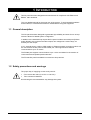
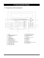
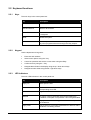
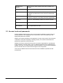
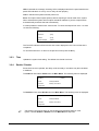
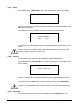
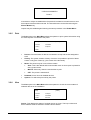
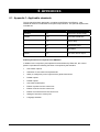
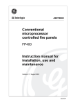
FP1500
Analogue Addressable Fire
Panel
User Guide
Version 2.1 / November 2003
Aritech is a GE Interlogix brand.
http://www.geindustrial.com/ge-interlogix/emea
© 2003 GE Interlogix B.V.. All rights reserved. GE Interlogix B.V. grants the right to reprint this manual for internal use
only. GE Interlogix B.V. reserves the right to change information without notice.
2
FP1500 User Guide
CONTENTS
1
Introduction............................................................................................................................................ 4
1.1 General description ....................................................................................................................... 4
1.2 Safety precautions and warnings.................................................................................................. 4
2
The Control Panel.................................................................................................................................. 5
2.1 General view of the control panel ................................................................................................. 5
2.2 Keyboard functions ....................................................................................................................... 6
2.2.1
Keys ............................................................................................................................... 6
2.2.2
Keypad........................................................................................................................... 6
2.2.3
LED indicators ............................................................................................................... 6
2.3 Access levels and passwords ....................................................................................................... 7
3
The User Menu....................................................................................................................................... 8
3.1 Introduction and menu access ...................................................................................................... 8
3.2 The main menu ............................................................................................................................. 8
3.2.1
Configure ....................................................................................................................... 8
3.2.2
Test ................................................................................................................................ 8
3.2.3
Time ............................................................................................................................... 9
3.2.4
Enable / Disable............................................................................................................. 9
3.2.5
Print.............................................................................................................................. 12
3.2.6
View ............................................................................................................................. 12
4
What to do in case of alarm or fault .................................................................................................. 14
5
Maintenance......................................................................................................................................... 15
5.1 By the user .................................................................................................................................. 15
5.2 By the maintenance company..................................................................................................... 15
6
Appendices .......................................................................................................................................... 16
6.1 Appendix 1: Applicable standards............................................................................................... 16
3
FP1500 User Guide
1 INTRODUCTION
This fire panel has been designed and manufactured in compliance with EN54-2 and
EN54-4 1997 standards.
This is a detailed manual for the proper use of the system. To avoid potential problems
and accidents, it is advised that manual is studied before using this equipment.
1.1 General description
This fire panel has been designed to guarantee high reliability and ease of use. Its loop
structure allows for flexible system configuration.
In addition to the standard loop outputs the fire panel includes: two serial ports (RS232
and/or RS485); two monitored sounder outputs; two voltage-free contact relays; an
auxiliary 24 VDC output.
A PC, external printer, modem, GSM modem or Ethernet network connection module can
be connected to the fire panel via the RS232 port. This supports short-distance
communications up to 15 metres.
The RS485 port supports communications up to 1.2 km and allows for the creation of
connected fire and repeater panels networks.
The FP1500 fire panel is available in one and two loop versions.
1.2 Safety precautions and warnings
The proper way of supplying current to the panel is:
•
First connect the mains (110 VAC or 230 VAC).
•
Then connect the batteries.
Not following this recommendation may damage the system.
4
FP1500 User Guide
2 THE CONTROL PANEL
2.1 General view of the control panel
1.
2.
3.
4.
5.
6.
7.
8.
9.
10.
11.
12.
13.
5
LCD
Navigation and enter ( ) keys
Alphanumeric keypad
Exit menu key
Change key
Language card slots
Earth Fault LED
Relays Disabled LED
Sounder Delay LED
Sounder Fault / Disabled LED
System Fault LED
Supply Fault LED
Out of Service LED
14.
15.
16.
17.
18.
19.
20.
21.
22.
23.
24.
25.
Silence Buzzer key / LED
Sounders Silence key / LED
Evacuation key / LED
Reset key
Sounders On key / LED
Test LED
Disabled LED
Fault LED
Fire LED
Supply On LED
Fault / Disabled / Test zone LED
Fire zone LED
FP1500 User Guide
2.2 Keyboard functions
2.2.1
Keys
The main keys in the control panel are:
2.2.2
Key
Description
Sounders On
Activates all sounders.
Sounders Silence
Silences all sounders.
Silence Buzzer
Silences the internal buzzer while an incident or fault is
investigated.
Reset
Resets the system.
Evacuation
Sets the system to alarm status releasing all sounders and
any other programmed events through the relay outputs.
Keypad
Use the alphanumeric keypad to:
2.2.3
•
Enter text and numbers.
•
Select menu options using the * key.
•
Cancel an operation and exit the current menu using the # key.
•
Confirm an entry using the key.
•
Navigate alarm faults in the display using the up / down arrow keys.
•
Navigate numeric fields using the left / right arrow keys.
LED indicators
The main LED indicators in the control panel are:
6
Key
Description
Supply On
Mains power is ON.
Fire
An alarm has been detected and is indicated in the
corresponding zone LED.
Fault
A general fault has been detected.
Disabled
An output or device has been disconnected making the
installation incomplete. Full protection cannot be guaranteed.
Test
Highlights that a test is being performed at a certain part of
the installation.
Supply Fault
The fire panel is not properly powered due to either a mains
shutdown or a battery problem.
FP1500 User Guide
Sounder Fault /
Disabled
One (or more) of the sounder outputs has a problem or is
disabled.
System fault
There is a malfunction in the fire panel.
Relays disabled
A relay output has been disabled. The fire panel is not able
to release any safety device in the event of a potential risk
situation.
Sounder Delay
The fire panel has detected a fire but has not activated the
sounders or relays as a time delay has been programmed.
Earth Fault
There is a current leakage. Cable runs must be checked.
Silence Buzzer
The internal buzzer has been silenced.
Out of Service
The fire panel does not work.
2.3 Access levels and passwords
Following EN54 standard (1997), part 2, the fire panel has different access levels as a
security measure. The configuration and control menus can be accessed only if the
appropriate password is entered.
Level 1: All the panel indications are operational, but only visual control of the fire panel
is allowed to verify that everything is working properly. The controls are blocked. No
password is required to access this level.
Level 2: This level is reserved for the person or persons responsible for controlling the
proper operation of the fire system. Up to 10 different passwords can be defined by the
installer. The user can access the panel controls and switch on and off zones and adjust
the time and the date, but cannot make changes in the configuration.
There are two additional access level reserved for the installation specialist and the
manufacturer.
7
FP1500 User Guide
3 THE USER MENU
3.1 Introduction and menu access
"
Instructions in this section refer to access level 2. See section 2.3 Access
levels and passwords.
The LCD has 4 lines of information of 40 characters each. The menu is structured in the
following way:
1
[MAIN MENU]
1. Configure
2
3
[# Exit]
4. Enable
2. Test
5. Disable
3. Time
6. Print
7. View
1. Menu title; 2. Menu options; 3. Use the # key to exit the current menu.
When set-up of the system is complete and all devices configured, the control panel
displays the following message:
***
***
ALL CONNECTED DEVICES
ARE AT NORMAL STATUS
00/00/0000
00:00
To access the user menu press and enter your password. Once the password has
been entered the Main Menu is displayed.
3.2 The main menu
[MAIN MENU]
3.2.1
[# Exit]
1. Configure
4. Enable
2. Test
5. Disable
3. Time
6. Print
7. View
Configure
The Configure option is not available to standard users. Configuration may only be
performed by qualified personnel.
3.2.2
Test
Allows tests on the panel LED indicators and display. From the Main Menu select Test.
The following options appear:
8
FP1500 User Guide
LED: If selected the message Checking LEDs is displayed and the fire panel switches the
panel LED indicators on one by one to verify all work properly.
LCD: If selected the system tests the panel LCD.
Zone: This option tests outputs (alarms) without requiring a manual reset of the system.
When selected the system asks if outputs should be released. If yes the outputs will be
activated briefly and then silenced automatically.
It is also possible to select which zones to test. To check the outputs from zone 1 to zone
10 enter the following:
Zone test
From Zone
: [001]
To Zone
: [010]
Release Outputs
: [YES]
The Test LED indicator will be lit and a test screen displayed in the LCD until the test is
completed.
To cancel all tests and / or return to the previous menu press the # key.
3.2.3
Time
Updates the system time setting. The default time format is 24 hour.
3.2.4
Enable / Disable
Zones, devices, the keyboard, the delay mode and relays / sounders may all be enabled
or disabled.
To Enable an item select Enable from the Main Menu. The following menu is displayed:
[ENABLE]
[# Exit]
1. Zone
4. Delayed Mode
2. Devices
5. Relay / Sounders
3. Keyboard
To Disable an item select Disable from the Main Menu. The following menu is displayed:
[DISABLE]
[# Exit]
1. Zone
4. Delayed Mode
2. Devices
5. Relay / Sounders
3. Keyboard
"
9
The following procedures apply to both enabling and disabling features of the
system. Choose Enable or Disable from the Main Menu as required.
FP1500 User Guide
3.2.4.1 Zone
Select Zone from the Disable Menu. The system will ask which zone is to be disabled .
Enter the zone to be modified.
Disable zone number : [001]
The fire panel will activate the internal buzzer to confirm a zone has been disabled. Press
to silence the buzzer.
A message will confirm the details of the event and the time it was performed.
Incidence : 1 of 1 at 00 :00
**ZONE DISABLED**
Panel: 1
Zone: 1
A disabled zone will be highlighted with the corresponding Disabled LED indicator on the
panel.
Devices assigned to a disabled zone will not be controlled by the fire panel but output
signals (sounders, relays) will remain active.
3.2.4.2
Devices
Every element of the installation can be enabled or disabled independently.
Select Devices from the Disable Menu. The system will ask for the loop number and the
device address.
Loop : [01] Address : [001]
Enter the loop number and the device address and press . The Disabled LED will be
activated.
The device may be enabled again following the same procedure in the Enable Menu.
Signals from a disabled device will not be processed by the fire panel but output signals
(sounders, relays) will remain active.
3.2.4.3
Keyboard
The control panel keyboard may also be disabled by selecting Keyboard from the
Disable Menu.
10
FP1500 User Guide
To re-activate the keyboard a level 2 access password must be entered (see section 2.3
Access levels and passwords).
3.2.4.4 Delayed mode
A time delay can be programmed in any zone for daylight hours or for a specified period
of the day. It may only be programmed in access level 3 (i.e. by the installer) but can be
disabled and enabled as required from access level 2.
Delay modes allow the user to verify the cause of the alarm before outputs (relays and
sounders) are activated.
When this option is enabled the corresponding LEDs of the front panel are switched on.
When the fire panel detects a fire and a delay has been programmed only the fire panel
internal buzzer is activated. Through the LCD display and corresponding LEDs, the
system informs the operator about the device that originated the alarm and that the
system is in the first phase of a delayed alarm.
By pressing the Silence Buzzer key, the system moves into the second delayed alarm
phase, normally programmed to be long enough to allow confirmation of the cause of the
alarm and apply the appropriate corrective actions.
If the Silence Buzzer key is NOT pressed, the system moves into the confirmed alarm
mode.
The fire panel must be Reset before the programmed delay for phase 2 has expired, else
the confirmed alarm will be triggered.
"
Manual call points always trigger a confirmed alarm situation as no delay is
allowed.
When Delayed Mode is selected, the system asks for the number of days that this delay
mode should be active. Using the * key enter the required number. Once activated, the
Delayed Mode LED is switched on.
"
To enable the delay mode permanently, enter 200 days.
3.2.4.5 Relay / Sounders
This option is useful to check the system without releasing the sounders and outputs.
Select Relay / Sounders from the Disable Menu and select the item to be disabled from
the following screen.
1. Sounders
[Enabled]
2. Relays
[Enabled]
An access level password is requested to complete this option and a confirmation screen
details the event.
11
FP1500 User Guide
Event: 1 of 1 at 00:00
**RELAYS DISABLED**
Panel: 1
If sounders or relays are disabled the fire panel will activate its internal buzzer to warn
that outputs have been disconnected. The internal buzzer can be silenced using the
Silence Buzzer key.
Outputs may be enabled again following the same procedure in the Enable Menu.
3.2.5
Print
The Print option in the Main Menu allows the operator to print system information using
an external printer connected to the panel.
[PRINT]
[# Exit]
1. Devices
4. Disabled
2. History
5. Options
3. Mode
3.2.6
•
Devices: Print the status of devices connected to a loop and the text assigned to
each.
•
History: The system records a history of events. It is possible to print all of these
events or only part of them (e.g. the events of the last week).
•
Mode: The printer may be in one of three modes:
•
Auto: This is the default and recommended mode. A short report is printed for
every system event.
•
Manual: Prints only when the user decides to print.
•
OFF: The printer is switched off.
•
Disabled: Print a list of all disabled devices.
•
Options: To select the port used by the printer.
View
The View option in the Main Menu allows the operator to check the current status of
selected devices in the installation.
[VIEW]
[# Exit]
1. Devices
4. Outputs
2. History
5. Disabled
3. Faults
6. Events
Device: This displays the status of a single device on a loop. The loop number and
device address must be entered to view the device details.
12
FP1500 User Guide
Loop: [01]
Zone: [01]
Address: [001]
Type:
Analogue value:
Zone:
Point:
History: Allows the operator to view the list of events that the system has recorded.
Navigate using the left / right keys on the keyboard.
Faults: View current faults in the system.
Outputs: View the status of sounders and relays. Use Enter or to jump from one
output to the next.
Details available:
•
If an output is enabled or disabled (ON/OFF).
•
If an alarm event (event 1) has occurred.
•
If an alarm event has occurred after a delay (event 2).
"
Relay
Status
Event 1
Event 2
1
ON
000
000
If the Sounders Silence key has been pressed before checking outputs all
sounders will be shown as OFF.
Disabled: Allows the operator to view zones and devices that have been disabled.
There are two options:
•
Zones: to check disabled zones either partially or completely.
•
Devices: to check disabled detectors across the installation.
Events: View all events recorded by the system. Each event is identified with a number
(from 1 to 999).
13
FP1500 User Guide
4 WHAT TO DO IN CASE OF ALARM OR FAULT
Read the following steps carefully. The operator must be familiar with the fire system and
control panel LED indicators to react effectively to an alarm situation.
1. KEEP CALM
In an alarm situation the fire panel activates the sounders. It is critical to remain calm at
this time so that the correct decisions may be taken and procedures followed.
2. PRESS ANY KEY AND ENTER THE USER PASSWORD
Any key enables the keyboard in an alarm situation. An access level password is
required.
3. SILENCE THE INTERNAL BUZZER
Use the Silence Buzzer key to silence the internal buzzer. Silencing sounders may also
help create better conditions to assess the situation in case of a possible fire (the
sounders are automatically reactivated after a few moments if the fire condition has not
been reset).
The cause of the alarm has still not been determined.
4. IDENTIFY THE CAUSE
The control panel LED indicators help identify the cause of the event that has triggered
the current alarm (e.g. fire, fault etc).
5. ACT
If an alarm situation is confirmed follow the emergency procedures defined for your site.
6. SYSTEM RESET
Reset the system when all incidents have been solved.
14
FP1500 User Guide
5 MAINTENANCE
Maintenance measures recommended in EN54-14 and any other applicable local
authority laws and requirements must be followed.
5.1 By the user
Daily: The control panel must indicate normal functioning. Any faults must be noted down
in the register and the maintenance company called. Check that any previously registered
faults have been fixed.
Monthly: As a minimum, a manual call point or detector must be activated to test the
control panel and the alarm devices connected to it. It is recommended to test a different
zone every month. Any malfunction should be written down in the register, taking
corrective measures as soon as possible.
Batteries: The batteries must be replaced periodically as recommended by the
manufacturer. The useful life of the battery is 4 years. Avoid the total discharge of the
batteries.
Cleaning: The exterior of the control panel should be cleaned with a damp cloth. Do not
use solvents or liquids.
5.2 By the maintenance company
Quarterly:
•
Check the entries in the on-site register and the records of the control panel,
implementing the appropriate corrective actions as required.
•
Check all the battery connections and the voltage.
•
In each zone, check the fire alarms, faults and auxiliary functions of the control and
signalling equipment.
•
Check the control and signalling equipment to determine a possible increase in
humidity or any other type of deterioration.
•
Check if there has been any structural alteration that may affect the functioning of
the detectors, manual call points or sounders.
•
Any defect must be noted down in the on site register and the corrective actions
taken as soon as possible.
Annually:
15
•
Put the control panel in “Test” and check the configuration of the system. Verify that
all the detectors and manual call points work according to the manufacturer’s
recommendations and programmed configuration.
•
Visually inspect all the equipment connections and make sure they are safely
fastened, that they have not been damaged and that they are appropriately
protected.
•
Examine and test all batteries.
•
Any defect must be noted down in the on site register and corrective action taken as
soon as possible.
FP1500 User Guide
6 APPENDICES
6.1 Appendix 1: Applicable standards
This fire panel has been designed in compliance with EN54-2 and EN54-4: 1997
standards. EN54-2 includes basic and optional requirements. The optional requirements
included are:
Subject
Section
Name
Indication
8.4
Total loss of power supply
Controls
7.12
Coincidence detection
7.11
Output delay
9.5
Disconnection of an
addressable point
10
Test status
7.8
Fire alarm device output
Outputs
Auxiliary functions not required in the EN54-2/4
In addition to the compulsory and optional functions defined by EN54-2/4, this control
panel incorporates the following functions not required by the standard.
16
•
Auto-search options.
•
Allocation of 10 access level 2 passwords.
•
Ability to configure by zone: logical events, general events etc.
•
RS485 outputs.
•
RS232 outputs.
•
Auto-search serial ports.
•
Edition of points from the control unit.
•
Edition of zones from the control unit.
•
Edition of manoeuvre from the control unit.
•
Storage of events in a history file.
•
Language selection.
FP1500 User Guide
ISO9001 Certified
1046244