1
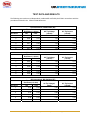
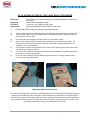
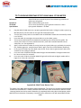
 TECHNICAL NOTE
OK INTERNATIONAL & METCAL SOLDERING SYSTEMS
ELECTRICAL OVERSTRESS, ELECTROSTATIC DISCHARGE
STATEMENT OF COMPLIANCE
All OK International (Oki) and Metcal soldering, desoldering and rework systems are designed and
tested to meet or exceed all applicable ESD and EOS Standards listed below as they apply to
soldering products.
OK International (Oki &Metcal branded) soldering systems offer superior EOS/ESD protection. Because
our soldering systems deliver continuous current, they cannot generate switching transients.
Typical values for tip-to-ground resistance and tip potential are 0.8 ohms and 1.0mV RMS, well within the
MIL-STD and Commercial / International specifications.
OK International also offers extra protection against potential ground faults in its MX and MFR Series
Soldering Systems with an Auto - Off feature. This feature senses the DC continuity (resistance) of the
output cable and handle assembly through the cartridge. If the resistance of the output circuit exceeds a
preset reference level, the system is turned off. This is fail-safe protection against any ground loss.
On the OK International MFR Series and the Metcal MX-5000 Series soldering systems, a ground fault
monitor is built into the power supply to continuously monitor the AC supply (mains) ground circuit. In the
event of a mains ground failure or if the mains ground should go out of specification; the system is
immediately switched off and the system cannot be re-powered until the mains ground is restored.
OK International also protects against ESD by using static dissipative materials (
] ohms/sq
surface resistivity) for all surfaces that are in direct contact with soldered components. And where
possible, Metcal uses static dissipative materials with the stricter surface resistivity of
ohms/sq. This limits the opportunity for any substantial static charge build-up.
However, the user concerned with ESD protection must still insure that the work surface is made of static
dissipative material and is properly grounded. A static dissipative surface insures efficient, but controlled,
dissipation of static charges. Dissipative surfaces will also distribute the charge over the entire surface
area, limiting the possibility of point charge buildup. For information on how to check static dissipative
material for surface resistivity, see Testing Methods.
APPLICABLE STANDARDS
Tip‐to‐ground resistance Ac Tip Voltage Tip leakage current Tip Transient voltage STM13.1‐2000 J STD‐001D < 2 ohm < 20mV RMS < 10 mA AC no reference made in document < 5 ohm N/A N/A < 2V peak MIL‐STD < 5 ohm < 2mV RMS N/A no reference made in document J STD‐001D only mentions that the AC and DC leakage currents from tip to ground should not create deleterious effects on the equipment/components, but does not explicitly state limits . 12151 Monarch Street, Garden Grove, CA 92841 • +1 714 799-9910 • +1 714 799-9533 fax • www.okinternational.com
TEST DATA AND RESULTS
The following test results were independently conducted & verified by the ESDA in accordance with the procedures outlined in the STM13.1‐2000 document. OK International, PS900/PS800 (RF)
Tip to Ground
Resistance (< 2ohm)
AC Tip Voltage
Data Point
Hot
Cold
(<20mV)
AC Tip Current
(<10mA)
1
0.44
0.50
1.70
0.32
2
0.38
0.50
1.70
0.32
3
0.40
0.40
1.70
0.33
4
0.41
0.40
1.70
0.32
5
0.41
0.40
1.70
0.32
6
0.41
0.40
1.70
0.32
OK International, MFR PS1K/PS2K/1100/2200 (RF)
Tip to Ground
Resistance (< 2ohm)
AC Tip Voltage
Data Point
Hot
(<20mV)
Cold
AC Tip Current
(<10mA)
1
0.40
0.40
1.70
0.17
2
0.38
0.40
1.70
0.17
3
0.38
0.40
1.70
0.17
4
0.39
0.40
1.70
0.17
5
0.38
0.40
1.70
0.17
6
0.38
0.40
1.70
0.17
OK International, MX-500/5000 (RF)
Tip to Ground
Resistance(< 2 ohm)
AC Tip Voltage(<
Data Point
Hot
20mV)
Cold
AC Tip Current
(<10mA)
1
0.55
0.30
0.40
0.23
2
0.50
0.30
0.40
0.23
3
0.50
0.30
0.40
0.23
4
0.49
0.30
0.30
0.23
5
0.49
0.30
0.40
0.23
6
0.49
0.30
0.30
0.23
12151 Monarch Street, Garden Grove, CA 92841 • +1 714 799-9910 • +1 714 799-9533 fax • www.okinternational.com
TIP-TO-GROUND POTENTIAL TEST USING WAHL ST2200 METER
References:
Equipment:
Threshold:
Specification:
1)
Wahl ST2200 user manual Purpose of test: Measuring potential of solder tip to
AC ground.
Wahl ST2200 soldering iron tester
pre-set at ≤ +2mV RMS (AC ONLY test)
tip-to-ground potential ≤ +2mV RMS (AC ONLY test)
Plug the Wahl ST2200 meter into a properly grounded wall outlet.
2)
Plug the solder system (e.g. MX-500) directly into the outlet on the right side of the Wahl meter.
3) Turn the select rotary switch on the Wahl meter to MILLIVOLTS AC ONLY. Make sure the flip switch selector is on TIP TEST. Insert the solder tip cartridge to be tested and turn on the solder system. The tip to be tested should be cleaned before conducting test (ref OKI Tip Care guide). The sensor of the solder iron tester should also be fairly clean and not blackened with burned solder/flux, etc. (See appendix A). Firmly touch the solder tip to the Wahl meter sensor. Ensure there is good contact. Wait a few seconds for the reading to stabilize. For a test result of PASS the FAIL/MV OHM LED light should be GREEN. The digital readout will be ≤+2mV for tip‐to‐ground potential. For a test result of FAIL the FAIL/MV OHM LED light will be RED. The digital readout will be >+2mV for tip‐to‐ground potential. 4) 5) 6) 7) 8) Appendix A: Wahl Tester Sensor Care The sensor of the Wahl meter should be cleaned periodically. The sensor can get built up with blackened residue from the solder/flux from taking other measurements like tip temperature. A medium stiffness brush and warm water can be used to clean the sensor. Isopropyl alcohol can also be used if allowed to dry completely before using the unit and proper caution observed. Re‐tin the sensor if necessary. Use solder wick to clean then re‐tin with a small bead of fresh solder. 12151 Monarch Street, Garden Grove, CA 92841 • +1 714 799-9910 • +1 714 799-9533 fax • www.okinternational.com
TIP-TO-GROUND RESISTANCE TEST USING WAHL ST2200 METER
References: Equipment: Threshold: Specification:
1) Wahl ST2200 user manual Purpose of test: Measuring resistance of solder tip to AC ground. Wahl ST2200 soldering iron tester set at 5 ohms Specification: tip‐to‐ground resistance ≤ 5 ohms tip-to-ground resistance < 5 ohm
Plug the Wahl ST2200 meter into a properly grounded wall outlet. 2) Plug the solder system (e.g. MX‐500) directly into the outlet on the right side of the Wahl meter. Turn the select rotary switch on the Wahl meter to RESISTANCE. Make sure the select flip switch is on TIP TEST. Insert the solder tip cartridge to be tested and turn on the solder system. The tip to be tested should be cleaned before conducting test (ref OKI Tip Care guide). The sensor of the solder iron tester should also be fairly clean and not blackened with burned solder/flux, etc. (See appendix A). Apply a small amount of solder on the tip (can be any typical solder type, preferably low activity flux, medium gage wire, example Kester Sn96.5, Ag3.0, Cu0.5 flux 275/0.031diam (lead‐free)). Firmly touch the solder tip to the Wahl meter sensor. Ensure there is good contact. Wait a few seconds for the reading to stabilize. For a test result of PASS the FAIL/MV OHM LED light should be GREEN. The digital readout will be 5 ohms or below for resistance. For a test result of FAIL the FAIL/MV OHM LED light will be RED and the digital readout will be higher than 5 ohms for resistance. 2) 3) 4) 5) 6) 7) 8) Appendix A: Wahl Tester Sensor Care
The sensor of the Wahl meter should be cleaned periodically. The sensor can get built up with blackened
residue from the solder/flux. A medium stiffness brush and warm water can be used to clean the sensor.
Isopropyl alcohol can also be used if allowed to dry completely before using the unit and proper caution
observed. Re-tin the sensor if necessary. Use solder wick to clean then re-tin with a small bead of fresh
solder.
12151 Monarch Street, Garden Grove, CA 92841 • +1 714 799-9910 • +1 714 799-9533 fax • www.okinternational.com