1
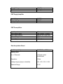
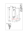
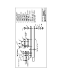
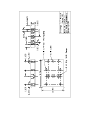
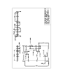
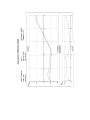
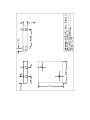
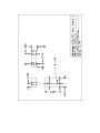
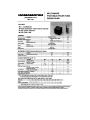
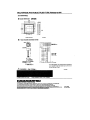
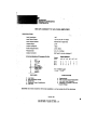
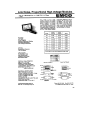
Bibliography
Carroll, Bradley W., & Ostlie, Dale A. (1996) Modern Stellar Astrophysics.
New York: Addison-Wesley Publishing Company, Inc.
Franco, Sergio (1995). Electric Circuits Fundamentals. New York:
Saunders College Publishing.
Guidelines for the Preparation and Submission of Theses and Written
Creative Works. (1993). San Francisco State University Graduate
Division Office. San Francisco, Ca.
Hardy, John W. (1998). Adaptive Optics for Astronomical Telescopes.
New York: Oxford University Press.
Houp, Kenneth W., Pearsall, Thomas E., & Tebeaux, Elizabeth. (1998).
Reporting Technical Information (9th ed.). Needham Heights, Ma: Allyn &
Bacon.
Melles Griot 1997-98: Optics, Fiber Optics, Tables & Hardware, Lasers,
Instruments & Lab Accessories. (1997). Irvine, Ca: Melles Griot.
Mohan, Ned, Undeland, Tore M., & Robbins, William P. (1989). Power
Electronics (2nd ed.). New York: John Wiley & Sons, Inc.
Montgomery, Douglas C., & Runger, George C. (1999). Applied Statistics
and Probability for Engineers (2nd ed.). New York: John Wiley & Sons,
Inc.
Nanomotion II. 11 NCS 101/IEEE User Manual. (1998). Irvine, Ca:
Melles Griot.
New Focus, Inc. 1997/98 Catalog, Vol. 8. (1997). Santa Clara, Ca: New
Focus, Inc.
Nise, Norman S. (1995). Control Systems Engineering (2nd ed.).
Redwood City, Ca: The Benjamin/Cummings Publishing Company, Inc.
PCI-20093W-1 Analog Output Board and PCI-20369S Master Link
Software Libraries Manual. (1993). Arizona: Intelligent Instrumentation,
Inc.
PCI-20428W-1A, -2A, -3A Multifunction Boards and Master Link Software
Libraries Manual. (1997). Arizona: Intelligent Instrumentation, Inc.
Physik Insrumente: Nano Positioning, 1998 Waldbronn, Germany: Physik
Instrumente.
Rohlf, James W. (1994). Modern Physics from α to Z0. New York : John
Wiley & Sons, Inc.
Sen, P.C. (1997). Principles of Electric Machines and Power Electronics
(2nd ed.). New York : John Wiley & Sons, Inc.
Tipler, Paul A. (1995). Physics For Scientists and Engineers (3rd ed.).
New York: Worth Publishers.
Visual Designer 4.0 User Manual. (1998). Arizona: Intelligent
Instrumentation, Inc.
Wangness, Roald K. (1986). Electromagnetic Fields (2nd ed.). New York:
John Wiley & Sons, Inc.
APPENDICES
A1: Specifications
Optical Table
Average Mirror Reflectance
Average Total Light Transmission
Tip/Tilt Range/Axis
Tip/Tilt Resolution/Axis
Maximum Angular Velocity of Tip/Tilt Mirror
Maximum bandwidth for arcsecond
corrections
>98% for λ>400nm
>96% for λ>400nm
3 degrees
0.25 nanoradians
62.5 mrad/s
70Hz
Beamsplitter
First Surface Reflectance
Second Surface Reflectance
Total Light Transmission
Incedence Angle
Angular Range of Mount
Angular Resolution of Mount
Avg 4% in Visible
Wavelengths
Avg 0.5% in Visible
Wavelengths
~94%
45 degrees
10 degrees/axis
6 arcseconds/axis
PMT
Peak Quantum Effeciency
Peak Spectral Response
20% (400nm)
60mA/W (350-450nm)
Supply Voltage
Dark Current
Gain
800VDC
0.065nA/anode
1.8 x 10⁷
PMT Supply Amplifier
Input Voltage
Output Voltage
Voltage Ripple
9.9VDC
800VDC
0.025%
PMT Preamplifiers
Input Impedance
Input Signal Range
Input Range Selector
Output Range
Output Impedance
Power Requirements
1kΩ
1pA-1uA per 1V output
Remote via 3 logic lines
±10V
100Ω
±15V, 50mA
Data Acquisition Board
Bus Compatability
Analog Input
PC/XT/AT and EISA
No. of Channels
16 Single ended
8 differential
Resolution
12 bits
Voltage ranges (jumper selectable)
±5V, ±10V, 0-5V, 0-10V
Selected Range
0-10V
Gain Ranges (jumper Selectable)
1, 10, 100
Selected Gain
1
Offset Voltage
±2.44mV max
Bias Current
500pA
Input Impedance
109Ω/10pF
Noise (Gain=1)
Analog Output
0.5 LSB RMS max
No. of Channels
2
Resolution
12 bits
Voltage Ranges (jumper selectable)
±5V, ±10V, 0-10V
Selected Voltage Range
0-10V
Offset Voltage
±2.44mV max
Output Current
Digital I/O
±5mA
No. of 8 bit Ports
2 (1 input, 1 output)
Digital I/O levels
System Throughput
TTL Compatible
Multi-Channel Analog Input or Analog Output
Under DMA Control
DMA Channels
0-100kHz
Number supported
2 (1 Input, 1 Output)
PC Channels Supported (jumper selectable)
DMA 1, DMA 3
Input Mode
Start on trigger or start on
command, using a linear
or circular buffer
Output Mode
Start on command, using
a linear or circular buffer
PC
Processor
RAM
Hard Drive Capacity
Operating System
Control Software
Pentium 166MHz
32Mbytes
1.6Gbytes
Windows 95
Visual Designer 4.0 by
Intelligent Instrumentation
Overall System Specifications
Total Light Transmission
Bandwidth
Field of View (largest correction due to
position sensor active area limitations)
Range of Motion at Slit
Resolution
Maximum Slew Rate
Stellar Range
88.5% in the visible spectrum
25Hz
±11 Arcseconds
±72.1mm
1.3 milliarcseconds
326.8 Arcseconds/second
V=0-9 stellar magnitudes
A2: Operating Instructions
Setup for an Observing Run
1. Boot up PC and open the Visual Designer software by clicking Start à
Programs à Visual Designer à Visual Designer - Run.
2. Power up tip/tilt driver (black box next to PC).
3. Run program TIPTILTALIGN.DGM in the C:tiptilt directory. Follow the
runtime instructions of this program as summarized in 4-26.
4. Install laser into polar axis mount.
5. Adjust laser until beam passes through the slit and is aligned with the
center of the collimator.
6. Install link between optical table and polar quartz lamp.
7. Install beamsplitter.
8. Adjust pick-off mirror #1 until laser hits the center of the tip/tilt mirror.
9. Adjust pick-off mirror #2 until laser passes through the slit and hits the
center of the collimator. If this cannot be achieved, it may be
necessary to re-adjust the home position of the tip/tilt mirror and the
position of pick-off mirror #2 simultaneously. The home position of the
tip/tilt mirror can be adjusted by entering new values in the x-home and
y-home fields of the run time screen. The final values must be
recorded and changed in the TIPTILTRUN.DGM program. Do not
change these values unless absolutely necessary.
10. Very Important!! Insert Neutral density filter on face of laser to avoid
overexposing the PMT.
11. Plug in BNC and DB-15 cables between PC and PMT signal converter
located in the rack next to the slit room doorway.
12. Turn on power switch located in the bottom, left hand corner of the
Signal converter.
13. Turn off lights in slit room.
14. Open both diaphragms in PMT baffle tube.
15. Close control loop by clicking the switch on the display screen and
shut off monitor.
16. Adjust beamsplitter until laser is centered on the slit.
17. Turn on monitor and open control loop by clicking switch on display
back to open loop position.
18. Close diaphragms in PMT baffle tube.
19. Laser should still be centered on the slit.
20. Remove optical table - polar quartz link.
21. Remove laser from polar axis.
22. Re-install optical table - polar quartz link.
23. Stop TIPTILTALIGN.DGM program.
24. Run TIPTILTRUN.DGM.
25. Turn off monitor.
26. Follow Nightly Setup instructions.
Nightly Setup
1. Open diaphragms in PMT Baffle Tube.
2. Close loop on first star.
3. If star does not go to the slit, adjust beamsplitter mount until the
desired position is reached.
4. System is now aligned.
Run Time Operations
1. When Star is within a couple arcseconds of slit, enable tip/tilt by
moving "tip/tilt" switch to "enabled".
2. When observation is complete, disable "tip/tilt" switch.
-
Should star be lost or tip/tilt seems to fail, disable "tip/tilt switch,
complete observation and check status display on the monitor in the
slit room for further instructions.
It may be necessary to slightly re-adjust the beamsplitter position if the
star is not centered perfectly on the slit during tip/tilt operation.
3. At end of night, just make sure tip/tilt switch is in the "disabled" position
and close PMT baffle tube diaphragms.
System Shutdown and Removal Procedures at end of Run
1. Shut down Visual Designer program.
2. Shut down PC.
3. Remove beamsplitter and store properly.
4.
5.
6.
7.
Close diaphragms in PMT baffle tube.
Power off tip/tilt driver.
Power off signal converter.
Remove optical table - polar quartz link and slide optical table out of
light path.
8. Cover optical table mirrors.
9. Unplug PC to signal converter cables and store under PC desk.
A3: Parts List
Part
Vendor
P/N
Total
Cost ($)
UCO/Lick Optical
Shop
N/A
N/A
02MPQ011/03
8
198.00
Optical Table
Pick-Off Mirrors
Tip/Tilt Mirror
Melles Griot
650.00
Mirror Coatings
Denton Vacuum
FSS-99
N/A
Base Plates
Pick-Off Mirror
Mounts (2)
UCO/Lick Machine
Shop
N/A
256.00
J36-482
N/A
Edmund Scientific
N/A
Mirror Clips
Tip/Tilt Actuator
3,295.00
UCO/Lick Machine
Shop
07MCD015
Melles Griot
N/A
N/A
Tip/Tilt Actuator
Mounting Plates
Optical Table Link
UCO/Lick Machine
Shop
N/A
N/A
N/A
N/A
Rubber Stopper
Misc. Hardware
UCO/Lick Machine
Shop
N/A
N/A
UCO/Lick Machine
Shop
N/A
Beamsplitter and
PMT Assy.
Beamsplitter
OptoSigma
03-2480
170.00
Beamsplitter Mount
Melles Griot
07MHT037
91.00
Mounting Plates
N/A
N/A
J36-623
42.25
J52-304
115.50
J03-630
19.00
J03-632
115.50
J54-630
42.00
J53-483
33.75
J52-298
19.00
J52-295
42.00
J52-292
63.00
N/A
N/A
R5900-01-M4
1,345.00
E7083
335.00
N/A
N/A
EMCO High Voltage
L10W
77.00
Advanced Research
PMT-5R
3,240.00
UCO/Lick Machine
Shop
PMT Baffle Tube
Iris Diaphragm
Edmund Scientific
48mm Ring Mount
(2)
Double Female
Thread
Ring
Edmund Scientific
Edmund Scientific
Edmund Scientific
Iris Diaphragm
Barrel
15mm Extension (2)
C-to-T Thread
Adapter
Edmund Scientific
Edmund Scientific
Edmund Scientific
Double Male Thread Edmund Scientific
Ring
Edmund Scientific
25mm Extension (2)
N/A
25mm Holder (2)
Hamamatsu
PMT Housing
Hamamatsu
PMT
UCO/Lick
Observatory
PMT Socket
Misc. Hardware
PMT Signal
Converter
PMT Supply Amp
PMT Preamplifiers
(4)
Instruments
Corporation
123490
39.95
N/A
N/A
Jameco Electronics
Preamplifier power
supply
N/A
Misc. Hardware
Controller
PC
Hi-Tech USA
N/A
560.47
Visual Designer 4.0
Intelligent
Instrumentation
PCI-20909S-1
695.00
PCI-20428W1
445.00
Multifunction I/O
Board
Intelligent
Instrumentation
PCI/GPIB Interface
W/ Software & Cable
60.00
PCI-20428K-1
Termination Panel
Intelligent
Instrumentation
570.00
777158-51
N/A
National Instruments
N/A
PMT Power Supply
Tip/Tilt Driver
Misc. Hardware
UCO/Lick Electronics
Shop
4,400.00
11NCS101/IE
EE
Melles Griot
N/A
N/A
N/A
A4: Component Datasheets and Mechanical Drawings
Optical Table Mechanical Drawings
-
Optical Table Mounting Surface
Assembled Optical Table
Optical Table Assembly Drawing
Mirror Layout
Pick-off Mirror Mounts
Tip/Tilt Mirror Mounting Plate #1
Tip/Tilt Mirror Mounting Plate #2
Baseplate #1
Baseplate #2
Baseplate #3
Optical Table Datasheets
-
Nanomover Actuators
Nanomover 1 Calibration Graph
Nanomover 2 Calibration Graph
Nanomover Gimbal Mount Kit
Sample FSS-99 Ag Coating Curve
Beamsplitter and PMT Mount Assembly Drawings
-
Assembled PMT-B/S Mount
Beamsplitter and PMT Mount Assembly
B/S-PMT Mounting Plate #1
B/S-PMT Mounting Plate #2
B/S-PMT Mounting Plate #3
B/S-PMT Mounting Plate #4
B/S-PMT Mounting Plate #5
B/S-PMT Mounting Plate #6
PMT Housing
PMT Baffle Tube
Beamsplitter and PMT Mount Assembly Datasheets
-
Kinematic Beamsplitter Mount
Beamsplitter
PMT & Socket
PMT Signal Converter Drawings
-
Signal Converter Diagram
PMT Signal Converter Datasheets
-
PMT Preamplifiers
PMT Supply Amplifier
Controller Drawings
-
Controller I/O Wiring Diagram
PMT Power Supply Schematic
Controller Datasheets
-
PC
Multifunction I/O Board
PCI/GPIB Interface
Nanomover System II Tip/Tilt Driver
Nano Micropositioning Systems
A5: Experimental Data