1
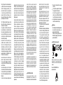
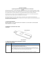
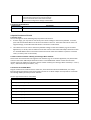
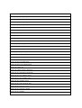
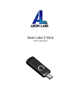
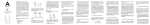
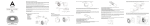
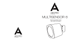
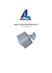
Aeotec by Aeon Labs Z-Stick .
Aeon Labs Z-Stick Gen5 is a selfpowered Z-Wave® USB adapter with
network creation capabilities
(independent from external power and
host microprocessor). By being able
to remotely include/remove Z-Wave
devices, this greatly simplifies Z-Wave
network installation. When connected
to a host controller (via USB), it enables
the host controller to take part in the
Z-Wave Network.
The Z-Stick Gen5 is also device
firmware upgradeable by the end
consumer. This enables the product
to always have the latest Z-Wave
protocol, capabilities and commands.
View the expanded manual:
http://aeotec.com/support
By taking advantage of the Z-Wave
mesh network, commands can
be routed to their destination via
intermediary “listening” Z-Wave
products. Products that are Z-Wave
certified can be used and communicate
with other Z-Wave certified devices.
Familiarize yourself with
your Z-Stick .
Quick start.
The Z-Stick
Gen5 operates in
SerialAPI-Mode. Both Inclusion-Mode
and Removal-Mode require that the
Z-Stick to be plugged into the USB
connector of the host. Software drivers
for the “ZW050x_USB_VCP_PC_
Driver” may need to be installed for
the Z-Stick to be recognized on some
computers(drivers can be found at
http://www.aeotec.com/support).
SerialAPI-Mode: Allowing a Host
Processor To Take Control of the
Z-Stick and Take Part in the Z-Wave
Network
To initiate SerialAPI-Mode, plug the
Z-Stick into the USB connector of the
host.
Note:
1). While in SerialAPI-mode, the
Z-Stick is always listening (it is awake
and always in RX receive mode) for
instructions and acts as a Z-Wave
adapter and responds to commands
sent through USB by the host processor
software.
2). Pressing the Action Button will not
have any effect while in SerialAPIMode. But short pressing the Reset
Button will reset the USB port.
Action Button
Reset Button
Installation and Maintenance
Application (IMA) feature.
The IMA feature only can be used
in Serial API-Mode for Z-Stick Gen5,
it can measure the network health
for each device in the network. The
different colour of LED indicates the
communication quality between the
Z-Stick Controller and devices in the
network.
Install the IMA tool software first (note:
the IMA tool can be downloaded from
here: http://www.aeotec.com/support).
Select the node device and then click
the IMA test button to start the IMA test
between the Central Controller and the
node devices. Your IMA tool client will
receive the test result via the different
colour of LED icon to indicate the
network health level and its colour will
be changed follow with the change of
network health level. If the color of LED
is changed to green
, which means
the current network quality is good. If
the color of LED is changed to orange
, which means the current network
quality is acceptable but latency can
occur. If the color of LED is changed
to red
, which means the current
network quality is insufficient. If the IMA
tool return a , which means the current
network is critical because a node is
not responding.
Upgrading the Z-Stick with
the Latest Software.
1. Download the Aeon Labs Z-Stick
Gen5 firmware upgrade software
that contains the firmware update
and UART to USB driver at http://
www.aeotec.com/support and run the
downloaded program.
2. Follow the on screen instructions to
complete installation.
Technical specifications.
Power Supply: USB DC 4.75V to 5.25V.
Max Operating Current: 100mA.
Operating Temperature: 0 C to 50 C .
Storage Temperature: -20 C to 70 C .
Operating Distance: Up to1310 feet/400
metres outdoors.
Warranty.
Aeon Labs warrants to the original
purchaser of Products that for the
Warranty Period (as defined below),
the Products will be free from material
defects in materials and workmanship.
The foregoing warranty is subject
to the proper installation, operation
and maintenance of the Products in
accordance with installation instructions
and the operating manual supplied to
Customer. Warranty claims must be
made by Customer in writing within
thirty (30) days of the manifestation of
a problem. Aeon Labs' sole obligation
under the foregoing warranty is, at
Aeon Labs' option, to repair, replace
or correct any such defect that was
present at the time of delivery, or to
remove the Products and to refund the
purchase price to Customer.
The "Warranty Period" begins on the
date the Products is delivered and
continues for 12 months.
Any repairs under this warranty must
be conducted by an authorized Aeon
Labs service representative and under
Aeon Labs' RMA policy. Any repairs
conducted by unauthorized persons
shall void this warranty.
Excluded from the warranty are
problems due to accidents, acts of
God, civil or military authority, civil
disturbance, war, strikes, fires, other
catastrophes, misuse, misapplication,
storage damage, negligence, electrical
power problems, or modification to the
Products or its components.
Aeon Labs does not authorize any
person or party to assume or create
for it any other obligation or liability in
connection with the Products except as
set forth herein.
Aeon Labs will pass on to Customer
all manufacturers’ Material warranties
to the extent that they are transferable,
but will not independently warrant any
Material.
Customer must prepay shipping and
transportation charges for returned
Products, and insure the shipment or
accept the risk of loss or damage during
such shipment and transportation.
Aeon Labs will ship the repaired or
replacement products to Customer
freight prepaid.
Customer shall indemnify, defend,
and hold Aeon Labs and Aeon Labs'
affiliates, shareholders, directors,
officers, employees, contractors,
agents and other representatives
harmless from all demands, claims,
actions, causes of action, proceedings,
suits, assessments, losses, damages,
liabilities, settlements, judgments, fines,
penalties, interest, costs and expenses
(including fees and disbursements
of counsel) of every kind (i) based
upon personal injury or death or injury
to property to the extent any of the
foregoing is proximately caused either
by a defective product (including strict
liability in tort) or by the negligent or
willful acts or omissions of Customer or
its officers, employees, subcontractors
or agents, and/or (ii) arising from
or relating to any actual or alleged
infringement or misappropriation of
any patent, trademark, mask work,
copyright, trade secret or any actual or
alleged violation of any other intellectual
property rights arising from or in
connection with the products, except to
the extent that such infringement exists
as a result of Aeon Labs' manufacturing
processes.
IN NO EVENT SHALL AEON LABS BE
LIABLE FOR ANY INDIRECT, INCIDENTAL,
PUNITIVE, SPECIAL OR CONSEQUENTIAL
DAMAGES, OR DAMAGES FOR LOSS OF
PROFITS, REVENUE, OR USE INCURRED
BY CUSTOMER OR ANY THIRD PARTY,
WHETHER IN AN ACTION IN CONTRACT,
OR TORT, OR OTHERWISE EVEN IF ADVISED
OF THE POSSIBILITY OF SUCH DAMAGES.
AEON LABS' LIABILITY AND CUSTOMER'S
EXCLUSIVE REMEDY FOR ANY CAUSE OF
ACTION ARISING IN CONNECTION WITH
THIS AGREEMENT OR THE SALE OR USE
OF THE PRODUCTS, WHETHER BASED
ON NEGLIGENCE, STRICT LIABILITY,
BREACH OF WARRANTY, BREACH OF
AGREEMENT, OR EQUITABLE PRINCIPLES,
IS EXPRESSLY LIMITED TO, AT AEON
LABS' OPTION, REPLACEMENT OF, OR
REPAYMENT OF THE PURCHASE PRICE
FOR THAT PORTION OF PRODUCTS
WITH RESPECT TO WHICH DAMAGES
ARE CLAIMED. ALL CLAIMS OF ANY KIND
ARISING IN CONNECTION WITH THIS
AGREEMENT OR THE SALE OR USE OF
PRODUCTS SHALL BE DEEMED WAIVED
UNLESS MADE IN WRITING WITHIN THIRTY
(30) DAYS FROM AEON LABS'S DELIVERY,
OR THE DATE FIXED FOR DELIVERY IN
THE EVENT OF NONDELIVERY.
THE INDEMNITY AND WARRANTY IN
ABOVE ARE EXCLUSIVE AND IN LIEU
OF ALL OTHER INDEMNITIES OR
WARRANTIES, WHETHER EXPRESS
OR IMPLIED, INCLUDING THE IMPLIED
WARRANTIES OF MERCHANTABILITY AND
FITNESS FOR A PARTICULAR PURPOSE.
FCC NOTICE (for USA)
THE MANUFACTURER IS NOT
RESPONSIBLE FOR ANY RADIO OR TV
INTERFERENCE CAUSED BY UNAUTHORIZED
MODIFICATIONS TO THIS EQUIPMENT.
SUCH MODIFICATIONS COULD VOID THE
USER’S AUTHORITY TO OPERATE THE
EQUIPMENT.
STORE INDOORS WHEN NOT IN USE.
SUITABLE FOR DRY LOCATIONS. DO
NOT IMMERSE IN WATER. NOT FOR USE
WHERE DIRECTLY EXPOSED TO WATER.
This device complies with Part 15 of
the FCC Rules. Operation is subject to
the following two conditions:
1 This device may not cause harmful
interference, and
2 This device must accept any interference
received, including interference that
may cause undesired operation.
This equipment has been tested
and found to comply with the
limits for a Class B digital device,
pursuant to part 15 of the FCC
Rules. These limits are designed
to provide reasonable protection
a g a i n s t h a r m f u l interference
in a residential installation. This
equipment generates, uses and
can radiate radio frequency energy
and, if not installed and used in
accordance with the instructions, may
cause harmful interference to radio
communications. However, there is
no guarantee that interference will
not occur in a particular installation.
If this equipment does cause harmful
interference to radio or television
reception, which can be determined
by turning the equipment off and
on, the user is encouraged to try to
correct the interference by one or
more of the following measures:
Reorient or relocate the receiving
antenna.
Increase the separation between
the equipment and receiver.
Connect the equipment into an
outlet on a circuit different from that
to which the receiver is connected.
Consul the dealer or an experienced
radio/TV technician for help. Warning
Do not dispose of electrical appliances
as unsorted municipal waste, use
separate collection facilities.
Contact your local government for
information regarding the collection
systems available.
Certifications (regional):
Z-Wave and Z-Wave Plus are registered
trademarks of Sigma Designs and its
subsidiaries in the United States and other
countries
Version:501009000001-AA
www.aeotec.com
Aeon Labs Z-Stick Gen5
Engineering Specifications and Advanced Functions for Developers
(V1.00)
Aeon Labs Z-Stick Gen5 is a Z-Wave USB adapter. When it connects to a host controller (via USB), it enables
the host controller to take part in the Z-Wave Network. You can use the PC Controller application to control
your Z-Wave devices via its Serial API function, this greatly simplifies Z-Wave network installation.
The Z-Stick Gen5 is also device firmware upgradeable by the end consumer. This enables the product to
always have the latest Z-Wave protocol, capabilities and commands.
By taking advantage of the Z-Wave mesh network, commands can be routed to their destination via
intermediary “listening” Z-Wave products. Products that are Z-Wave certified can be used and communicate
with other Z-Wave certified devices.
1. Technical Specifications
Operating distance: Up to 500 feet/150 metres outdoors in normal mode or 1310 feet/400
metres outdoors in PA mode.
2. Familiarize Yourself with Your Z-Stick
2.1 Interface
3. Independence Mode and Serial API-Mode Functions
3.1 Function of Action Button
Button action
Press and hold
20 seconds
Description
Reset Z-Stick to factory Default:
1. Unplug the Z-Stick from the USB connector.
2. Press and hold the Action Button for 20 seconds.
3. If holding time more than one second, the LED will become red, then blink faster and
faster. If holding time more than 20 seconds, the LED will become blue and stay solid for 2
seconds, it indicates reset success, otherwise please repeat step 2.
Note:
1. This procedure should only be used when the primary controller is inoperable.
2. Reset Z-Stick to factory default Settings will:
1, exclude the Z-Stick from the Z-Wave network;
2, remove all Node ids that the Z-Stick included.
3, restore the configuration settings to the default.
3.2 Function of Reset Button
Button action
Click one time
Description
Reset the USB port.
4. Special Functions of Z-Stick
4.1 Factory reset
You can through one of the following ways to perform this function:
1. At some stage, you may wish to reset all of your Z-Stick’s settings to their factory defaults. To do this,
press and hold the Reset Button for 20 seconds and then release it. The Z-Stick will now be reset to its
original settings, and the blue LED will solid for 2 seconds as confirmation.
2. The Z-Stick also can be reset to the factory defaults settings via the host software (e.g. PC Controller
Application). To do this, the host software must take control of the Z-Stick USB adapter while the Z-Stick
is in SerialAPI-Mode. Please consult the instruction manual of the host software to perform a network
reset (i.e. factory reset on the Z-Stick).
4.2 Add a Z-Stick to another Z-Stick/a pre-existing Z-Wave network.
This function also must be done through the host software (e.g. PC Controller Application, etc) which takes
control of the Z-Stick USB adapter while the Z-Stick is in SerialAPI-Mode. Please consult the instruction
manual of the host software to add the Z-Stick to another Z-Stick/a pre-existing Z-Wave network (i.e. “Learn”,
“Sync”, “Add as Secondary Controller”, etc.).
4.3 Function of SerialAPI-Mode
Plug the Z-Stick into the USB connector of the host, the Z-Stick will initiate SerialAPI-Mode, it is always
listening (awake and always in RX receive mode) and acts as a Z-Wave adapter and responds to commands
sent through USB by the host processor software.
The list supported functions of SerialAPI:
Functions:
SUPPORT_GET_ROUTING_TABLE_LINE
SUPPORT_LOCK_ROUTE_RESPONSE
SUPPORT_MEMORY_GET_BUFFER
SUPPORT_MEMORY_GET_BYTE
SUPPORT_MEMORY_GET_ID
SUPPORT_MEMORY_PUT_BUFFER
SUPPORT_MEMORY_PUT_BYTE
SUPPORT_NVM_GET_ID
SUPPORT_NVM_EXT_READ_LONG_BUFFER
SUPPORT_NVM_EXT_READ_LONG_BYTE
SUPPORT_NVM_EXT_WRITE_LONG_BUFFER
SUPPORT_NVM_EXT_WRITE_LONG_BYTE
SUPPORT_PWR_CLK_PD
SUPPORT_PWR_CLK_PUP
SUPPORT_PWR_SELECT_CLK
SUPPORT_PWR_SETSTOPMODE
SUPPORT_STORE_HOMEID
SUPPORT_STORE_NODEINFO
SUPPORT_ZW_ADD_NODE_TO_NETWORK
SUPPORT_ZW_AES_ECB
SUPPORT_ZW_ARE_NODES_NEIGHBOURS
SUPPORT_ZW_ASSIGN_RETURN_ROUTE
SUPPORT_ZW_ASSIGN_SUC_RETURN_ROUTE
SUPPORT_ZW_CONTROLLER_CHANGE
SUPPORT_ZW_CREATE_NEW_PRIMARY
SUPPORT_ZW_DELETE_RETURN_ROUTE
SUPPORT_ZW_DELETE_SUC_RETURN_ROUTE
SUPPORT_ZW_ENABLE_SUC
SUPPORT_ZW_EXPLORE_REQUEST_INCLUSION
SUPPORT_ZW_GET_CONTROLLER_CAPABILITIES
SUPPORT_ZW_GET_LAST_WORKING_ROUTE
SUPPORT_ZW_SET_LAST_WORKING_ROUTE
SUPPORT_ZW_GET_NEIGHBOR_COUNT
SUPPORT_ZW_GET_NODE_PROTOCOL_INFO
SUPPORT_ZW_GET_PROTOCOL_STATUS
SUPPORT_ZW_GET_PROTOCOL_VERSION
SUPPORT_ZW_GET_RANDOM
SUPPORT_ZW_GET_ROUTING_MAX
SUPPORT_ZW_GET_SUC_NODE_ID
SUPPORT_ZW_GET_VERSION
SUPPORT_ZW_GET_VIRTUAL_NODES
SUPPORT_ZW_IS_FAILED_NODE_ID
SUPPORT_ZW_IS_NODE_WITHIN_DIRECT_RANGE
SUPPORT_ZW_IS_PRIMARY_CTRL
SUPPORT_ZW_IS_VIRTUAL_NODE
SUPPORT_ZW_IS_WUT_KICKED
SUPPORT_ZW_NEW_CONTROLLER
SUPPORT_ZW_RANDOM
SUPPORT_ZW_REDISCOVERY_NEEDED
SUPPORT_ZW_REMOVE_FAILED_NODE_ID
SUPPORT_ZW_REMOVE_NODE_FROM_NETWORK
SUPPORT_ZW_REPLACE_FAILED_NODE
SUPPORT_ZW_REPLICATION_COMMAND_COMPLETE
SUPPORT_ZW_REPLICATION_SEND_DATA
SUPPORT_ZW_REQUEST_NETWORK_UPDATE
SUPPORT_ZW_REQUEST_NEW_ROUTE_DESTINATIONS
SUPPORT_ZW_REQUEST_NODE_INFO
SUPPORT_ZW_REQUEST_NODE_NEIGHBOR_UPDATE
SUPPORT_ZW_RF_POWER_LEVEL_GET
SUPPORT_ZW_RF_POWER_LEVEL_REDISCOVERY_SET
SUPPORT_ZW_RF_POWER_LEVEL_SET
SUPPORT_ZW_SEND_DATA
SUPPORT_ZW_SEND_DATA_ABORT
SUPPORT_ZW_SEND_DATA_BRIDGE
SUPPORT_ZW_SEND_DATA_META
SUPPORT_ZW_SEND_DATA_META_BRIDGE
SUPPORT_ZW_SEND_DATA_META_MR
SUPPORT_ZW_SEND_DATA_MR
SUPPORT_ZW_SEND_DATA_MULTI
SUPPORT_ZW_SEND_DATA_MULTI_BRIDGE
SUPPORT_ZW_SEND_NODE_INFORMATION
SUPPORT_ZW_SEND_SLAVE_DATA
SUPPORT_ZW_SEND_SUC_ID
SUPPORT_ZW_SEND_TEST_FRAME
SUPPORT_ZW_SET_DEFAULT
SUPPORT_ZW_SET_EXT_INT_LEVEL
SUPPORT_ZW_SET_LEARN_MODE
SUPPORT_ZW_SET_LEARN_NODE_STATE
SUPPORT_ZW_SET_PROMISCUOUS_MODE
SUPPORT_ZW_SET_RF_RECEIVE_MODE
SUPPORT_ZW_SET_ROUTING_INFO
SUPPORT_ZW_SET_ROUTING_MAX
SUPPORT_ZW_SET_SLAVE_LEARN_MODE
SUPPORT_ZW_SET_SLEEP_MODE
SUPPORT_ZW_SET_SUC_NODE_ID
SUPPORT_ZW_SET_WUT_TIMEOUT
SUPPORT_ZW_SUPPORT9600_ONLY
SUPPORT_ZW_TYPE_LIBRARY
SUPPORT_ZW_WATCHDOG_DISABLE
SUPPORT_ZW_WATCHDOG_ENABLE
SUPPORT_ZW_WATCHDOG_KICK
SUPPORT_ZW_WATCHDOG_START
SUPPORT_ZW_WATCHDOG_STOP
SUPPORT_ZW_NVR_GET_VALUE
SUPPORT_FUNC_ID_CLEAR_TX_TIMERS
SUPPORT_FUNC_ID_GET_TX_TIMERS
4.4 Installation and Maintenance Application (IMA) feature
When the Z-Stick is in Serial API-Mode and acts a primary controller, it can measure the network health
for each device in the network. The different colour of LED indicates the communication quality between
the Z-Stick Controller and devices in the network.
Install the IMA tool software first (note: the IMA tool can be downloaded from here:
http://www.aeotec.com/support). Select the node device and then click the IMA test button to start the
IMA test between the Central Controller and the node devices. Your IMA tool client will receive the test
result and use different colour of LED icon to indicate the network health level, its colour will be changed
follow with the change of network health level.
4.5 Configuration
4.4.1 Set Command
The Set Command used to set the value of configuration parameter(s), command format:
Serial API: (refer to the below form)
HOST->ZW: REQ | 0xf2 | Parameter Number | size | Value
ZW->HOST: RES | 0xf2 | RetVal
REQUEST:
7
6
Default
Parameter Number (8 bits)
5
4
3
Command = 0xF2
Parameter Number
Size
Value 1(MSB)
Value 2
………
Value n(LSB)
2
1
0
The parameter number field specifies which configuration parameter is being set. The parameter numbers refer to
the form at the end of the document.
Default (1 bit)
If the default bit is set to 1 the device is set to default factory setting and the configuration values is ignored. If the
default bit is set to 0 then the configuration values is used.
Size (7 bits)
The size field indicates the number of bytes used for the configuration value.
Value 1 … Value N (variable)
The value is a unsigned field. The field can be 16 bytes in size. Please refer to the form at the end of the document.
RESPONSE:
RetVal :
If the set is successful will return TRUE, otherwise it returns FALSE
4.4.2 Get Command
This Get Command used to get the values of some configuration parameters.
Serial API:
HOST->ZW: REQ | 0xf3 | Parameter Number 1 | ……… | Parameter Number N
ZW->HOST: RES | 0xf3 | Parameter Number 1 | size 1 | Value | ……… | Parameter Number N | size N |
Value
REQUEST:
Parameter Number 1 ... Parameter Number N (variable)
The parameter number field specifies which configuration parameter is being requested. The parameter numbers
refer to the form at the end of the document.
RESPONSE:
Refer to explanation under the Set Command Request.
Parameter Number Definitions (8 bit):
Parameter Number
(Hex / Decimal)
0x51 (81)
Description
Default Value
Size
When the USB power supply, the LED indicator
light configuration
1
1
0
1
10
1
(0 =disable, 1 = enable, other= ignore)
0xF2 (242)
Security network enabled
(0 =disable, 1 = enable, other= ignore)
0xDC (220)
Configuration of the RF power level
1~10, other= ignore. A total of 10 levels, level 1
as the weak output power, and so on, 10 for
most output power level.
0xFC (252)
Enable/disable Lock Configuration (0 =disable, 1
= enable, other= ignore).
0
1
0xFF (255)
Value=0 Default=1 Size=1
N/A
1
、
、
Reset to factory default setting