1
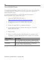
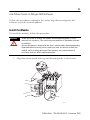
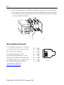
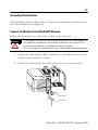
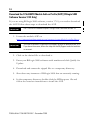
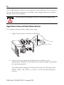
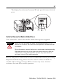
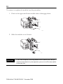
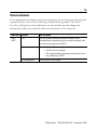
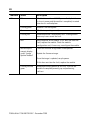
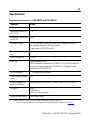
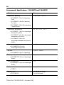
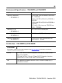
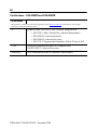
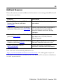
Installation Instructions
ControlLogix EtherNet/IP Communication
Module
Catalog Numbers 1756-EN2TR, 1756-EN3TR
Topic
Page
Important User Information
2
Environment and Enclosure
3
Prevent Electrostatic Discharge
5
North American Hazardous Location Approval
4
About the Module
5
Before You Begin
7
Install the Module
11
Status Indicators
19
Specifications
21
Additional Resources
25
2
Important User Information
Solid state equipment has operational characteristics differing from those of electromechanical
equipment. Safety Guidelines for the Application, Installation and Maintenance of Solid State Controls,
publication (SGI-1.1, available from your local Rockwell Automation sales office or online at
http://www.rockwellautomation.com/literature) some important differences between solid state
equipment and hard-wired electromechanical devices. Because of this difference, and also because of
the wide variety of uses for solid state equipment, all persons responsible for applying this equipment
must satisfy themselves that each intended application of this equipment is acceptable.
In no event will Rockwell Automation, Inc. be responsible or liable for indirect or consequential damages
resulting from the use or application of this equipment.
The examples and diagrams in this manual are included solely for illustrative purposes. Because of the
many variables and requirements associated with any particular installation, Rockwell Automation, Inc.
cannot assume responsibility or liability for actual use based on the examples and diagrams.
No patent liability is assumed by Rockwell Automation, Inc. with respect to use of information, circuits,
equipment, or software described in this manual.
Reproduction of the contents of this manual, in whole or in part, without written permission of Rockwell
Automation, Inc., is prohibited.
Throughout this manual, when necessary, we use notes to make you aware of safety considerations.
WARNING
IMPORTANT
ATTENTION
SHOCK HAZARD
BURN HAZARD
Identifies information about practices or circumstances that can cause an explosion in
a hazardous environment, which may lead to personal injury or death, property
damage, or economic loss.
Identifies information that is critical for successful application and understanding of
the product.
Identifies information about practices or circumstances that can lead to personal
injury or death, property damage, or economic loss. Attentions help you identify a
hazard, avoid a hazard and recognize the consequences.
Labels may be on or inside the equipment (for example, drive or motor) to alert people
that dangerous voltage may be present.
Labels may be on or inside the equipment (for example, drive or motor) to alert people
that surfaces may reach dangerous temperatures.
Publication 1756-IN612B-EN-P - December 2009
3
Environment and Enclosure
ATTENTION
This equipment is intended for use in a Pollution Degree 2 industrial
environment, in overvoltage Category II applications (as defined in IEC
60664-1), at altitudes up to 2000 m (6562 ft) without derating.
This equipment is considered Group 1, Class A industrial equipment according
to IEC/CISPR 11. Without appropriate precautions, there may be difficulties
with electromagnetic compatibility in residential and other environments due
to conducted and radiated disturbances.
This equipment is supplied as open-type equipment. It must be mounted within
an enclosure that is suitably designed for those specific environmental
conditions that will be present and appropriately designed to prevent personal
injury resulting from accessibility to live parts. The enclosure must have
suitable flame-retardant properties to prevent or minimize the spread of flame,
complying with a flame spread rating of 5VA, V2, V1, V0 (or equivalent) if
non-metallic. The interior of the enclosure must be accessible only by the use
of a tool. Subsequent sections of this publication may contain additional
information regarding specific enclosure type ratings that are required to
comply with certain product safety certifications.
In addition to this publication, see:
• Industrial Automation Wiring and Grounding Guidelines, for additional
installation requirements, Allen-Bradley publication 1770-4.1.
• NEMA Standards publication 250 and IEC 60529, as applicable, for
explanations of the degrees of protection provided by different types of
enclosure.
Publication 1756-IN612B-EN-P - December 2009
4
North American Hazardous Location Approval
The following information applies when
operating this equipment in hazardous
locations.
Informations sur l’utilisation de cet
équipement en environnements dangereux.
Products marked "CL I, DIV 2, GP A, B, C, D" are suitable for
use in Class I Division 2 Groups A, B, C, D, Hazardous
Locations and nonhazardous locations only. Each product is
supplied with markings on the rating nameplate indicating
the hazardous location temperature code. When
combining products within a system, the most adverse
temperature code (lowest "T" number) may be used to help
determine the overall temperature code of the system.
Combinations of equipment in your system are subject to
investigation by the local Authority Having Jurisdiction at
the time of installation.
Les produits marqués "CL I, DIV 2, GP A, B, C, D" ne
conviennent qu'à une utilisation en environnements de
Classe I Division 2 Groupes A, B, C, D dangereux et non
dangereux. Chaque produit est livré avec des marquages sur
sa plaque d'identification qui indiquent le code de
température pour les environnements dangereux. Lorsque
plusieurs produits sont combinés dans un système, le code de
température le plus défavorable (code de température le plus
faible) peut être utilisé pour déterminer le code de
température global du système. Les combinaisons
d'équipements dans le système sont sujettes à inspection par
les autorités locales qualifiées au moment de l'installation.
WARNING
EXPLOSION HAZARD • Do not disconnect equipment unless
power has been removed or the
area is known to be nonhazardous.
• Do not disconnect connections to
this equipment unless power has
been removed or the area is known
to be nonhazardous. Secure any
external connections that mate to
this equipment by using screws,
sliding latches, threaded
connectors, or other means
provided with this product.
• Substitution of components may
impair suitability for Class I,
Division 2.
• If this product contains batteries,
they must only be changed in an
area known to be nonhazardous.
AVERTISSEMENT
Publication 1756-IN612B-EN-P - December 2009
RISQUE D’EXPLOSION –
• Couper le courant ou s'assurer
que l'environnement est classé
non dangereux avant de
débrancher l'équipement.
• Couper le courant ou s'assurer
que l'environnement est classé
non dangereux avant de
débrancher les connecteurs. Fixer
tous les connecteurs externes
reliés à cet équipement à l'aide
de vis, loquets coulissants,
connecteurs filetés ou autres
moyens fournis avec ce produit.
• La substitution de composants
peut rendre cet équipement
inadapté à une utilisation en
environnement de Classe I,
Division 2.
• S'assurer que l'environnement est
classé non dangereux avant de
changer les piles.
5
Prevent Electrostatic Discharge
ATTENTION
This equipment is sensitive to electrostatic discharge, which can
cause internal damage and affect normal operation. Follow these
guidelines when you handle this equipment:
•
•
•
•
•
•
Touch a grounded object to discharge potential static.
Wear an approved grounding wriststrap.
Do not touch connectors or pins on component boards.
Do not touch circuit components inside the equipment.
Use a static-safe workstation, if available.
Store the equipment in appropriate static-safe packaging when not in
use.
About the Module
The module provides EtherNet/IP connectivity. Use the tap to support
linear, star, and device-level ring (DLR) topologies. The module is configured
by default to support linear and star topologies. When setting up a DLR,
follow the steps in the Use the Module in a Device-level Ring (DLR) Network
section on page 15 to avoid adversely impacting your network.
Refer to the EtherNet/IP Ring Topology Application Guide,
publication ENET-AP005, for information on setting up EtherNet/IP
network topologies.
Publication 1756-IN612B-EN-P - December 2009
6
Use this figure to identify the external features of the module.
1
2
3
EtherNet/IP TM
10/100 BASE T
10
4
LNK1 LNK2 OK
9
1
2
8
5
7
6
Item
Description
Item
Description
1
Top view
6
Bottom view
2
Rotary switches
7
RJ45 (Ethernet) cable connectors
(on underside of module)
3
Side view
8
Front view
4
Backplane connector
9
USB port
5
MAC ID label (on opposite side
of circuit board)
10
Alphanumeric display and status
indicators
Publication 1756-IN612B-EN-P - December 2009
7
Software Requirements
You must have the following versions of software.
Module
Software
Version
1756-EN2TR
RSLinx Classic
2.55 or later
RSLogix 5000
17.0x (supports revision 2 of module firmware only)
If you are using version 17.01 of RSLogix 5000 software, you need to download the
add-on-profile. Download it from
http://www.rockwellautomation.com/support/controlflash/LogixProfiler.asp
or
18 or later (supports revision 2 and later revisions of module firmware)
1756-EN3TR
RSLinx Classic
2.56 or later
RSLogix 5000
18 or later
Before You Begin
Before you install the module, you must install and connect a ControlLogix
chassis and power supply.
1
2
Item
Description
1
Power supply
2
1756-A4 chassis
20805-M
Publication 1756-IN612B-EN-P - December 2009
8
To install these products, refer to these publications.
Chassis Type
Chassis Installation Instructions
Power Supply
Power Supply Installation
Instructions
1756-A4/B
1756-A7/B
1756-A10/B
1756-A13/B
Publication 1756-IN080
1756-PA72/C,
1756-PB72/B,
1756-PA75/B,
1756-PB75/B
Publication 1756-IN613
Determine Module Slot Location
Install the module in any slot in the ControlLogix chassis. You can install
multiple 1756-EN2TR or 1756-EN3TR modules in the same chassis. The
following figure shows chassis slot numbering in a 4-slot chassis. Slot 0 is the
first slot and is always the leftmost slot in the rack.
3
5
4
6
1
2
Item
Description
1
Power supply
2
Chassis
3
Slot 0
4
Slot 1
5
Slot 2
6
Slot 3
20806
Set the Network Address
The module is shipped with the rotary switches set to 999 and BOOTP
enabled. You can set the network Internet Protocol (IP) address three ways.
• Use the rotary switches on the top of the module.
• Use a BOOTP server or Dynamic Host Configuration Protocol
(DHCP) server.
• Use Rockwell Automation RSLinx Classic or RSLogix 5000 software.
Publication 1756-IN612B-EN-P - December 2009
9
Use the Rotary Switches
Item
2
1
Description
1
Front of module
2
Top of module
3
Rotary switches
31587
3
The module reads the rotary switches first to determine if they are set to a
valid number for the last portion of the IP address. Valid numbers range from
001…254.
When the switches are set to a valid number, the module’s IP address is
192.168.1.xxx (where xxx represents the number set on the switches). The
module’s subnet mask is 255.255.255.0 and the gateway address is set to
0.0.0.0.
The module does not have a host name assigned, nor does it use any Domain
Name System when using the rotary switch settings.
1. To reset the module to its initial out-of-the-box settings, reset the
switches to 888 and cycle power.
IMPORTANT
Do not use the 888 switch setting during normal module operation.
2. After cycling power with the switches set to 888, remove the module
and set the switches to their final value.
The software configuration determines the IP address when you set
the rotary switches to:
• a value other than 888.
• the valid IP address values 001…254.
Publication 1756-IN612B-EN-P - December 2009
10
Use a DHCP/BOOTP Server
If you do not have a large computer that can act as a boot server, download
our DHCP/BOOTP software so you can use a personal computer as a
DHCP/BOOTP server.
To set the network address by using the Rockwell Automation
DHCP/BOOTP server, follow these steps.
1. Access the DHCP/BOOTP utility at
http://www.ab.com/networks/ethernet/bootp.html.
2. Download the version 2.3.2 DHCP/BOOTP utility.
3. Extract the zipped files to a temporary directory.
4. In the temporary directory, double-click setup.exe to install the
DHCP/BOOTP utility.
5. Run the utility.
6. Refer to the following chart, which describes what happens next,
depending on whether DHCP/BOOTP is enabled on the module.
If DHCP/BOOTP is
The module
Enabled
Asks for an address from a DHCP/BOOTP server. The server
also assigns other Transport Control Protocol (TCP) parameters.
Not enabled
Uses the IP address (along with other TCP configurable
parameters) stored in nonvolatile memory.
Publication 1756-IN612B-EN-P - December 2009
11
Use RSLinx Classic or RSLogix 5000 Software
Follow the procedures outlined in the online help that accompanies this
software to set the network address.
Install the Module
To install the module, follow this procedure.
WARNING
When you insert or remove the module while backplane power is on, an
electrical arc can occur. This could cause an explosion in hazardous location
installations.
Be sure that power is removed or the area is nonhazardous before proceeding.
Repeated electrical arcing causes excessive wear to contacts on both the
module and its mating connector. Worn contacts may create electrical
resistance that can affect module operation.
1. Align the circuit board with top and bottom guides in the chassis.
31588-M
Publication 1756-IN612B-EN-P - December 2009
12
2. Slide the module into the chassis, making sure the module backplane
connector properly connects to the chassis backplane and noting that
the module is properly installed when it is flush with the power supply
or other installed modules.
31589-M
Wire the Ethernet Connector
Use an RJ45 connector to connect
to the EtherNet/IP network. Wire
the connector as shown.
For detailed EtherNet/IP
connection information, see the
EtherNet/IP Media Planning and
Installation Manual, available from
the Open DeviceNet Vendor
Association (ODVA) at
http://www.odva.org.
8 ------ NC
7 ------ NC
6 ------ RD5 ------ NC
4 ------ NC
3 ------ RD+
2 ------ TD1 ------ TD+
Publication 1756-IN612B-EN-P - December 2009
8
1
RJ 45
13
Grounding Considerations
The grounding and bonding must be of equal potential between all devices in
the communication coverage area.
Connect the Module to the EtherNet/IP Network
Follow this procedure to connect the module to the network.
WARNING
If you connect or disconnect the communication cable with power applied to
this module or any device on the network, an electrical arc can occur. This
could cause an explosion in hazardous location installations.
Be sure that power is removed or the area is nonhazardous before proceeding.
1. Attach the cable with the RJ45 connector to the Ethernet port on the
bottom of the module as shown.
2. Attach the other end of the cable to the devices in your network.
Publication 1756-IN612B-EN-P - December 2009
14
Download the 1756-EN2TR Module Add-on Profile (AOP) [RSLogix 5000
Software Version 17.01 Only]
If you are using RSLogix 5000 software, version 17.01, you need to download
the AOP. Follow these steps to download the AOP.
IMPORTANT
The 1756-EN3TR module requires RSLogix 5000 software version 18.
1. Locate the module AOP on
http://www.rockwellautomation.com/support/controlflash/LogixProfiler.as.
IMPORTANT
You need a Rockwell Automation MySupport account to download the AOP.
If you do not have one, follow the steps on the MySupport website to obtain
an account.
2. Click on the desired file to download it.
3. Enter your RSLogix 5000 software serial number and click Qualify for
Update.
4. Download and extract the zipped files to a temporary directory.
5. Shut down any instances of RSLogix 5000 that are currently running.
6. In the temporary directory, double-click the MPSetup.exe file and
follow the onscreen instructions to install the AOP.
Publication 1756-IN612B-EN-P - December 2009
15
Use the Module in a Device-level Ring (DLR) Network
The module is configured by default to be used in a linear or star topology, or
as a ring node in a DLR network. Follow these steps to use the module in a
DLR network as a ring supervisor.
1. If you are using the unit as a ring supervisor, follow the procedures
outlined in the online help that accompanies RSLinx or RSLogix 5000
software to enable the ring supervisor function with this software.
IMPORTANT
• Make sure at least one ring supervisor is present before connecting the
last link of a device-level ring network and physically closing the ring.
• Do not connect nodes that do not support a device-level ring as
members of the ring.
2. Refer to the EtherNet/IP Ring Topology Application Guide,
publication ENET-AP005, for information on setting up
EtherNet/IP network topologies.
Connect to the Module via the USB Port
WARNING
The USB port is intended for temporary local programming purposes only and
not intended for permanent connection. If you connect or disconnect the USB
cable with power applied to this module or any device on the USB network, an
electrical arc can occur. This could cause an explosion in hazardous location
installations.
Be sure that power is removed or the area is nonhazardous before proceeding.
A Samtec Inc. RSP-119350 USB cable is required to maintain hazardous
location certifications.
The module has a USB device port that uses a series B receptacle. To use the
USB port, you must have RSLinx Classic software, version 2.55 or later,
installed on your computer.
Publication 1756-IN612B-EN-P - December 2009
16
Use a USB cable to connect your computer to the USB port. The connection
lets you download programs to controllers and configure Ethernet modules
directly from your computer.
ATTENTION
The USB cable is not to exceed 3.0 m (9.84 ft) and must not contain hubs.
Apply Chassis Power and Check Status Indicators
To complete this procedure, follow these steps.
1. Apply chassis power as shown in the figure.
2. Check the power supply and module status indicators and
alphanumeric display to determine that the power supply and module
are operating properly.
The alphanumeric display should cycle through the following states:
TEST - PASS - OK - REV x.x, where x.x is the module’s firmware
revision.
Publication 1756-IN612B-EN-P - December 2009
17
The display then alternates between OK and port link status for both
ports.
TM
10/100 BASE T
LNK1 LNK2 OK
LNK1 LNK2 OK
Install or Remove the Module Under Power
You can install or remove this module while chassis power is applied.
WARNING
When you insert or remove the module while backplane power is on, an
electrical arc can occur. This could cause an explosion in hazardous location
installations.
Be sure that power is removed or the area is nonhazardous before proceeding.
Repeated electrical arcing causes excessive wear to contacts on both the
module and its mating connector. Worn contacts may create electrical
resistance that can affect module operation.
Be sure that power is removed or the area is nonhazardous before proceeding.
Repeated electrical arcing causes excessive wear to contacts on both the
module and its mating connector. Worn contacts may create electrical
resistance that can affect module operation.
Publication 1756-IN612B-EN-P - December 2009
18
To remove or replace the module, use this procedure.
1. Push on the upper and lower module tabs to disengage them.
31590-M
2. Slide the module out of chassis.
31591-M
IMPORTANT
If you want to replace an existing module with an identical one, and you
want to resume identical system operation, you must install the new module
in the same slot.
Publication 1756-IN612B-EN-P - December 2009
19
Status Indicators
If the alphanumeric display and status indicators do not sequence through the
expected states, refer to the following troubleshooting tables. The three
bi-color (red/green) status indicators on the module provide diagnostic
information about the module and its connections to the network.
Indicator
Status
Description
LNK1,
LNK2
Off
No link, or port administratively disabled, or port
disabled due to rapid ring faults or partial network fault
on active ring supervisor (LNK2).
Green
One of these conditions exists:
• A link exists on the port.
• The ring network is operating normally on active
ring supervisor (LNK2).
Flashing green
Activity exists on the port
Publication 1756-IN612B-EN-P - December 2009
20
Indicator
Status
Description
OK
Off
Module does not have 24V DC power. Verify that there
is chassis power and the module is completely inserted
into chassis and backplane.
Flashing green
Module is not configured.
Green
Module is operating correctly.
Flashing red
Module detected a recoverable fault. A configuration
error may have caused the fault.
Red
Recycle power to the module. If this does not clear the
fault, replace the module. Check the module
configuration and, if necessary, reconfigure the module.
Red and alphanumeric display
scrolls 'Image
Update Needed'
The main firmware image needs to be updated.
Update the firmware image.
Once the image is updated, recycle power.
If this does not clear the fault, replace the module.
Flashing red and
green
Module performing power-up self-test. Wait for the
module to complete powering up and performing
self-test.
Publication 1756-IN612B-EN-P - December 2009
21
Specifications
Technical Specifications - 1756-EN2TR and 1756-EN3TR
Attribute
Value
Module location
Any slot in the ControlLogix chassis
Backplane current (mA)
at 5.1V DC
1A
Backplane current (mA)
at 24V DC
3 mA
Isolation voltage
30 V (continuous), Basic Insulation Type, Ethernet to system
No isolation between USB and system
Type tested at 853V AC for 60 s
Power consumption,
max
5.1 W
Power dissipation
5.1 W
Wire size
Ethernet connections:
RJ45 connector according to IEC 60603-7, 2 or 4 pair Category 5e
minimum cable according to TIA 568-B.1 or Category 5 cable
according to ISO/IEC 24702.
Wiring category
1 - on communication ports(1)
North American temp
code
T4A
Recommended USB
cable for USB port
For hazardous environments, Samtec cable, PN RSP-119350
USB port
USB 1.1
USB device,
USB series B receptacle
Enclosure type rating
None (open-style)
(1)
Use this Conductor Category information for planning conductor routing.
Refer to Industrial Automation Wiring and Grounding Guidelines, publication 1770-4.1.
Publication 1756-IN612B-EN-P - December 2009
22
Environmental Specifications - 1756-EN2TR and 1756-EN3TR
Attribute
Value
Temperature, operating
• IEC 60068-2-1 (Test Ad, Operating
Cold)
• IEC 60068-2-2 (Test Bd, Operating
Dry Heat)
• IEC 60068-2-14 (Test Nb, Operating
Thermal Shock)
0…60 °C (32…140 °F)
Temperature, nonoperating
• IEC 60068-2-1 (Test Ab, Unpackaged
Nonoperating Cold)
• IEC 60068-2-2 (Test Bb, Unpackaged
Nonoperating Dry Heat)
• IEC 60068-2-14 (Test Na,
Unpackaged Nonoperating Thermal
Shock)
-40…85 °C (-40…185 °F)
Relative humidity
• IEC 60068-2-30 (Test Db,
Unpackaged Damp Heat)
5…95% noncondensing
Vibration
• IEC 60068-2-6 (Test Fc, Operating)
2 g @ 10…500 Hz
Shock, operating
• EC 60068-2-27 (Test Ea, Unpackaged
Shock)
30 g
Shock, nonoperating
• IEC 60068-2-27 (Test Ea, Unpackaged
Shock)
50 g
Emissions
• CISPR 11
Group 1, Class A
Immunity, ESD
• IEC 61000-4-2
6 kV contact discharges
8 kV air discharges
Publication 1756-IN612B-EN-P - December 2009
23
Environmental Specifications - 1756-EN2TR and 1756-EN3TR
Attribute
Value
Immunity, radiated RF
• IEC 61000-4-3
10V/m with 1 kHz sine-wave 80%AM from
80…2000 MHz
10V/m with 200 Hz 50% Pulse 100%AM at
900 MHz
10V/m with 200 Hz 50% Pulse 100%AM at
1890 MHz
3V/m with 1 kHz sine-wave 80%AM from
2000…2700 MHz
Immunity, EFT/B
• IEC 61000-4-4
±3 kV at 5 kHz on Ethernet port
Immunity, surge transient
• IEC 61000-4-5
±2 kV line-earth(CM) on Ethernet port
Immunity, conducted RF
• IEC 61000-4-6
10V rms with 1 kHz sine-wave 80%AM
from 150 kHz…80 MHz
Certifications - 1756-EN2TR and 1756-EN3TR
Certification
Value
When product is marked. See the Product Certification link at http://www.ab.com for Declarations of Conformity,
Certificates, and other certification details
c-UL-us
UL Listed Industrial Control Equipment, certified for US and Canada.
See UL File E65584.
UL Listed for Class I, Division 2 Group A,B,C,D Hazardous Locations,
certified for U.S. and Canada. See UL File E194810.
FM
FM Approved Equipment for use in Class I Division 2 Group A,B,C,D
Hazardous Locations
Publication 1756-IN612B-EN-P - December 2009
24
Certifications - 1756-EN2TR and 1756-EN3TR
Certification
Value
When product is marked. See the Product Certification link at http://www.ab.com for Declarations of Conformity,
Certificates, and other certification details
CE
European Union 2004/108/EC EMC Directive, compliant with:
• EN 61326-1; Meas./Control/Lab., Industrial Requirements
• EN 61000-6-2; Industrial Immunity
• EN 61000-6-4; Industrial Emissions
• EN 61131-2; Programmable Controllers (Clause 8, Zone A & B)
C-Tick
Australian Radiocommunications Act, compliant with:
AS/NZS CISPR 11; Industrial Emissions
EtherNet/IP
ODVA conformance tested to EtherNet/IP specifications
Publication 1756-IN612B-EN-P - December 2009
25
Additional Resources
These documents contain additional information concerning related Rockwell
Automation products.
Resource
Description
EtherNet/IP Modules in Logix5000 Control
Systems User Manual, publication
ENET-UM001
Provides details about how to configure
your module.
EtherNet/IP Embedded Switch Technology
Application Guide, publication ENET-AP005
Provides information about using products
with embedded switch technology to
construct networks with linear and ring
topologies.
EtherNet/IP Industrial Protocol White Paper,
publication ENET-WP001
Describes how to implement services and
data objects on a TCP/UDP/IP based
Ethernet network.
Industrial Automation Wiring and Grounding
Guidelines, publication 1770-4.1
Provides general guidelines for installing a
Rockwell Automation industrial system.
Product Certifications website,
http://www.ab.com
Provides declarations of conformity,
certificates, and other certification details.
You can view or download publications at
http://www.rockwellautomation.com/literature. To order paper copies of
technical documentation, contact your local Rockwell Automation distributor
or sales representative.
Publication 1756-IN612B-EN-P - December 2009
26
Notes:
Publication 1756-IN612B-EN-P - December 2009
27
Notes:
Publication 1756-IN612B-EN-P - December 2009
Rockwell Automation Support
Rockwell Automation provides technical information on the Web to assist you in using
its products. At http://support.rockwellautomation.com, you can find technical
manuals, a knowledge base of FAQs, technical and application notes, sample code and
links to software service packs, and a MySupport feature that you can customize to
make the best use of these tools.
For an additional level of technical phone support for installation, configuration, and
troubleshooting, we offer TechConnect support programs. For more information,
contact your local distributor or Rockwell Automation representative, or visit
http://support.rockwellautomation.com.
Installation Assistance
If you experience a problem within the first 24 hours of installation, please review the
information that's contained in this manual. You can also contact a special Customer
Support number for initial help in getting your product up and running.
United States
1.440.646.3434
Monday – Friday, 8 a.m. – 5 p.m. EST
Outside United States
Please contact your local Rockwell Automation representative for any technical support
issues.
New Product Satisfaction Return
Rockwell Automation tests all of its products to ensure that they are fully operational
when shipped from the manufacturing facility. However, if your product is not
functioning and needs to be returned, follow these procedures.
United States
Contact your distributor. You must provide a Customer Support case number (call the
phone number above to obtain one) to your distributor in order to complete the return
process.
Outside United States
Please contact your local Rockwell Automation representative for the return procedure.
Allen-Bradley, ControlLogix, Rockwell Automation, RSLinx, RSLogix 5000, and TechConnect are trademarks of
Rockwell Automation, Inc.
Trademarks not belonging to Rockwell Automation are property of their respective companies.
Publication 1756-IN612B-EN-P - December 2009
Supersedes Publication 1756-IN612A-EN-P - May 2009
PN-57934
Copyright © 2009 Rockwell Automation, Inc. All rights reserved. Printed in the U.S.A.