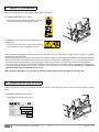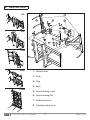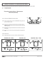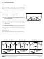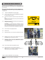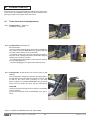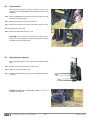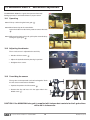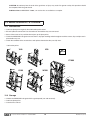
1
MANUBAL
V40
V50
V500
W500
V7000
User Manual
Read carefully before operating
the Manubal bale grab
UK 364188 AC - 0314
Original instructions
Dear user,
We thank you for placing your trust in our product and hope you will find your MX MANUBAL satisfactory in every
way.
Taking a few minutes to read this manual will enable you to use the capabilities of your MX MANUBAL to the full,
prolong its service life and ensure safe operation.
The MANUBAL user manual before you is an important document, please retain it in order to be able to refer to it
if required. Make it available to any other users and hand it over it to any new owner in the event of your MX
MANUBAL being sold on.
The illustrations and technical data shown in this document might not match your MX MANUBAL bale grab
exactly, operating conditions will nevertheless remain the same.
CONTENTS
1. SAFETY RULES
4
2. SAFETY STICKERS
5
3. IDENTIFICATION PLATE
5
4. DESCRIPTION
6
5. HITCHING/UNHITCHING THE MANUBAL BALE GRAB
7
6. GRAB OPENING / CLOSING ADJUSTMENT
8
7. WRAPPED BALE GRAB KIT
10
8. LOWER TINE KIT
11
9. MANUBAL V50: changing grab setting13
10. MANUBAL W500: 2nd bale sensor adjustment14
11. MANUBAL V7000: Using the lower tines15
12. MAINTENANCE / STORAGE
16
13. TECHNICAL SPECIFICATIONS
17
1. SAFETY RULES
The tractor/loader or telescopic handler/MANUBAL bale grab combination must only be operated by trained and experienced
personnel.
— For your complete safety and that of others, strict compliance with the hitching and unhitching procedure for the
MANUBAL bale grab is required (chapter 5 of this manual).
— Only control the MANUBAL bale grab from the driver’s seat. Keep operating the controls until movements stop.
— Do not leave the driver’s seat without stopping all control movements.
— All personnel must be kept away from the area in which the loader or telescopic handler - MANUBAL bale grab combination is
moving while it is in operation.
— Never pass under a raised bale. Never use the MANUBAL bale grab to push a bale.
— Carrying or lifting personnel using the MANUBAL bale grab is forbidden. Never stand or pass under the load.
— Before any operation, the user must ensure that the MANUBAL bale grab is in proper working order and can be used in
complete safety. He must also check and ensure that the tractor-loader-MANUBAL bale grab combination is stable by fitting
a counterweight to the back of the tractor. This should ensure that 20% of gross weight remains on the rear axle of the tractor
for optimum safety while travelling and working.
— When travelling on the road it is imperative that the regulations governing use on the public highway be observed (size,
implement markings, etc.) Protruding items such as tine ends must be protected or stowed (grab closed, lower tine kit
retracted).
— Take great care when operating at height in order to avoid catching any items (electric power or telephone lines, guttering, roof
trusses, etc.).
— Whenever the tractor or telescopic handler is stopped momentarily or for an extended period, the engine must be shut down
and the MANUBAL bale grab lowered.
— When not in use, protruding items such as tine ends must be protected or stowed (grab closed, lower tine kit retracted).
— Check periodically to ensure that safety pins and bolts are in place. Do not replace them with any other items such as: nails,
wire, etc.
— Any adjustment on the MANUBAL bale grab (ram position, tines in fixed or floating position, etc.) must be carried out after the
MANUBAL bale grab has been lowered to the ground and the tractor or telescopic handler engine shut down (grab in lower setting
for the MANUBAL V50 unit).
— Any work involving fault tracing (diagnostics) and/or disassembly of parts may only be undertaken by a skilled technician who
will start with an assurance that the work will be carried out in complete safety for himself and his surroundings.
Caution !
— Check hoses for length and routing in all configurations (fully crowded, fully dumped, etc.) before first use.
— The MANUBAL bale grab is designed to withstand a maximum operating pressure of 210 bar. Above this pressure, the
MANUBAL bale grab will require to be fitted with a pressure limiter.
— Any instance of a MANUBAL bale grab being fitted which ignores the recommendations in the MX price list in force on the date
of purchase will void MX warranty on the entire supply.
— Any modification to any part of the MX supply (rams, grab, tines, crank, etc.) or use of a component installed on the MANUBAL
bale grab which has not originated from MX will void MX warranty on the entire MX supply.
— Use only genuine MX spare parts. Do not modify your MANUBAL bale grab yourself or have it modified by anyone else, without
first requesting written authorisation from MX. Failure to comply with these rules may render your MANUBAL bale grab
hazardous. In the event of damage or injury, MX shall not be held responsible in any way.
— Warranty cover will cease immediately in the event of failure to observe the standards and instructions for use and maintenance
of the MANUBAL bale grab as stipulated in the user manual.
THE INSTALLER SHALL BE FULLY LIABLE FOR ANY FITMENT ON A LOADER OTHER THAN MX OR A TELESCOPIC
HANDLER WHICH HAS NOT BEEN RECOMMENDED BY MX.
• 19, rue de Rennes • BP 83221 • F - 35690 ACIGNÉ
4
Modification reserved
2. SAFETY STICKERS
Ensure the labels are clean and legible; replace them if damaged.
1. Location: MANUBAL frame carrier
— Familiarise yourself with the safety rules in the user
manual before using or working on the unit.
1
OK
.............g
er
328462
..
...............
Rennes
de
rue ACIGNÉ
19, 35690
F/ Typ
...........k
/Model
/ Seriennumm
Type
série
de number
N˚
Serial à vide
weight
Poids
Unloaded
Leergewicht
516154
OK
516154
2. Location: Lower tine kit carrier (optional) or on
V7000 frame.
2
— Familiarise yourself with the safety rules in the user
manual before using or working on the unit.
MX implements are designed to offer the operator of the prime mover to which they are fitted optimum angles for crowding
and dumping at ground level.
Before handing over to the operator, the installer must check that there is no possibility of interference occurring between the
implement which has been fitted and other components of the machine (tyres, mudguards, etc.), as a result of the maximum
travel of the implement installed, when the telescopic handler boom positions the implement closest in to the machine.
In the event of the aggregation of positional conditions of the implement and the boom leading to interference, the installer is
to notify the operator and provide him with instructions on how to prevent such interference. In general it is sufficient to
operate with the boom extended by at least 0.5 m.
MX cannot be held liable for any damage or accidents which might result from impacts caused by this.
3. IDENTIFICATION PLATE
Identification details are to be passed on to your dealer with any request for spare parts or service work. Its location is shown
below.
3. Location: MANUBAL frame carrier
— MANUBAL identification data plate
19, rue de Rennes F - 35690 ACIGNÉ
Désignation/
Designation
Type / Model / Typ
Poids à vide
Unloaded weight / Leergewicht
kg
.............g
er
328462
..
...............
Rennes
de
rue ACIGNÉ
19, 35690
F/ Typ
...........k
/Model
/ Seriennumm
Type
série
de number
N˚
Serial à vide
weight
Poids
Unloaded
Leergewicht
Année / Year
OK
328462
N˚ de série
Serial number
Seriennummer
• 19, rue de Rennes • BP 83221 • F - 35690 ACIGNÉ
516154
3
5
Modification reserved
4. DESCRIPTION
V40
2
MANUBA
4
8
3
L
V50
6
7
L
MANUBA
5
V500
MANUBA
1
L
W500
1. Vertical mast
2. Grab
MANUBA
L
3. Tine
4. Ram
V7000
5. Synchronising crank
6. Synchronising link
7. Rod-end ram pin
8. Cylinder-end ram pin
• 19, rue de Rennes • BP 83221 • F - 35690 ACIGNÉ
6
Modification reserved
5. HITCHING/UNHITCHING THE MANUBAL BALE GRAB
5.1
HITCHING THE MANUBAL BALE GRAB
5.1.1 Hook the self-centring V notches into the MANUBAL hitch bar Fig. 1 (for telescopic handlers, refer to the manufacturer’s
user manual).
5.1.2 Position yourself on the right-hand side and lock manually Fig. 2.
5.1.3 Crowd back to check that the MANUBAL is being held correctly Fig. 3.
5.1.4 Operate each moving component to its fullest extent in each direction to check the hydraulic system is free from leaks and
the hoses are routed correctly.
1
2
Position for locking the
MANUBAL bale grab
MX loaders before May 2013
3
MX loaders after May 2013
364142_4
Push with your foot
Caution, you may be crushed
5.2
UNHITCHING THE MANUBAL BALE GRAB
5.2.1 Remove the MANUBAL unit with the grab open (ram rod
retracted).
5.2.2 Release the hydraulic pressure and unhitch.
_5
142
364
CAUTION: for MANUBAL bale grabs fitted with lower tines, these should be in the park position
(see chapters 8 and 10).
• 19, rue de Rennes • BP 83221 • F - 35690 ACIGNÉ
7
Modification reserved
6. GRAB OPENING / CLOSING ADJUSTMENT
The extent of opening and closing of the grab can be adjusted to match the type of bale being handled.
6.1
ROUND BALES
This setting enables 0.90m to 1.80m diameter
bales to be picked up.
6.1.1 Position the MANUBAL bale grab upright.
6.1.2 Open the grab halfway. Lower the MANUBAL bale grab to the
ground. Stop the engine.
6.1.3 Remove the clip from the rod-end ram pin and remove the pin.
Note: the screw on the pin flat acts to prevent rotation and need
not be removed.
364187_10
6.1.4 Position the ram opposite the hole for the round bale setting. See
table below.
6.1.5 Insert the pin as well as the synchronising link in the appropriate
hole.
6.1.6 Refit the clip.
6.1.7 Repeat operations 6.1.3 to 6.1.6 for the cylinder-end ram pin.
MANUBAL V40 - W500
• 19, rue de Rennes • BP 83221 • F - 35690 ACIGNÉ
MANUBAL V50
8
MANUBAL V500 - V7000
Modification reserved
6.2
RECTANGULAR BALE
With the grab open, the tines do not extend beyond the
vertical mast. Rectangular bale pick-up is more effective.
6.2.1 Position the MANUBAL bale grab upright.
6.2.2 Open the grab halfway. Lower the MANUBAL bale grab to the
ground. Stop the engine.
364187_11
6.2.3 Remove the clip from the rod-end ram pin and remove the pin.
Note: the screw on the pin flat acts to prevent rotation and need
not be removed.
6.2.4 Position the ram opposite the hole for the rectangular bale
setting. See table below.
6.2.5 Insert the pin as well as the synchronising link in the appropriate
hole.
6.2.6 Refit the clip.
6.2.7 Repeat operations 6.2.3 to 6.2.6 for the cylinder-end ram pin.
MANUBAL V40 - W500
• 19, rue de Rennes • BP 83221 • F - 35690 ACIGNÉ
MANUBAL V50
9
MANUBAL V500 - V7000
Modification reserved
7. WRAPPED BALE GRAB KIT
This kit converts your MANUBAL unit into a round wrapped bale
grab*. The conversion is very simple and is accomplished in just
a few seconds.
Wrapped bale grab opening / closing adjustment
The adjustment is carried out using the holes provided for round
wrapped bales.
7.1
Position the MANUBAL bale grab upright.
7.2
Open the grab halfway. Lower the MANUBAL bale grab to
the ground. Stop the engine.
7.3
Remove the clip from the rod-end ram pin and remove the
pin.
Note: the screw on the pin flat acts to prevent rotation and
need not be removed.
7.4
Position the ram opposite the hole for the wrapped bale
setting. See drawing 1 .
CAUTION: the synchronising links should be removed
from the MANUBAL bale grab when it is used for wrapped
bales, which allows the 2 grab arms to float.This enhances
effectiveness and safety when stacking bales contiguously.
7.5
Insert the pin in the appropriate hole.
7.6
Refit the clip.
7.7
Repeat operations 7.3 to 7.6 for the cylinder-end ram pin.
7.8
Position the first side of the wrapped bale grab kit
(U-section) against the grab tine carrier.
7.9
Position the other side of the wrapped bale grab kit
(O-section) opposite the hole provided for this purpose
in the MANUBAL grab.
1
515755
U
O
U
O
7.10
Insert the pin and the clip supplied in the kit.
7.11
Repeat operations 7.8 to 7.10 for the other kit.
Note: the kit is not handed as regards assembly. It is
identical for the left and right-hand sides.
* Option available on MANUBAL V40, V50, W500.
• 19, rue de Rennes • BP 83221 • F - 35690 ACIGNÉ
10
Modification reserved
8. LOWER TINE KIT
The lower tine kit* is recommended for handling rectangular bales.
It also makes your MANUBAL bale grab even more effective when
picking up round or rectangular bales in the field.
8.1
Three lower tine kit configurations
8.1.1 Configuration 1 : fixed tines.
Traditional configuration.
8.1.2 Configuration 2: floating tines.
Several benefits:
- It eases withdrawal of the tines when setting a bale down.
All it needs is to tilt the MANUBAL bale grab forward with
the vertical mast and the tines will withdraw.
- It prevents unnecessary pressure from being exerted on
the bales when stacking and also the loader from dropping
abruptly once the tines are clear.
- Its 2 independently floating tines mean effective stacking,
even on sloping ground.
- It reduces dragging on the ground thus reducing wear.
8.1.3 Configuration 3: fold-up tines for road use (only on MX
loaders).
This configuration enables the benefits of configuration 2
(floating tines) to be enjoyed at the same time as being able
to fold up the tines when travelling on the road.
All this requires is to crowd the MANUBAL bale grab back
and to raise the loader. The tines fold up automatically.
CAUTION:
Check that the overall height of the assembly is completely
safe for travelling.
Do not close the grab while the MANUBAL bale grab is
tilted.
* Option available on MANUBAL V40, V50, V500, W500
• 19, rue de Rennes • BP 83221 • F - 35690 ACIGNÉ
11
Modification reserved
8.2
Park position
When the lower tine kit is not being used the tines can be
stowed away in the MANUBAL bale grab without affecting its
operation.
8.2.1 Place the MANUBAL bale grab on the ground with the grab
closed and stop the engine.
8.2.2 Remove the clip then the pin from the tine.
8.2.3 Remove the tine from its location and slide it into the carrier.
8.2.4 Refit the pin and the clip.
8.2.5 Repeat the procedure for the 2nd tine.
CAUTION: do not bump into the ends of the grab tines as
injury may result. For greater safety, this operation should be
completed with the grab closed.
8.3
Adjusting tine spacing
Spacing between tines may be adjustable according to bale
size.
8.3.1 Slacken off the nuts on the tine carrier clamp.
8.3.2 Slide the carrier along the frame.
8.3.3 Retighten the clamp observing the correct tightening torque
(174 Nm).
Additional lower tine on MANUBAL V500, a 3rd tine is
available as an option.
• 19, rue de Rennes • BP 83221 • F - 35690 ACIGNÉ
12
Modification reserved
9. MANUBAL V50: changing grab setting
The MANUBAL V50 has 2 vertical grab settings (lower setting and
raised setting). This enables 5 round bales to be stacked using the
raised setting. A specific feature of the MANUBAL V50 is that the
switch from the lower setting to the raised setting (and vice versa)
may be operated without leaving the cab and without an additional
hydraulic function on the loader.
9.1
Pick up a bale.
9.2
Set the MANUBAL V50 horizontal.
9.3
Move the tractor forward towards the stack that is being
built up in order to operate the pusher, this unlocks the grab
1 .
9.4
Tilt the MANUBAL V50 forward in order to cause the grab
to slide under the force of gravity, this locks the grab in the
raised setting 2 .
9.5
Crowd the MANUBAL V50 back and set the bale down on
top of the stack 3 .
1
2
3
To return the grab to the lower setting.
9.6
Set the MANUBAL V50 horizontal.
9.7
Operate the pusher against a stacked bale, this unlocks the
grab.
9.8
Crowd the MANUBAL V50 back in order to cause the grab
to slide under the force of gravity, this locks the grab in the
lower setting.
CAUTION: keep all personnel away from the area in which the loader - MANUBAL V50
combination is moving while it is in operation.
• 19, rue de Rennes • BP 83221 • F - 35690 ACIGNÉ
13
Modification reserved
10. MANUBAL W500: 2nd bale sensor adjustment
The MANUBAL W500 has 2 grabs that operate alternately.
Picking up 2 bales is achieved without any repeat action.
10.1 Operating
10.1.1 Pick up a bale using the lower grab 1 .
10.1.2 Move forward up to the second bale.
Lower the loader in order for the probe to contact the bale
2 .
1
10.1.3 Without releasing the first bale, pick up the second bale by
closing the upper grab 3 .
2
3
10.2 Adjusting the detector
The 2nd bale sensor is adjustable for sensitivity.
— Slacken off the 2 screws 1 .
— Adjust the hydraulic block by altering its position.
1
— Retighten the 2 screws.
10.3 Overriding the sensor
The 2 grabs can be operated synchronised together. To do
this the sensor needs to be overridden.
— Operate the probe to its fullest extent 1 .
1
— Remove the clip and insert it in the upper hole in the
drilled screw 2 .
2
CAUTION: if the MANUBAL bale grab is supplied with independent controls for the 2 grabs there
will be no 2nd bale sensor.
• 19, rue de Rennes • BP 83221 • F - 35690 ACIGNÉ
14
Modification reserved
11. MANUBAL V7000: Using the lower tines
The MANUBAL V7000 features 3 lower tines particularly suited to
handling rectangular bales. Its tines may be fixed, floating or folding.
1
11.1 Three configurations
11.1.1 Configuration 1: fixed tines.
Traditional configuration
11.1.2 Configuration 2 : floating tines.
Several benefits:
- It eases withdrawal of the tines when setting a bale down.
All it needs is to tilt the MANUBAL bale grab forward with the
vertical mast and the tines will withdraw.
- It prevents unnecessary pressure from being exerted on the
bales when stacking and above all the telescopic handler
boom dropping abruptly once the tines are clear.
- It reduces dragging on the ground and thus reducing wear.
2
CAUTION: do not close the grab while the MANUBAL bale
grab is tilted.
11.1.3 Configuration 3 : fold-up tines for road use.
1. Open the grab to its fullest extent (ram in rectangular bale
setting, see chapter 6.2). Stop the engine.
2. Remove clips and pins.
3. Fold up the tines and carrier assembly.
4. While holding this position, refit the pins and clips in the
holes provided for this purpose.
3
CAUTION: do not close the grab with the tines folded up.
11.2 Park position
When the lower tines are not being used, they can be stowed
away in the MANUBAL bale grab without affecting its
operation.
11.2.1 Place the MANUBAL bale grab on the ground with the grab
closed and stop the engine.
11.2.2 Remove the clip then the pin from the tine.
11.2.3 Remove the tine from its location and slide it into the carrier.
11.2.4 Refit the pin and the clip.
11.2.5 Repeat the procedure for the 2nd and 3rd tine.
• 19, rue de Rennes • BP 83221 • F - 35690 ACIGNÉ
15
Modification reserved
CAUTION: do not bump into the ends of the grab tines as injury may result. For greater safety, this operation should
be completed with the grab closed.
Additional tine on MANUBAL V7000, a 4th and 5th tine are available as an option.
12. MAINTENANCE / STORAGE
12.1 Maintenance
— Lubricate pivot points regularly. See lubrication points below.
— Ensure hydraulic connections are cleaned each time before they are connected.
— See to it that straw or hay residues do not jam up the pivot points.
— Check the MANUBAL bale grab to ensure that it is in proper working order throughout and that screws, clips and pins are in
place before any use.
— Check the condition of the wear bushes and replace them before they are fully worn.
Lubrication points:
V40
V50
V7000
V500
W500
12.2 Storage
— Unhitch the MANUBAL bale grab with the grab opened (ram rod retracted).
— Lubricate pivot points.
— Coat the tines with oil.
• 19, rue de Rennes • BP 83221 • F - 35690 ACIGNÉ
16
Modification reserved
13. TECHNICAL SPECIFICATIONS
po
pf
h
H
1
L
Stacking height
Performance
Number of bales picked
up
MANUBAL
MANUBAL
MANUBAL
MANUBAL
MANUBAL
V40
V50
V500
W500
V7000
4 bales
H 1.20 m
5 bales
H 1.20 m
5 bales
H 1.20 m
5 bales
H 1.20 m
6 bales
H 1.20 m
2 bales
H 1.20 m
2 bales
H 1.20 m
(with 2
independent
grabs)
3 bales
H 1.20 m
8
2x4
14
Up to 2 bales
H 1.20 m
1 bale
H 1.20 m
Bale diameter
Dimensions
Number of tines on grab
6
4
Overall height (H)
1.070 mm
1.580 mm
1.800 mm
1.800 mm
3.000 mm
Grab height (h)
750 mm
450 mm
1,450 mm
450 mm
2.550 mm
Width (L)
1.625 mm
1.625 mm
1.625 mm
1.625 mm
1.800 mm
Distance between tips
grab closed (pf)
In round bale setting: 420 mm
In rectangular bale setting: 1.020 mm
Distance between tips
grab opened (po)
In round bale setting: 1.510 mm
In rectangular bale setting: 1.570 mm
Tine diameter
25 mm
Tine working length
(1)
340 mm
200 kg
230 kg
250 kg
280 kg
740 kg
Wrapped bale diameter
1 to 1.60 m
1 to 1.60 m
-
1 to 1.60 m
-
Wrapped bale weight
Up to 800 kg
Up to 800 kg
-
Up to 800 kg
-
Number of tines
2
2
2 / 3***
2
3 / 4*** / 5***
from 0.60 to
1.10 m
1.70 m, ext.
Weight
Wrapped grab kit*
Lower tines**
Recommendations
from 0.90 to 1.80 m
Tine working length
(1)
950 mm
Tine diameter
40 mm
Tine spacing
from 0.60 to
1.10 m
from 0.60 to
1.10 m
Loader / telescopic
handler
Loader and
telescopic handler
Loader
from 0.60 to
1.10 m
Loader and
Loader and
Loader and
telescopic handler telescopic handler telescopic handler
Min. pivot height
3.45 m
3.85 m
3.60 m
3.60 m
3.60 m
Loader model
as from
MX T406
as from
MX T408
as from
MX T410
as from
MX T410
MX T417
MX T418
* Optional on MANUBAL V40, V50, W500
** Optional on MANUBAL V40, V50, V500, W500
• 19, rue de Rennes • BP 83221 • F - 35690 ACIGNÉ
17
*** Optional on MANUBAL V500, V7000
Modification reserved
EC DECLARATION OF CONFORMITY
The manufacturer:
MX
19, Rue de Rennes
F - 35690 Acigné
Hereby declares that the following equipment:
V40, V50, V500, W500, V7000 Manubal
Comply with EC directive 2006/42 of the Council of European Parliament and of the
council of 17th of May 2009 relating to machines.
Acigné, 28th of October 2013
Loïc Mailleux
Technical Director
19, rue de Rennes
BP 83221
F - 35690 ACIGNE
Tel.: +33 (0)2 99 62 52 60
Faks: +33 (0)2 99 62 50 22
E-mail: [email protected]