1
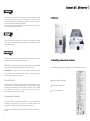
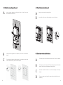
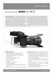
Growatt 3600MTL-US Growatt 4200MTL-US Growatt 5000MTL-US Installation GROWATT NEW ENERGY TECHNOLOGY Co.,LTD No.12 Building, Xicheng Industrial Zone, Bao’an District, Shenzhen, P. R.China T F E W + 86 755 2747 1900 + 86 755 2749 1460 [email protected] www.ginverter.com GR - UM - 005 - 02 & Operation Manual Directory 1 Notes on this manual 1.1 Validity 1.2 Target Group 1.3 Safety 2 Growatt MTL-US Inverter 3 Unpacking and inspection 4 Installation 5 Electrical Connection 5.1 System Diagram with Inverter Electrical connection 5.2 Safety 5.3 Connecting to the grid (AC utility) 5.4 Connect to PV Panel (DC input) 5.5 Commissioning Checking 6 Display and Messages 6.1 LCD display 6.2 LCD control 6.3 Setting the LCD display Notes on this manual 7 Modes of Operation 8 Inverter Status 9 Communications 1.1 Validity This manual describes the assembly, installation, commissioning and maintenance of the following Growatt Inverters: Growatt 3600 MTL-US Growatt 4200 MTL-US Growatt 5000 MTL-US 9.1 Communications software instructions 9.2 Monitor 10 Trouble Shooting 11 System Fault 12 Inverter Failure 13 Specifications 14 Growatt Factory warranty 15 Warranty Conditions 1 This manual does not cover any details concerning equipment connected to the Growatt MTL-US ( e.g. PV modules). Information concerning the connected equipment is available from the manufacturer of the equipment. 1.2 Target Group This manual is for qualified personnel. Qualified personnel have received training and have demonstrated skills and knowledge in the construction and operation of this device. Qualified personnel are trained to deal with the dangers and hazards involved in installing electric devices. Additional information Find further information on special topics in the download area at www.ginverter.com 1.3 Safety Appropriate Usage The Growatt is a PV Inverter that converts DC Current from PV generator into AC current. The Growatt is suitable for mounting indoors and outdoors. 16 Contact You can use the AC current gernerated as follows: 1 Growatt MTL-US Inverter House grid: Energy flows into the house grid. The consumers connected, for example, household devices or lighting, consume the energy. The energy left over is fed into the public grid. When the Growatt is not gernerating any energy, e.g., at night, the consumers which are connected are supplied by the public grid. The Growatt does not have its own energy meter. When energy is fed into the public grid, the energy meter spins backwards. 2.1 Overview Public grid Energy is fed directly into the public grid. The Growatt is connected to a separate energy meter. The energy produced is compensated at a rate depending on the electric power company. Stand-alone grid: The Growatt is connected to a stand-alone grid. The energy generated is consumed directly on site, surplus energy can be stored in batteries. 2.2 Identifying model and basic datasheet Info : Policies vary from one utility company to another. Consult with a representative of the local utility company before designing and installing a PV system. You can identify the pv inverter by the type label. It is on the left side of the enclosure. Information : Les règles peuvent varier d’une entreprise de service public à une autre. Veuillez consulter un représentant de l’entreprise de service public locale avant de concevoir et installer un système PV DC and AC Switch Separate the Growatt securely from the grid and the PV generators using DC and AC Switch. DC and AC Switch shall be able to disconnect all unground conductors after installation.You must provide an AC circuit breaker. If Growatt DC Switch is included in the delivery of the Growatt, it is used for operating the inverter but not disconnecting the inverter from the PV module. The type of product (Type/Model). Device-specific characteristics. Certificates and approvals. Grounding the PV modules The Growatt MTL-US is a transformerless inverter. That is why it has no galvanic separation. Do not ground the DC circuits of the PV modules connected to the Growatt MTL-US. Only ground the mounting frame of the PV modules. If you connect grounded PV modules to the Growatt MTL-US, the error message "PV ISO Low". 2 3 2 3 INSTALLATION Unpacking and inspection 4.1 Safety instructions After opening the package, please check the contents of the box. It should contain the following: A B E A D B C C D Item 4 Name 4 Quantity A solar inverter 1 B Mounting frame 1 C Safety-lock screws 4 D Mounting screws 8 E Mounting frame screws sleeve 8 F Monitor software(disk) 1(Optional) G manual 1 H Bluetooth 1(Optional) E F G All electrical installations shall be done in accordance with the local and national electrical codes ANSI/NFPA 70, NEC. The Growatt MTLUS inverters are listed to UL1741/IEEE1547 . Do not remove the casing. Inverter contains no user serviceable parts. Refer servicing to qualified service personnel. Both AC and DC voltage sources are terminated inside the PV Inverter. Please disconnect these circuits before servicing. When a photovoltaic panel is exposed to light, it generates a DC voltage. When connected to this equipment, a photovoltaic panel will charge the DC link capacitors. Energy stored in this equipment’s DC link capacitors presents a risk of electric shock. Even after the unit is disconnected from the grid and photovoltaic panels, high voltages may still exist inside the PVInverter. Do not remove the casing until at least 5 minutes after disconnecting all power sources. This unit is designed to feed power to the public power grid (utility) only. Do not connect this unit to an AC source or generator. Connecting Inverter to external devices could result in serious damage to your equipment. Carefully remove the unit from its packaging and inspect for external damage. If you find any imperfections, please contact your local dealer. Although designed to meet all safety requirements, some parts and surfaces of Inverter are still hot during operation. To reduce the risk of injury, do not touch the heat sink at the back of the PV-Inverter or nearby surfaces while Inverter is operating. 5 Consignes de sécurité A B C D E F G 6 Toute installation électrique doit être faite en accord avec les normes électriques locales et nationales ANSI/NFPA 70, NEC. Les onduleurs Growatt MTL-US sont listés à UL1741/IEEE1547. Ne pas retirer le revêtement. L’onduleur contient des parties non utilisables. Veuillez vous référer à un employé de service qualifié. Les sources de voltage CA et CC se trouvent à l’intérieur de l’onduleur PV. Veuillez déconnecter ces circuits avant manipulation. Lorsqu’un panneau photovoltaïque est exposé à la lumière, il génère un courant continu. Connecté à cet équipement, un panneau photovoltaïque rechargera les condensateurs de liaison CC. L’énergie stockée dans les condensateurs de liaison CC de cet équipement présentent un risqué de choc électrique. Même après la déconnection de l’unité de la grille et des panneaux photovoltaïques, une surtension peut toujours être présente dans l’onduleur PV. Ne pas retirer le revêtement jusqu’à au moins 5 minutes après avoir déconnectés toutes les sources d’énergie. 4.2 Selecting the INSTALLATION location A Raintight or wet location hubs that comply with the requirements in the Standard for Conduit, Tubing, and Cable Fittings, UL 514B, are to be used. B C The unit shall be mounted at least 914 mm (3 feet) above the ground. The installation method and mounting location must be suitable for the weight and dimensions of the inverter. Select a wall or solid vertical surface that can support the PV-Inverter. D E F G Mount on a solid surface,The mounting location must be accessible at all times. Vertical installation or tilted backwards by max. 15°. The connection area must point downwards. Do not install horizontally Cette unité a été conçue pour fournir de l’énergie uniquement aux réseaux électriques publics. Ne pas connecter cette unité à une source de courant alternatif ou à un générateur. Connecter un onduleur à des appareils externes peut causer de graves dommages à votre matériel. Retirer prudemment l’unité de son emballage et inspectez la pour d’éventuels dommages extérieurs. Si vous trouvez quelconques imperfections, veuillez contacter votre revendeur local. Bien que conçu afin de remplir tous les critères de sécurité, certaines parties ou surfaces de l’onduleur sont chaudes pendant son fonctionnement. Afin de réduire le risques de blessures, ne pas toucher le dissipateur de chaleur à l’arrière de l’onduleur PV et toute surface avoisinante lors du fonctionnement de l’onduleur. 7 4.3 Fixed the mounting on the wall 4.4 Fixed the inverter on the wall A A B Inverter requires adequate cooling space. Allow at least 20cm space above and below the inverter. B Using the mounting frame as a template, drill 4 holes as illustrated in image C Fix the mounting frame as the figure shows. Do not make the screws to be flush to the wall.Instead, leave 2 to 4mm exposed. Insert safety-lock screws to the bottom leg to secure the inverter. 4.5 Check Inverter Installation Status A B C D 8 Hang the inverter on the mounting frame. Check the upper straps of PV-Inverter and ensure it fits on to the bracket. Check the secure mounting of the PV-Inverter by trying to raise it from the bottom.The PV-Inverter should remain firmly attached. Select the installation location so that the status display can be easily viewed. Choose a strong mounting wall to prevent vibrations while inverter is operating. 9 5 Electrical Connection WARNING : All electrical installations shall be done in accordance with the local and national electrical codes ANSI/NFPA 70, NEC. AVERTISSEMENT : Toute installation électrique doit être effectué en accord avec les norms électriques locales et nationales ANSI/NFPA 70, NEC. Position Description A PV modules B DC load circuit breaker C Growatt PV Inverter D AC load circuit breaker E Energy meter F Utility grid WARNING: Policies vary from one utility company to another. Consult with a representative of the local utility company before designing and installing a PV system. AVERTISSEMENT: Les règles peuvent varier d’une entreprise de service public à une autre. Veuillez consulter un représentant de l’entreprise de service public locale avant de concevoir et installer un système PV. 5.1 System Diagram with Inverter Electrical connection Wire Box A B C D E 10 This unit or system is provided with fixed trip limits and shall not be aggregated above 30 kW on a single Point of Common Connection. PV Panel: Provide DC power to inverter. Converts DC (Direct Current) power from PV panel(s) to AC (Alternating Current) power. Because Inverter is grid-connected it controls the current amplitude according to the PV Panel power supply. Inverter always tries to convert the maximum power from your PV panel(s). Connection system: This “interface” between Utility and PV-Inverter may consist of electrical breaker, fuse and connecting terminals. To comply with local safety standards and codes, the connection system should be designed and implemented by a qualified technician. Utility: Referred to as “grid” in this manual, is the way your electric power company provides power to your place. 5.2 Safety The Growatt MTL-US Inverter must be connected to the AC ground from the utility via the Ground Terminal (PE). 11 5.3 Connecting to the grid (AC utility) 5.3.2 Connection of the AC wiring 5.3.1 GRID standards Before wiring the GROWATT MTL-US inverter, the installer needs to determine the grid configuration that the inverter will be connected to. The Growatt MTL-US inverter is default set for utility interconnection with 240Vac Split Phase from factory. However,you can choose the Net MODEL through the LCD to set the GROWATT MTLUS inverter to be fitted the commonly used utility configuration types shown in the figure 5.3.1. Based on the local GRID standards, it is possible to select different connection types. The available configurations are shown in the following table: A B C IMPORTANT: If several GROWATT MTL-US are installed in a tree-phase AC GRID. it is recommended to distribute the inverters between the phases in order to reduce the power unbalances between the phases. Always refer to the local standards. IMPORTANT: si plusieurs GROWATT MTL-US sont installés sur un réseau électrique à courant alternatif à trois phases. Il est recommandé de distribuer les onduleurs entre les phases pour réduire les déséquilibres de puissance entre les phases. Toujours vous référer aux normes locales. 12 D E Make sure grid (utility) configuration types ,if it is not the 240Vac Split Phase .you should use the LCD to set the right net model as chapter 6.3. Open the breaker or fuse between PV Inverter and utility. Open the wire box cover and the knockout. For Inverter , connect AC wires of all net model as figure 5.3.1: Cable requirements _(mm) Area(mm²) AWG no. Growatt 3600MTL-US _2.59 5.260 10 Growatt 4200MTL-US _2.59 5.260 10 Growatt 5000MTL-US _2.59 5.260 10 Product Model 13 5.4 Connect to PV Panel (DC input) D WARNING: ELECTRIC SHOCK HAZARD,THE DC CONDUCTORS OF THIS PHOTOVOLTAIC SYSTEM ARE NORMALLY UNGROUNDED BUT WILL BECOME INTERMITTENTLY GROUNDED WITHOUT INDICATION WHEN THE INVERTER MEASURES THE PV ARRAY ISOLATION! US,10Adc for 3600MTL-US. E High voltages exist when the PV panel is exposed to the sun. To reduce risk of electric shock, avoid touching live components and treat connection terminals carefully Cable requirements: Model There are two MPP trackers for GROWATT 3600MTL-US/ GROWATT 4200MTL-US/ GROWATT 5000MTL-US, so you can connect two independent MPP channels. (+) terminals and negative (-) terminals on the PV-Inverter. Each DC terminal on Inverter can withstand 15Adc for 5000MTL-US and 4200MTL- WARNING: RISK OF ELECTRIC SHOCK AND FIRE, USE ONLY WITH PV MODULES WITH A MAXIMUM SYSTEM VOLTAGE OF 600VDC ! Connect the positive and negative terminals from the PV panel to positive _(mm) Area(mm²) AWG no. Growatt 3600MTL-US _2.59 5.260 10 Growatt 4200MTL-US _2.59 5.260 10 Growatt 5000MTL-US _2.59 5.260 10 5.5 Commissioning Checking A B C Under any condition! Make sure the maximum open circuit voltage (Voc) Before connecting PV panels to DC terminals, please make sure the polarity is correct.Incorrect polarity connection could permanently damage the unit. Check short-circuit current of the PV string. The total maximum DC current. than 100 VDC but the AC grid is not yet connected, the message on the Inverter”-> “Waiting” -> “No AC connection”. The display repeats “No AC connection” and the LED will be red. Open the independent DC circuit breaker as well as the DC switch on the GROWATT MTL-US inverter. When the PV panels are connected and their output voltage is greater LCD display produce the following messages in order: “Growatt of each PV string is less than 600VDC. short-circuit current of the PV string should be less than the inverter’s 14 A B C D Close the AC breaker or fuse between PV-Inverter and grid. The normal operating sequence begins. Under normal operating conditions the LCD displays “Power: xxxx.xW”. That is the power fed to the grid. The LED turns green. This completes the check. 15 6 DISPLAY While Growatt inverter is working, the first line will normally show Power status: 6.1 LCD display Starting-up display sequence , once the PV power is sufficient , inverter displays information as shown in the flow chart as follow: Module: xxxxxx The Second line can change by knock on SerNo: xxxxxxxxxx FW Version: x.x.x The Second Line Of LCD Connect in: xxS Connect : OK Power: xxxx.xW CYCLE DISPLAY DISPLAY TIME/S REMARK 2 The inverter model 2 The software version 2 The Serial Number 4 The energy today 4 The energy all 4 PV input watt 6.2 LCD control To save power, the LCD display’s backlight automatically turns off after 30 seconds. The display on the inverter can be control by Knock on the front of it. The first line will show some status of the inverter, there are 5 status listed in below table. The First Line Of LCD STATE Wait State Inverter State DISPLAY CONTENT Standby PV voltage low Waiting Initial waiting Connect in xxS System checking Reconnect in xxS System checking Connect OK Connect to Grid Power: xxxx.xW 16 REMARK xxx Inverter watt at working Fault State Error: Auto Test State Auto Testing Protection auto test Program State Programming Update Software System Fault 17 CYCLE DISPLAY DISPLAY TIME/S 4 REMARK The PV and Bus Votage 6.3 Setting the LCD display Sound control can define the display language, luminance of the display, auto-test and utility model choice. When the LCD is dark, Knock and double knock make it becomes bright. Knock to make it display next information or change the set situation. Double knock make the display stand for 30 second on 1-5. And enter set menu. Setting language 4 The grid system Knock to make the display bright→ knock to“set language”→ double knock to enter“language: English”→ knock to select the language you need and wait until the display become dark. Setting luminance of the display Enable auto test 4 The enable auto test Knock to make the display bright → knock to“set LCD contrast”→ double knock to enter“LCD contrast 2”→ knock to select the luminance you need and wait until the display become dark. Setting communication address Set Language 4 Set Language Knock to make the display bright→ knock to “COM Address:xx” → double knock to change the Address model→clock to set address. setting utility model choice Set contrast 4 Set LCD Contrast 4 Set Communications Address 4 Set Grid Model Knock to make the display bright→ knock to“Net Model: xx” → double knock to enter“Net Model: xx”→ knock to select the grid model you need and wait until the display become dark. Set COM Address Set Grid Model 18 Auto test Knock to make the display bright→ knock to“Enable Auto test”→ double knock to enter “Waiting to start”→knock to start auto test and wait for the test result. 19 7 INVERTER STATUS 8 MODES OF OPERATION There are 3 different modes of operation. 7.1 Normal mode In this mode, Inverter works normally. Whenever the supplied power from PV panel is sufficient (voltage>150VDC), Inverter converts power to the grid as generated by the PV panel. If the power is insufficient(voltage<120VDC) ,Inverter enters a “waiting” state. Whilst “waiting” Inverter uses just enough power from the PV panel monitor internal system status. In normal mode the LED is green. 7.2 Fault mode The internal intelligent controller can continuously monitor and adjust the system status. If Inverter finds any unexpected conditions such as grid problems or internal failure, it will display the information on its LCD and the LED will be red. 7.3 Shutdown mode During periods of little or no sunlight, Inverter automatically stops running. In this mode, Inverter does not take any power from the grid. The display and LED’s on the front panel do not work. Inverter is designed to be user-friendly; therefore, the status of the Inverter can be easily understood by reading the information shown on the front panel display. All possible messages are shown in the following table. system fault DISPLAY OPERATION Auto Test Failed Auto Test do not pass No AC Connection No Utility, No Grid Connect PV Isolation Low Insulation Problem Output High DCI Output Current DC Offset too high PV Voltage High PV panel Voltage too high AC V Outrange Grid Voltage out of range AC F Outrange Grid Frequency out of range Inverter fault Notes: Operating inverter is quite easy. During normal operation, Inverter runs automatically. However, to achieve maximum conversion efficiency of Inverter,please read the following information: DISPLAY OPERATION Error: 100 2.5V Reference Voltage Fault Error: 101 Communication Fault Error: 102 Consistent Fault Error: 116 EEPROM Fault Automatic ON-OFF: Inverter starts up automatically when DC-power from the PV panel is sufficient. Error: 117 Relay Fault Once the PV-Inverter starts it enters one of the following 3 states: Error: 118 Init Model Fault 1. Error: 119 GFCI Fault Error: 120 HCT Fault Error: 121 Communication Fault Error: 122 Bus Voltage Fault Error: 123 Auto Test Fail Notes: Le fonctionnement d’un onduleur est assez facile. Lors d’une phase normale, l’onduleur fonctionne automatiquement. Cependant, afin d’atteindre l’efficacité de conversion maximale de l’onduleur, veuillez lire les instructions suivantes : 2. 3. 20 Standby: The PV string can only provide just enough voltage to minimum requirements of the controller. Waiting: When the PV string DC voltage is greater than 100V, Inverter enters “waiting” state and attempts to connect to the grid. Normal operation: When PV string DC voltage is greater than 150V, Inverter operates in the normal state. 21 9 COMMUNICATIONS 9.1 Communications software instructions Shine NET is a PC software that communicate with Shine Inverter to analyze the inverter working state. It is convenient for you to know the inverter real time working state and the history work information. TROUBLE SHOOTING 10 In most situations, the Inverter requires very little service. However, if Inverter is not able to work perfectly, please refer to the following instructions before calling your local dealer. Should any problems arise, the LED on the front panel will be red and the LCD displays the relevant information. Please refer to the following table for a list of potential problems and their solutions. Spec: A B C D E F G Communicate with inverter by RS232 and Bluetooth. Construct net with inverter , GRO monitor and Shine NET by RS232, Bluetooth and Internet. SYSTEM FAULT 11 Two Interfaces: Multi Inverter Interface and Wave Data Interface. In Multi Inverter Interface: See at most 4 inverters working data at the same time, you can select your own compare inverters and parameters. In Wave Data Interface: Query the inverter real time and history power wave , work data and error information. Multi languages: English, French, German, Spanish and etc. Ground Fault 1. The ground current is too high. 2. Unplug the inputs from the PV generator and check the peripheral AC system. 3. After the cause is cleared, re-plug the PV panel and check PV-Inverter status. Support OS: Win XP / Vista/win 7/2000/2003. 9.2 Monitor After setting the software the user can monitoring the inverter. The right side of the main interface is the detailed information of inverter. 4. If the problem persists please call service. Isolation Fault 1. Check the impedance is between PV (+) & PV (-) and the PV-Inverter is earthed. The impedance must be greater than 8M. 9.3 Detailed information 2. If the problem persists please call service. Detailed setting method and other functions refer to “Shine NET Manual.” in the CD. 22 23 SPECIFICATIONS 13 No Utility 1. Grid is not connected. 2. Check grid connection cables. 3. Check grid usability. 12 INVERTER FAILURE PV Over Voltage 3600MTL - US 4200MTL - US 5000MTL - US Max. DC power 3800W 4400W 5200W Max. DC voltage 600V 600V 600V Start voltage 100V 100V 100V DC nominal voltage 360V 360V 360V PV voltage range 70V - 600V 70V - 600V 70V - 600V MPP voltage range 120V - 550V 120V - 550V 120V - 550V Number of independent MPP trackers/strings per MPP tracker 2/2 1/2 1/2 12A / 12A 14A / 14A 15A / 15A Input Data Max. input current of the MPP tracker Output Data 1. Check the open PV voltage, see if it is greater than or too close to 600VDC. Nominal AC output power 3600W 4200W 4600W 2. If PV voltage is less than 600VDC, and the problem still occurs, please call Max. output current 18A / 17.1A / 14.8A 21A / 20A / 17.2A 22A / 23.7A / 20.5A local service. Consistent Fault 1. Disconnect PV (+) or PV (-) from the input, restart the PV-Inverter. 2. If it does not work, call service. > If there is no display on the panel, please check PV-input connections. If the voltage is higher than 150V, call your local service. > During periods of little or no sunlight, the PV-Inverter may continuously AC nominal voltage; range Default:240V single phase optional:208,240or277 single phase 183-228@208V 211-264V@240V 244-305@277V AC grid frequency; range 60Hz; 59.3-60.5Hz 60Hz; 59.3-60.5Hz 60Hz; 59.3-60.5Hz Phase shift (cosφ) 1 1 1 THDI <3% <3% <3% AC connection Single phase Single phase Single phase Max . efficiency 98% 98% 98% CEC.effciency 97% 97% 97% MPPT efficiency 99.5% 99.5% 99.5% Efficiency start up and shut down. This is due to insufficient power generated to operate the control circuits. 24 25 3600MTL 4200MTL 3600MTL 4200MTL 5000MTL DC connection: Terminals yes yes yes AC connection: Terminals yes yes yes LCD displqy yes yes yes 5000MTL Features Protection Devices DC reverse polarity protection yes yes yes PV Ground fault protection yes yes yes Insulation Resistance low protection yes yes yes AC short-circuitprotection yes yes yes Grid monitoring yes yes yes Interfaces: RS485/RS232/ Bluetooth/RF/ZigBee yes / yes / opt / opt / opt yes / yes / opt / opt / opt yes / yes / opt / opt / opt Anti islanding protection yes yes yes Warranty:10years/15years yes / opt yes / opt yes / opt Dimensions (W / D / H) in mm 360/650/188 360/650/188 360/650/188 Weight 28.3 KG 28.3 KG 28.3 KG General Data Certificates and approvals Ul1741, IEEE1547, CSA C22.2 No.107.1,FCC Part15(Class A&B) Altitude Up to 2000m without power derating Efficiency Curve Operating temperature range –25°C..+60°C –25°C..+60°C –25°C..+60°C Continuous full output power temperature range –25°C..+45°C –25°C..+45°C –25°C..+45°C Noise emission (typical) ≤ 25 dB(A) ≤ 25 dB(A) ≤ 25 dB(A) Consumption: operating (standby) / night <5W /< 0.5 W <5W /< 0.5 W <5W /< 0.5 W Topology transformerless transformerless transformerless ENCLOSURE Type 3R Type 3R Type 3R Cooling concept Natural cool Natural cool Natural cool Installation: Indoor /Outdoor 26 yes / yes yes / yes yes / yes 27 14 Growatt Factory warranty The “Limited Product Warranties” described above shall not apply to, and Growatt shall have no obligation of and kind whatsoever with respect to, any This certificate represents a 10 year warranty for the Growatt inverter products listed below. Possession of this certificate validates a standard factory warranty of 10 years from the date of purchase. Warranted products This warranty is applicable solely to the following products: Growatt 3600MTL-US, Growatt 4200MTL-US, Growatt 5000MTL-US. inverter which has been subjected to: — — — — — — — — — Misuse, abuse, neglect or accident; Alteration, improper installation or application; Unauthorised modification or attempted repairs; Insufficient ventilation of the product; Transport damage; Breaking of the original manufacturers seal; Non-observance of Growatt installation and maintenance instruction; Failure to observe the applicable safety regulations Power failure surges, lighting, flood, fire, exposure to incorrect use, negligence, accident, force majeure, explosion, terrorist act, vandalism or damage caused by incorrect installation, modification or extreme weather conditions or other circumstances not reasonably attributable to Growatt. Limited Product Warranty The warranty shall also cease to apply if the product cannot be correctly identified as the product of Growatt. Warranty claims will not be honored if the type of serial number on the inverters have been altered, removed or rendered illegible. ( Applicable under normal application, installation, use and service conditions) Growatt warrants the above listed products to be free from defects and/or failure specified for a period not exceeding ten (10) years from the date of sale as shown in the Proof of Purchase to the Original purchaser. Liability The liability of Growatt in respect of any defects in its PV inverters shall be limited to The warranties described in these “Limited Warranties ” are exclusive and are expressly in lieu of and exclude all other warranties, whether written, oral, express or implied, including but not limited to, warranties of merchantability and of fitness for a particular purpose, use ,or application, and all other obligations or liabilities on the part of GROWATT , unless such other obligations or liabilities are expressly agreed to it in writing signed and approved by GROWATT , GROWATT shall have no responsibility or liability whatsoever for damage or injury to persons or property, or for other loss or injury resulting from any cause whatsoever arising out of or related to the modules, including, without limitation, any defects in the modules or from use or installation. Under no circumstances shall GROWATT be liable for incidental, consequential or special damages howsoever caused; loss of use, loss of production, loss of revenues are therefore specifically and without limitation excluded to the extent legally permissible, GROWATT ’s aggregate liability, if any, in damages or otherwise, shall not exceed the invoice as paid by the customer. 28 compliance with the obligations as stated in these terms and conditions of warranty. Maximum liability shall be limited to the sale price of the product. Growatt shall accept no liability for loss of profit, resultant of indirect damage, any loss of electrical power and / or compensation of energy suppliers within the express meaning of that term. The warranty rights as meant herein are not transferable or assignable to any third party excepting the named warranty holder. 29 15 Warranty conditions If a device becomes defective during the agreed Growatt factory warranty period and provided that it will not be impossible or unreasonable, the device will be, as selected by Growatt, 1. Shipped to a Growatt service center for repair, or 2. repaired on-site, or 3. exchanged for a replacement device of equivalent value according to model and age. The warranty shall not cover transportation costs in connection with the return of defective modules. The cost of the installation or reinstallation of the modules shall also be expressly excluded as are all other related logistical and process costs incurred by all parties in relation to this warranty claim. 16 Contact If you have technical problems concerning our products, contact your installer or Growatt. During inquiring, please provide below information: 1. Inverter type 2. Modules information 3. Communication method 4. Serial number of Inverters 5. Error code of Inverters 6. Display of inverters 30