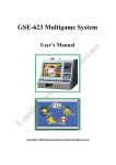
Download GSE-623 Amusement game (Fun World)
Transcript
GSE-623 Amusement game (Fun World)
Manual
I. Amusement Game setting
Press Test on the main screen to enter testing function as follows:
Fun World Setup Operation
No.
Name
Description
1
TOUCH
Touch screen adjustment(640 x 480 resolution adjustment)
2
SOUND
Sound adjustment
3
COIN
Counter adjustment
4
GAME SETUP
Game setting
5
COUNTER
Record checking
6
HIGH SCORES
Record of the highest score
7
STATISTICS
Game playing times
8
DEMO INFO
9
ADVANCED
Demo information
Advance setting about Time, demo and game
10
EXIT
Exit the game
II. Hardware installation, wiring
1. Kits
(1) Installation CD × 3
(2) Funny622 PCB × 1
(3) USB KEY × 1
(4) KEY PRO × 1
(5) Wiring Diagram × 1
(6) User's Manual × 1
(7) wires × 1
2. System Requirement
(1) Motherboard: GIGABYTE Motherboard(VIA Chip Set)
1
(2) CPU: Intel Pentium III 800MHZ or above
(3) Hard Disk: 10GB or above
(4) Sound Card: Cmedia 8738 series Sound Card
(5) VGA Card: Geforce II MX-200/400 or above
(6) Don’t use Sis, S3 or VIA Display card motherboard.
If you must use All-in-One
motherboard, please use Intel (present default is 855GME) display module and
Cmedia8738 Sound card motherboard.
(7) BIOS: Take Award BIOS as example
3. Installation
(1) Prepare a computer with CD-ROM player and a 10GB Hard Disk. Please also
connect the mouse and keyboard with the computer.
(2) Power On the computer then keeps pressing Delete to enter BIOS for system
set-up
(3) Choose "BIOS ADVANCED SETUP" Î Modify "FIRST BOOT DEVICE"
into CD-ROM Î Save Î Exit (It means Power On by CD-ROM.)
(4) Power On the computer Î Put in CD1 Î GHOST Î CD2 Î GHOST Î CD3
Î GHOST Î Finish Î Restart and takes off CD3 Î Find New Hardware
(5) Install Driver Î OK Î the system will execute automatically and the message of
“KEYPRO error” will be shown.
(6) Arrange wiring according to Funny622 IC wiring diagram.
(7) Plug KEYPRO into PRINT PORT of motherboard.
(8) Plug the USB on USB slot of motherboard.
(9) Remove plug of Keyboard and plug the wire DB9 of Funny622 to replace it.
(10) "Y" and "H" on the computer keyboard are used as "Coin In" and "KEYIN" of
the game so you have to "Disconnect" the keys before you run the business.
(11) Power On.
If the system can read KEYPRO and USB KEY correctly, the game
menu will appear and player can start to coin in and play the game.
2
III. Funny622 Wiring (GSE623 I/O Interface Card)
JP 1:Power In
JP 2:Power In
1 DC+24V
2 GND
1
2
3
4
JP 3:to PS2
1
2
3
4
DC+12V
GND
GND
DC+5V
DC+5V
GND
DATA(To PS2 Female)
CLK(To PS2 Female)
JP4:From Keypro(Connected to Printer Port)
JP5:Input/Output
1
2
3
4
5
6
7
8
9
10
11
12
1
2
3
4
5
6
7
8
9
10
11
12
13
14
15
16
BET Lamp
Start Lamp
Hold 1 Lamp
Hold 2 Lamp
Hold 3 Lamp
Hold 4 Lamp
Hold 5 Lamp
Game MENU Lamp
Hopper Switch→至 JP6 之 P5
Key in Counter
Key out Counter
JP6:Only for Hopper
1 GND
2 GND
3 DC+24V(output)
4 DC+12V(output)
5 H.P. SW → 從 JP4 之 P10
6 SSR
* You must use electronic meter.
+12V
P2:D Type 25PIN(Male)
13
DC+24V(OUTPUT)
HOLD 5 SW
Reserved
GND
Reserved
P1:D Type 9PIN (Male)(The same as JP3)
GND(To PS2 Keyboard Female GND)
+5V → for Counter
GND → for Counter
Coin in SW
Key in SW
BET Lamp
Start Lamp
Hold 1 LampHold 2 Lamp
Hold 3 Lamp
Hold 4 Lamp
Hold 5 Lamp
Game MENU Lamp
+12V
5
9
10
9
PAYOUT SW
BET SW
ESCAPE SW
COIN IN SW
KEYOUT SW
KEYIN SW
SETUP SW
START SW
6
25
2
4
23
22
21
8
20
7
19
8
3
7
+5V( To PS2 Keyboard Female+5V)
11
GAME MENU SW
HOLD 2 SW
SSR
HOLD 3 SW
HOLD 4 SW
DATA(To PS2 Keyboard Female DATA) 4
CLK(To PS2 Keyboard Female CLK)
12
2
6
5
4
3
15
2
1
GND
HOLD 1 SW
3
18
1
7
16
1
14
IV. Wiring of Printer(KEYPRO)
◎Diagram(Female)
1
COUNTERS ACTIVATION
2
BET LAMP
3
START LAMP
1
4
HOLD 1 LAMP
2
5
HOLD 2 LAMP
3
6
HOLD 3 LAMP
4
7
HOLD 4 LAMP
5
8
HOLD 5 LAMP
6
9
GAME MENU LAMP
7
10
N/C
8
11
N/C
9
12
HOPPER SWITCH
10
13
N/C
11
14
CASH IN COUNTER
12
15
N/C
13
16
N/C
17
CASH OUT COUNTER
18
N/C
19
N/C
20
N/C
21
N/C
22
N/C
23
N/C
24
N/C
25
N/C
14
15
16
17
18
19
20
21
22
4
23
24
25


