1
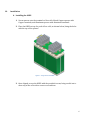
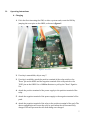
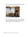
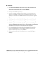
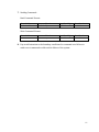
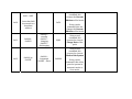
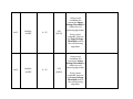
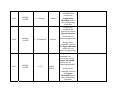
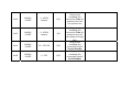
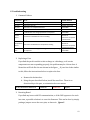
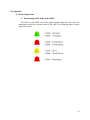
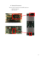
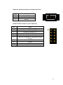
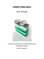
LPRDS-CMS-2011
User Manual
Lafayette Photovoltaic Research and Development System
Cell Management System
ECE492 – Spring 2011
Table of Contents
I. Introduction
II. Getting Started
A. System Components
B. Extras
C. Warnings
III. Installation
IV. Operating Instructions
A. Charging
B. Discharging
C. I2C Operation
V. I2C Instruction Set
VI. Troubleshooting
A. System Reset
B. Replacing a Fuse
VII. Appendix
A. Board Components
B. Cell Maintenance
2
I.
Introduction
Cell Management System (CMS)
The main function of the CMS is to balance and monitor the state of charge of
a pack of four Lithium Iron Phosphate Cells. The CMS can be used in automatic
mode, and can also be easily monitored and controlled via I2C communication. Each
pack of cells contains a single Printed Circuit Board (PCB), which is referred to as
the OBPP (One Board Per Pack). The OBPP acts as the brain of the CMS, as well as a
visual indicator of the state of the CMS.
Under automatic conditions, a pack of 4 cells can be charged or discharged by
the user and the CMS will automatically balance the cells’ state of charge over
several cycles, thus improving the lifetime of the cells, and improving the pack
performance. The user can visually monitor charge and discharge cycles by
observing the LED indicators on the OBPP. For more information about these
indicators, see Operating Instructions Section.
In addition to automatic mode, the user can also control and monitor the CMS
from a PC terminal. A range of commands allows the user to set cell bypass
conditions, change parameters, or read cell voltages, current, or temperature. For
more about this command set, see the Operating Instructions Section.
3
II.
Getting Started
A. System Components
1. Batteries - The Cell Management System includes 4 Li-Ion batteries. Specifically,
the batteries are Lithium Iron Phosphate (LiFePO4) cells.
Capacity: 3.2V, C = 10Ah
Size: 82x27x108 mm (L x W x H).
2. One Board Per Pack (OBPP) - The OBPP is the board responsible for managing
and monitoring each cell in a pack of four cells. This board must be mounted in the
appropriate orientation onto a pack of four cells. See the Installation Section for
instructions.
3. Screws and Spacers- Provided with the CMS are:
Spacers: Four (4) Aluminum, four (4) copper
Screws: 8 (5/8” 10-32)
Lock Washers: 8 (10-32)
4. Cables-Provided with the CMS are:
Power Cable: 1 to connect to another pack in series
I2C Cable: 1 for connection to I2C bus
5. PC to I2C Converter: The converter provided with the CMS is necessary for the
use of the I2C features. This device is used to convert either RS-232 or USB to I2C.
6. RealTerm: This is free software that is useful for sending basic hex/ascii/binary
commands via a PCs USB or RS-232 COM ports. This software is used for sending
basic I2C commands.
4
B. Extras You May Need
1. Constant Current Power Supply- For cell charging, it is recommended to use a
constant current source. The current source should be limited to no more than 2C
(20A). It is recommended to use a constant 10A source, which will charge an empty
pack in about 1 hour.
3. Relay- It may be convenient to use a relay when charging a pack. A common
emitter output on the OBPP provides a logic high output when a pack becomes fully
charged, and a logic low when the pack is fully discharged. Connecting a power
supply or load to the pack through a relay controlled by this output will prevent the
pack from being over charged or over discharged. In the event that a relay is not
available, the user can view and LED indicator on the OBPP that will signify when
charging or discharging is complete.
4. Safety Glasses- Please be cautious when working with high voltage electronics.
Particularly when connecting several packs in series, or installing the OBPP, it is
important to wear safety glasses.
5. PicKit Serial Programmer: The PicKit is a device that is used for In Circuit Serial
Programming (ICSP) of PIC u-controllers. This device may be needed if the CMS
firmware requires recompiling or software updates.
C. Warnings
1. DO NOT short the terminals of any cells. This could result in serious injury or
cause the permanent damage to the CMS and/or cells.
2. DO NOT touch heat sinks while board is in operation. They, or other components
on the board may become extremely hot!
5
III.
Installation
A. Installing the OBPP
1. Screw spacers onto the terminals of four cells. Match Copper spacers with
Copper terminals, and Aluminum spacers with Aluminum terminals
2. Place the OBPP on top of a pack of four cells, as shown below, lining the holes
with the top of the spacers.
Figure 1- Single Pack with OBPP
3. Once aligned, secure the OBPP with the provided screws, being careful not to
short any of the cells with a screw or screwdriver.
6
IV.
Operating Instructions
A. Charging
1. If it is the first time using the CMS, or after a system crash, reset the CMS by
jumping the reset pins on the OBPP, as shown in figure 2.
Figure 2 – Reset Pin
2. If a relay is unavailable, skip to step 7.
3. If a relay is available, attach the positive terminal of the relay switch to the
“Done” pin on the OBPP and the negative terminal of the relay switch to the
“GND” pin on the OBPP. Use a 10KOhm Resistor to pull up the “Done” Signal to
VDD.
4. Attach the positive terminal of the power supply to the positive terminal of the
relay.
5. Attach the negative terminal of the power supply to the negative terminal of the
pack.
6. Attach the negative terminal of the relay to the positive terminal of the pack. The
above configuration will cause the relay to open when the cell becomes fully
charged. This will prevent the cells from being over charged.
7
7. For a setup without a relay, connect the positive terminal of the power supply to
the positive terminal of the pack, and the negative terminal of the power supply
to the negative terminal of the pack as show in figure 3.
Figure 3- Power/ Load Connector
8. After checking to make sure the relay is closed (on), turn on the power supply so
that it is current limited within a range of 5-20A. Once on, the pack will begin to
charge. The green LED labeled “CHRG” should blink, as well as the yellow LED
labeled “ON.” If this is not the case, perform a system reset, or refer to the
maintenance manual for instructions to reprogram the CMS.
*Note: DO NOT turn a power supply on before attaching to a pack.
8
B. Discharging
1. If it is the first time using the CMS, or after a system crash, reset the CMS by
jumping the reset pins on the OBPP, as shown in figure 2.
2. If a relay is unavailable, skip to step 7.
3. If a relay is available, attach the positive terminal of the relay switch to the
“Done” pin on the OBPP and the negative terminal of the relay switch to the
“GND” pin on the OBPP. Use a 10KOhm Resistor to pull up the “Done” Signal to
VDD.
4. Attach the positive terminal of the load* to the positive terminal of the pack.
5. Attach the negative terminal of the load to the positive terminal of the relay.
6. Attach the negative terminal of the relay to the negative terminal of the pack.
The above configuration will cause the relay to open when the cell becomes fully
discharged. This will prevent the cells from being over discharged.
7. For a setup without a relay, connect the positive terminal of the load to the
positive terminal of the pack, and the negative terminal of the load to the
negative terminal of the pack as show in figure 3.
8. Check to make sure the relay is closed (on), once on, the pack will begin to
discharge.
* DO NOT use a load that requires more than 20A. Doing so could cause the fuse to give
out, or in certain situations cause permanent damage to the CMS.
9
C. I2C Operation
1. If it is the first time using the CMS, or after a system crash, reset the CMS by
jumping the reset pins on the OBPP, as shown below.
2. Open RealTerm I2C. If RealTerm I2C is not installed on your PC, go to:
http://realterm.sourceforge.net/index.html#downloads_Download
To download, as well as for RealTerm help.
3. Using either an RS-232 or USB cable, connect the PC to I2C converter to the PC
running RealTerm I2C.
4. Connect the provided I2C communication cable between the PC to I2C converter
and the OBPP. Be sure to orient the cables as shown below.
5. In RealTerm, under the ‘Port’ tab:
a. Select ‘Baud’ of 57600
b. Select ‘Port’ 3, the Port number for the USB port
c. Set ‘Parity’ to ‘None’
d. Set ‘Data Bits’ to ‘8’
e. Set ‘Stop Bits’ to ‘1 bit’
f. Set ‘Hardware Flow Control’ to ‘RTS/CTS’
g. Set ‘Software Flow Control’ to ‘Xon Char: 17’ and ‘Xoff Char: 19’. Do not
check ‘Receive’ or ‘Transmit’
h. Click ‘Change’ Button to save settings
6. In RealTerm, under the ‘I2C’ tab:
a. Set ‘Bus Num’ to ‘1’
b. Set ‘Address’ to 0x54, which is the default address of an OBPP, or else set
to the known address of the board.
c. Set ‘SubAddr=’ to 0
10
7. Sending Commands
Read Command Format:
Board Address
Default 0x54
Command Number
(0x00-0x1B)
Data Byte High
0xF0
Data Byte Low
0x00
Board Address
Default 0x54
Command Number
(0x00-0x1B)
Data Byte High
0x0X
Data Byte Low
0xXX
Write Command Format:
8. Pay careful attention to the boundary conditions for command sets. Failure to
send correct commands could result in failure of the system.
11
D. I2C Instruction Set Comma
Input Range nd # 0x00 0x01 0x02 0x03 0x04 0x0000 ‐ 0x0FFF 0x0000 ‐ 0x0FFF 0x0000 ‐ 0x0FFF 0x0000 ‐ 0x0FFF 0x0000 ‐ 0x0FFF Value Range ‐25A ‐ 25 A 0 ‐ 5 V 0 – 5 V 0 – 5 V 0 – 5 V Default Value Description Calculation R/O Using a read command, this returns the current passing through the addressed board. Calculate current from returned hex value (X) as: R/O R/O R/O R/O Using a read command, this returns Cell 1 Voltage. Using a read command, this returns Cell 2 Voltage. Calculate voltage from returned hex value (X) as: Calculate voltage from returned hex value (X) as: Using a read command, this returns Cell 3 Voltage. Calculate voltage from returned hex value (X) as: Using a read command, this returns Cell 4 Voltage. Calculate voltage from returned hex value (X) as: 0x05 0x06 0x07 0x08 0x09 0x0000 ‐ 0x0FFF 0x0000 ‐ 0x0FFF 0x0000 ‐ 0x0FFF 0x0000 ‐ 0x0FFF 0x01F4 – 0x34BC ~1% ‐ ~99% R/O R/O R/O R/O R/O Using a read command, this returns Cell 1 Temperature. Using a read command, this returns Cell 2 Temperature. Using a read command, this returns Cell 3 Temperature. Using a read command, this returns Cell 4 Temperature. Using a read command, this returns the State of Charge of the pack of cells addressed. Calculate temperature (°C) from returned hex value (X) as: .
.
Calculate temperature (°C) from returned hex value (X) as: .
.
Calculate temperature (°C) from returned hex value (X) as: .
.
Calculate temperature (°C) from returned hex value (X) as: .
.
Calculate the State of Charge (%) from the returned hex value (X) as: 0x0A 0x0B 0x0C 0x0000 – 0xFFFF 0x0000 – 0x0FFF b1‐b11 = duration b0 = 0n(1) or Off(0) 0x0000 – 0x0FFF b1‐b11 = duration b0 = 0n(1) or Off(0) 0 – 65,536 min 0 – 2,048 min On or Off 0 – 2,048 min On or Off R/O Using a read command, this returns Total Run Time since last reset. Calculate run time from returned hex value (X) as: T = (X to Decimal) 0x0000 0 min / Off Using a read command, this returns the State of Bypass 1 Using a write command, this can turn Bypass 1 On for the specified amount of time, or Off If Bypass 1 is on, Rightmost bit returned is 1, otherwise, it is 0 0x0000 0 min / Off Using a read command, this returns the State of Bypass 2 Using a write command, this can turn Bypass 2 On for the specified amount of time, or Off If Bypass 2 is on, Rightmost bit returned is 1, otherwise, it is 0 0x0D 0x0000 – 0x0FFF b1‐b11 = duration b0 = 0n(1) or Off(0) 0 – 2,048 min On or Off 0x0000 0 min / Off 0x0E 0x0000 – 0x0FFF b1‐b11 = duration b0 = 0n(1) or Off(0) 0 – 2,048 min On or Off 0x0000 0 min / Off 0x0F 0x0000 or 0x00FF Off (0x0000) or On(0x00FF) Off (0x0000) Using a read command, this returns the State of Bypass 3 Using a write command, this can turn Bypass 3 On for the specified amount of time, or Off Using a read command, this returns the State of Bypass 4 Using a write command, this can turn Bypass 4 On for the specified amount of time, or Off Using a read command, this returns the current State of the Done Signal Using a write command, this can set the Done Signal either high or low If Bypass 3 is on, Rightmost bit returned is 1, otherwise, it is 0 If Bypass 4 is on, Rightmost bit returned is 1, otherwise, it is 0 0x10 0x11 0x12 0x01 – 0xFF *note that 0x00 is reserved as a broadcast address 0x0000 – 0x0002 0x0000 – standby 0x0001 – charging 0x0002 – discharging 0x0000 or 0x00FF 0x0000 – Automatic 0x00FF – Slave 0x54 Using a read command, this returns the Current Address of the board Using a write command, this can change the Current Address of the board R/O Using a read command, this returns the current Charge State of the pack. 0x0000 Using a read command, this returns the current Mode of the System Using a write command, this either puts the system in automatic mode or slave mode. 0x13 0x14 0x0000 – 0x0FFF 0x0000 – 0x0FFF 0 – 5V 0 – 5V 3.8V (0xC29) Using a read command, this returns the Upper Voltage Threshold of used in the cell balancing algorithm. Using a write command, this sets the Upper Voltage Threshold used in the cell balancing algorithm. 2.8V (0x8F6) Using a read command, this returns the Lower Voltage Threshold of used in the cell balancing algorithm. Using a write command, this sets the Lower Voltage Threshold used in the cell balancing algorithm. 0x15 0x16 0x17 0x0000 – 0x0FFF 0x0000 – 0x00FF 0x0000 – 0x0FFF 0 – 255 deg C 0 – 255 minutes 0 – 5 V 0xB0A Using a read command, this returns the Temperature Threshold used in the cell balancing algorithm 0x0014 Using a read command, this returns the current Bypass Duration used in the cell balancing algorithm. Using a write command, this sets the Bypass Duration used in the cell balancing algorithm. Using a read command, this returns the current Bypass Threshold used in the cell balancing algorithm. Using a write command, this sets the Bypass Threshold used in the cell balancing algorithm. 0x0029 (50mV) 0x18 0 – 65636 minutes R/O 0x19 0x0000 – 0xFFFF 0 – 65636 minutes R/0 0x1A 0x0000 – 0xFFFF 0.0 – 255.255 R/O 0x1B 0x0000 – 0xFFFF 0 – 255 R/O 0x0000 – 0xFFFF Using a read command, this returns the Time (in minutes) since the last system reset. Using a read command, this returns the Time (in minutes) since the last change in charge state. Using a read command, this returns the Board’s Version Number Using a read command, this returns the Board’s Serial Number E. Troubleshooting
1. Common Failures
Component
Error
Possible Solution
Batteries
Cell appears to have capacity of less than 10 A-h
Replace Cell
Any LED
LED never turns on
Replace Green LED
Any LED
LED acts in an unexpected manner
Reset OBPP
2
IC
2
Reset OBPP
2
Reset OBPP
See Maintenance
Manual for
Instructions to replace
Current Sensor
See Maintenance
Manual for
Instructions to replace
Temperature Sensor
Replace Fuse
Reset OBPP
I C Read Returns 0xFFFF or other unexpected value
2
IC
I C Write does not change parameters as expected
Current
Sensor
I C returns invalid data for Current reading
Temperature
Sensor
I2C returns invalid data for Temperature reading
Fuse
2
CMS unable to be charged/ discharged - I2C not responding
as expected
2. Replacing a Fuse
If you find the pack is unable to take a charge or a discharge, or if certain
components are not responding properly, the problem may be a blown fuse. A
blown fuse will look like the one shown in the figure __. If your fuse looks similar
to this, follow the instructions below to replace the fuse.
a. Remove the broken fuse.
b. Using the part described below, install the new Fuse. There is no
directionality to the part, so orientation does not matter.
25 Amp Automotive Blade Fuse
F1018-ND
Blade Fuse
Digikey
3. Resetting Board
If you find any issues with I2C communication, or if the CMS appears to be stuck
in a state, a possible solution is to reset the firmware. This can be done by simply
putting a jumper across the reset pins, as shown in figure 2.
12
VII. Appendix
A. Board Components
a. The meaning of the LED’s on the OBPP
The LED’s on the OBPP are visual signals which inform the users and the
maintainers about the current status of the CMS. The following figure depicts
what LED’s mean:
Figure 4 - OBPP LEDs
13
b. Pinouts of all connectors
There are two (2) connectors on the OBPP, which are:
- Anderson connector
- Data connector
Figure 5 - Anderson Connector
Figure 6 - I2C Data Connector
Figure 7 - OBPP 1
14
Pinout for Anderson Connector (3-pin connector)
Pin #
Signal
1
2
3
Power (+12V)
No Connection
Ground
1
2
3
Pinout for Data Connector (2x5 connector)
Signal
1
2
3
4
5
External Power (+5V)
External SDA (data for I2C)
External SCL (clock for I2C)
No Connection
No Connection
External RTSS (Redundant Temperature Sensing
System)
External Done
Ground
No Connection
No Connection
6
7
8
9
10
5
J3
Pin #
5
10
3
8
4
9
2
7
1
6
15