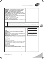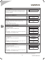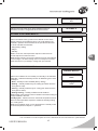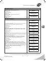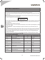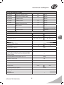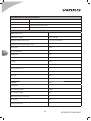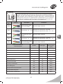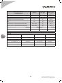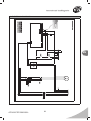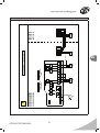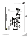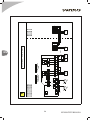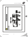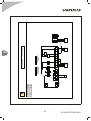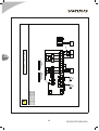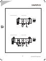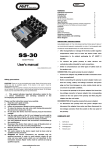
1
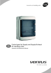
EN Compact control boxes NVS... CG OPTIMA SUP for supply duct air handling units Compact control boxes NVS... CG 0-2 for exhaust ventilating units Operation an Maintenance manual DTR - CG OPTIMA - ver.2.0 (05.2012) RU Control boxes NVS... CG OPTIMA SUP and NVS... CG 0-2 are designed according to the European standards: EN 60335-1; EN 60439-1; EN 60439-3; EN 50082-1; EN 50081-1 www.vtsgroup.com Table of content I. USER'S MANUAL ............................................................................................. 3 INTRODUCTION - NVS... CG OPTIMA SUP......................................................................................................................... 3 INTRODUCTION - NVS... CG 0-2 .......................................................................................................................................... 3 USER'S MANUAL NVS CG 0-2 ................................................................................................................................................. 4 1. DESCRIPTION OF CONTROLS ......................................................................................................................................... 4 MAINS SWITCH ...................................................................................................................................................................... 4 MOTOR SWITCH..................................................................................................................................................................... 4 CONTROL MODE SWITCH .................................................................................................................................................... 4 USER'S MANUAL NVS CG OPTIMA ........................................................................................................................................ 5 1. DESCRIPTION OF CONTROLS ............................................................................................................................................ 5 MAINS SWITCH ..................................................................................................................................................................... 5 MOTOR SWITCH ................................................................................................................................................................... 5 SIGNALLING CONTROLLER STATUS ................................................................................................................................. 6 CONTROL PANEL HMI OPTIMA........................................................................................................................................... 6 SYSTEM START-UP .............................................................................................................................................................. 7 SWITCHING ON POWER SUPPLY ....................................................................................................................................... 7 QUICK START ........................................................................................................................................................................ 7 2. APPLICATION BASICS .......................................................................................................................................................... 8 HMI SETTINGS & CONNECTING TO THE CONTROLLER ................................................................................................. 9 LANGUAGE SELECTION English / Polski / Русский ...........................................................................................................10 ENTERING THE PASSWORD ..............................................................................................................................................10 3. CALENDAR .......................................................................................................................................................................10 CALENDAR ANNUAL ..................................................................................................................................................11 CALENDAR MONTHLY ................................................................................................................................................11 CALENDAR WEEKLY ..................................................................................................................................................11 CALENDAR DAILY .......................................................................................................................................................12 CALENDAR EXAMPLE .........................................................................................................................................................12 4. PARAMETERS ..................................................................................................................................................................14 PARAMETERS DAMPERS ..........................................................................................................................................14 PARAMETERS FANS ..................................................................................................................................................14 PARAMETERS WATER HEATER ................................................................................................................................14 PARAMETERS COOLER .............................................................................................................................................14 PARAMETERS PREHEATER ......................................................................................................................................14 5. SETTINGS .........................................................................................................................................................................15 SETTINGS DEF. WORK MODE ...................................................................................................................................15 SETTINGS STANDBY MODE ......................................................................................................................................15 SETTINGS PERFORMANCE ......................................................................................................................................16 SETTINGS TEMP. REGULATOR .................................................................................................................................16 SETTINGS FANS .........................................................................................................................................................17 SETTINGS HEATER ....................................................................................................................................................17 SETTINGS PREHEATER .............................................................................................................................................19 VTS оставляет за собой право вносить изменения без дополнительного уведомления USER’S MANUAL 1 EN II. ADVANCED MANUAL ................................................................................... 20 6. SERVICE MENU ............................................................................................................................................................. 20 SERVICE MENU SERVICE MODE ............................................................................................................................. 20 SERVICE MENU CHOOSE APPLICATION ................................................................................................................ 20 SERVICE MENU CONFIGURATION .......................................................................................................................... 20 SERVICE MENU INPUT STATES ............................................................................................................................... 22 SERVICE MENU OUTPUT STATES ........................................................................................................................... 22 SERVICE MENU INPUT EMULATION ....................................................................................................................... 23 SERVICE MENU OUTPUT FORCING ........................................................................................................................ 23 SERVICE MENU RESTORE DEFAULT SETTINGS ................................................................................................... 23 SERVICE MENU ALGORITHM LPS ............................................................................................................................24 8. ALARM HANDLING ............................................................................................................................................................. 24 LIST OF SELF RELEASE ALARMS .....................................................................................................................................24 LIST OF BLOCKING ALARMS ............................................................................................................................................ 25 9. TECHNICAL DATA ............................................................................................................................................................... 25 PARAMETERS OF PROTECTION UNITS .......................................................................................................................... 26 INPUT / OUTPUT HARDWARE CHARACTERISTICS ....................................................................................................... 26 10. CABLING ............................................................................................................................................................................ 27 EN 11. ELECTRICAL DIAGRAMS ................................................................................................................................................. 29 12. APPLICATION DIAGRAMS ................................................................................................................................................31 VTS оставляет за собой право вносить изменения без дополнительного уведомления 2 USER’S MANUAL I. USER'S MANUAL INTRODUCTION - NVS... CG OPTIMA SUP Type: Appliance with electronic controller and text HMI, capable of programmed operation according to the calendar. Application: Protection and control of supply duct air handling units equipped with: ○ single fan set with direct starting motor ○ single air damper ○ cooler and heater Range of operation: NVS 23 CG OPTIMA SUP - unit with 0,55kW motor NVS 39 CG OPTIMA SUP - unit with 1,1kW motor NVS 65 CG OPTIMA SUP - unit with 2,2kW motor NVS 80 CG OPTIMA SUP - unit with 4,0kW motor Note! For further information refer to USER'S MANUAL NVS CG OPTIMA Note! NVS ventilating units can optionally operate with frequency converters and different type of control boxes. In such case refer to respective chapter of „Compact control gear for Supply and Supply-Exhaust Air Handling Units”. INTRODUCTION - NVS... CG 0-2 Type: Simplified appliance without electronic controller or HMI. Application: Protection and control of exhaust duct exhaust units equipped with: ○ single fan set with direct starting motor ○ single air damper Range of operation: NVS 23 CG 0-2 - unit with 0,55kW motor NVS 39 CG 0-2 - unit with 1,1kW motor NVS 65 CG 0-2 - unit with 2,2kW motor NVS 80 CG 0-2 - unit with 4,0kW motor Note! Exhaust control box can operate together with supply control box, making uniform supplyexhaust system. Note! For further information refer to USER'S MANUAL NVS CG 0-2 VTS оставляет за собой право вносить изменения без дополнительного уведомления USER’S MANUAL 3 EN USER'S MANUAL NVS CG 0-2 1. DESCRIPTION OF CONTROLS MAINS SWITCH Function: Switching the control box On / Off MOTOR SWITCH EN Function: Overload and short circuit protection of the motor. If tripped or turned off, the motor is disconnected and stopped and the damper is being closed. The alarm signal from voltage-free contact, can be sent to another devices. Note! The switch is not intended for starting / stopping the motor. This functionality is controlled via the contactor and the control mode switch. Note! The state of the motor switch doesn't affect operation of the contactor directly. ! Observe the setting of the motor switch. Must be identical to the rated current of protected motor. CONTROL MODE SWITCH O - STOP Fan turned off. I - AUTO Unit in automatic mode. Can be started remotely via terminal X1:4 See the electrical diagrams for further details. External source of 24V AC or X1:1 voltage can be used. VTS оставляет за собой право вносить изменения без дополнительного уведомления 4 USER’S MANUAL Note! Auto mode should be used to control exhaust unit from the supply control box NVS... CG OPTIMA. II - START Fan turned on. Note! For details of connection, refer to control box diagrams and to application diagrams included by the end of that manual. Connection as a secondary unit to NVS CG OPTIMA is also included there. USER'S MANUAL NVS CG OPTIMA 1. DESCRIPTION OF CONTROLS MAINS SWITCH EN Function: Switching the control box On / Off MOTOR SWITCH Function: Overload and short circuit protection of the motor. If tripped or turned off, the motor is disconnected and the signal is sent to the controller in order to trigger an alarm and stop the operation of the air handling unit. Note! The switch is not intended for starting / stopping the motor. This functionality is controlled via the contactor and the controller. ! Observe the setting of the motor switch. Must be identical to the rated current of protected motor. VTS оставляет за собой право вносить изменения без дополнительного уведомления USER’S MANUAL 5 SIGNALLING CONTROLLER STATUS By the top edge of the PCB there are two LED indicators: 1. Red – ALR – to indicate the alarm conditions of the controller or the application a. Off – if no alarms are recognized b. Blinking – in case of alarm conditions 2. Green – COMM – to indicate the state of Modbus Master communication line a. Off – no communication, HMI OPTIMA not connected b. Blinking – in case of stable communication ! 1. All control boxes of the NVS CG OPTIMA typeline need to be powered from the main switchgear equipped with appropriate protection of wires powering the control box. 2. Assembly, wiring and start-up of the control gear should by done by qualified staff only. 3. Control boxes NVS CG OPTIMA are intended only for indoor operation. CONTROL PANEL HMI OPTIMA EN LCD Display Displaying available parameters, settings and current values Top line – name of the parameter Bottom line – value or selected option Note! If the text length exceeds the line limit, the text begins to scroll. Keypad • Left / Rigth arrows to navigate across the menus and to change the parameter value • OK to enter another level of the menu, to enter parameters, to approve and save changed settings, to acknowledge alarms •C to leave current menu level, to cancel settings and selections Note! The mark shows a link to the next screen. Push OK to enter. Keep the [OK] button pressed for approx. 3 seconds to enter internal HMI menu Keep the [C] button pressed for approx. 3 seconds to enter Alarm menu Refer to Advanced Manual for details. Inbuilt temperature sensor Measurement of room temperature. Note! Mind the proper installation and placing of the HMI SIMPLE if it is intended to measure room temperature in the reliable way. VTS оставляет за собой право вносить изменения без дополнительного уведомления 6 USER’S MANUAL LED Indicators Alarm and Comm. Indication of the unit and HMI state • both Off – no power supply, lost communication with the controller, HMI malfunction possible • Comm blinking green – correct and stable communication with the controller • Alarm flashing red – new alarm needs to be acknowledged • Alarm permanent red – acknowledged alarm requires further actions to remove the cause of the problem Function: • Air handling unit operation, parameterization and maintenance • Selection of control application • Access to operation parameters of the AHU subassemblies • Time zones setting • Displaying and canceling alarm statuses, viewing alarm history ! Parameters available in the LCD window depends on a AHU type and the control application. Hence in AHUs not equipped with heater, options related to the heating module will not be visible. SYSTEM START-UP ! Operation of the AHU is strictly arrested by the fire-protection alarm, activation of the thermal protection of fans' motors and threefold activation of the anti-frost thermostat. Each of these events requires removing the cause of the alarm and then canceling it (see more details in Advanced Manual). SWITCHING ON POWER SUPPLY Switching on power supply of the control gear with the mains switch (Q1M). Correct controller operation is indicated by green LED “COMM” blinking on the PCB inside the control box and on the HMI SIMPLE device. The system is ready for operation immediately after switching on. QUICK START For quick access there are four screens with the most basic information and settings. These are sufficient for daily operation. To run the unit quickly just do: Unit state Stop • Check the Unit state screen Stop means, the unit is already configured, free of alarms and other malfunctions and is ready to run Operation mode Stop • Check the Temp. setting and put the correct value if necessary • Check the Temp.readout This is current measurement on the main sensor. Temp. setting 22.0°C • Select the Operation mode according to current expectations VTS оставляет за собой право вносить изменения без дополнительного уведомления USER’S MANUAL 7 EN 1. Stop – unit remains stopped 2. Stage I – unit run 3. Standby – unit stopped to save energy, but ready for automatic start up, to keep the temperature within specified safe range 4. Calendar – unit working automatically, according to the real time clock settings Temp. readout 23.3°C 2. APPLICATION BASICS EN Unit state – indicates the current state of the air handling unit and the control system ▪ Stop – normal stop of the unit ▪ Running – normal operation of the unit with ventilation and heating / cooling enabled according to current unit state and demand ▪ Alarm state – unit in alarm state ▪ Fault stop – unit stopped by a fault ▪ Init. heating – initial heating of the water heater, to prevent from frost alarm during start-up ▪ Service mode – unit ready to change basic settings like application code Note! That is initial factory setting of the controller. See Advanced Manual for details. ▪ Overrun – special mode for stopping the unit if equipped with DXcooler, delays stopping the fan, until safe conditions for the heat exchanger are established Operation mode – used to set the main operating mode from the HMI ▪ Stop – unit stopped ▪ Stage I – unit running Note! However Stage II can be also selected, it will be automatically forced to Stage I, as direct starting motors run always at one fixed speed and there's no possibility to change the rpm of the fan. ▪ Standby – unit stopped to save energy, but ready for automatic start up, to keep the main temperature within specified safe range ▪ Calendar – unit working automatically, according to the real time clock settings Temp. setting – setpoint for temperature regulator ▪ Low limit: 5°C ▪ High limit: 35°C ▪ Default: 22°C Temp. readout – current value of the temperature measured by the main sensor Unit state Stop Operation mode Stop Temp. setting 22.0°C Temp. readout 23.3°C PARAMETERS CALENDAR SETTINGS SERVICE MENU EN / PL / RU Change password v.2.0 31-04-12 VS OPTIMA VTS оставляет за собой право вносить изменения без дополнительного уведомления 8 USER’S MANUAL PARAMETERS – jump to read out the main working conditions CALENDAR – jump to settings for time scheduled operation SETTINGS – jump to detailed controller configuration SERVICE MENU – jump to fundamental settings of the control system, like application code, used in Service mode of the controller EN / PL / RU – jump to language selection Change password – allows entering specific password to protect the controller from unintended access v.2.0 31-04-12 – application version identifier VS OPTIMA – controller type identifier Note! All the menus are dynamically changed, as they depend on the application settings and the password level If the system did not start, check the F1 protection status Correct device operation depends on the application settings. Choosing and setting up the application should be done by qualified service provider, according to recommendations of Advanced Manual HMI SETTINGS & CONNECTING TO THE CONTROLLER Choose device Holding the [OK] button, the internal menu of the HMI can be entered. Choose device – can be used for operation of single HMI with multiple controllers ▪ Only one device – used for 1:1 connection with single controller at fixed address “1” (recommended mode) ▪ Scan devices – searching through the bus to detect all addresses occupied by several controllers Communication period – gap between updating information with the controller. ▪ Low limit: 0.0s ▪ High limit: 10.0s ▪ Default: 0.5s (recommended) Communication timeout – limit for the response from the controller. Check if using converters / repeaters on the communication line. ▪ Low limit: 0.0s ▪ High limit: 5.0s ▪ Default: 0.5s (recommended) Contrast / Minimal brightness / Maximal brightness – settings for the LCD appearance Activity time – time to switch to idle state if no button operation is performed Communic. period 0.5s Communic.timeout 0.5s VTS оставляет за собой право вносить изменения без дополнительного уведомления USER’S MANUAL 9 EN After activity time – defines the HMI behavior after switching to idle state ▪ Nothing – don’t change the screen ▪ Alarms menu – jump to alarms menu if any alarm is reported ▪ Alarms/1st page – jump to alarms menu in case of the alarm otherwise jump to main menu HMI com speed / RS485M com speed – settings for communication speed between the HMI and the controller. First parameter refers to HMI speed, the other refers to the controller. Note! The speed settings must match each other. Otherwise the connection will be lost. Observe communication speed in case of faulty connection. See the electrical diagrams for the details. LANGUAGE SELECTION English / Polski / Русский EN HMI supports the following languages: EN - English PL - Polish RU - Russian English is set as a default language. Note! The alarm descriptions are always given in English. ENTERING THE PASSWORD Some menus are protected with a password, to avoid unintentional change, that could be dangerous for the unit or for the user. To access that parts of the menu, you will be asked to enter the password. Default password: 1111 To enter the numbers use arrow keys and confirm each time with [OK] button. Enter password 0___ 3. CALENDAR CALENDAR Calendar is an automatic functionality to provide scheduled operation of the air handling unit according to the Real Time Clock Set date – shows current date and allows for entering new value Set time – shows current time and allows for entering new value Note! At first power up the RTC could be blocked. It’s easy to find by not running seconds on the display. However, after any change of the time set, RTC retains normal operation. Annual – 1st (the highest) priority schedule for setting special dates like holidays. Set date Th 24-02-11 Set time 10:05.11 Annual VTS оставляет за собой право вносить изменения без дополнительного уведомления 10 USER’S MANUAL Monthly Monthly – 2nd priority schedule for setting special dates according to monthly routines, like factory maintenance each 1st day of the month. Weekly – 3rd priority schedule for weekly routines, like weekends Daily – 4th priority schedule for daily routines, like working hours Clear all – erase all settings for calendar Weekly Daily Clear all CALENDAR ANNUAL New program Inside the “Annual” menu there are visible all previously stored programs and also the link to “New program” editor. Entering new program allows for setting: ▪ Date and Time “from” ▪ Date and Time “to” ▪ Operation mode ▪ Temperature setpoint New program editor ends with SAVE option. Each program must be saved before leaving the editor. Entering existing program allows for changing the settings (which must be confirmed with SAVE option). There’s also DELETE function, to erase selected program. 01-01 00:00.00 02-01 07:00.00 24-12 15:00.00 27-12 07:00.00 CALENDAR MONTHLY New program Entering new program allows for setting: ▪ Day and Time “from” ▪ Day and Time “to” ▪ Operation mode ▪ Temperature setpoint 01 18:00.00 01 22:00.00 CALENDAR WEEKLY New program Entering new program allows for setting: ▪ Week day and Time “from” ▪ Week day and Time “to” ▪ Operation mode ▪ Temperature setpoint Пт 18:00.00 Пн 06:55.00 VTS оставляет за собой право вносить изменения без дополнительного уведомления USER’S MANUAL 11 EN CALENDAR DAILY New program 07:00.00 14:55.00 Entering new program allows for setting: ▪ Time “from” ▪ Time “to” ▪ Operation mode ▪ Temperature setpoint 14:55.00 17:10.00 17:10.00 07:00.00 CALENDAR EXAMPLE New program EN Intended scheme of operation for the office: 1. Daily: a. Normal working hours: 7 – 15 – work in “comfort” conditions b. Overtime: 15 – 17 – work in “comfort” conditions, but save energy c. Office empty overnight – keep only safe conditions, save much energy 2. Weekly: a. Working days: Monday to Friday b. Weekend: keep only safe conditions, save much energy 3. Yearly: a. Christmas: 24th – 26th December – keep only safe conditions, save much energy Programming step 1 – do the settings for holidays CALENDAR ANNUAL NEW PROGRAMР Date from: 24-12 Time from: 17:00.00 Date to: 27-12 Time to: 07:00.00 Operation mode: Standby Temp. setting: 18°C Note! Always remember to save your settings! Programming step 2 – do the settings for weekend exception Date from 31-12 Time from 17:00.00 Date to 27-12 Time to 07:00.00 Operation mode Standby Temp. setting 18°C Save VTS оставляет за собой право вносить изменения без дополнительного уведомления 12 USER’S MANUAL New program Week day from Fr Time from 17:00.00 CALENDAR WEEKLY NEW PROGRAM Week day from: Friday Time from: 17:00.00 Week day to: Monday Time to: 07:00.00 Operation mode: Standby Temp. setting: 18°C Note! Always remember to save your settings! Week day to Mo Time to 07:00.00 Operation mode Standby Temp. setting 18°C Save Programming steps 3/4/5 – do the settings for daily operation CALENDAR DAILY NEW PROGRAM Time from: 07:00.00 Time to: 15:00.00 Operation mode: Stage I Temp. setting: 22°C New program Time from 17:00.00 Time to 07:00.00 CALENDAR DAILY NEW PROGRAM Time from: 15:00.00 Time to: 17:00.00 Operation mode: StageI Temp. setting: 21°C Operation mode Standby Temp. setting 18°C CALENDAR DAILY NEW PROGRAM Time from: 17:00.00 Time to: 07:00.00 Operation mode: Standby Temp. setting: 18°C Note! Always remember to save your settings! Save VTS оставляет за собой право вносить изменения без дополнительного уведомления USER’S MANUAL 13 EN 4. PARAMETERS Menu “Parameters” gives information on actual status of the unit. Note! Data in “Parameters” is read only. For setpoints, limits, PI tuning refer to “Settings”. PARAMETERS PARAMETERS DAMPERS State of the intake / outlet dampers ▪ Closed ▪ Opened Dampers Closed PARAMETERS FANS State of the fans Fans status – indicates which fans are currently running ▪ Stop – none ▪ Supply – supply fan is running ▪ Supply/Exhaust – both fans are running EN Fan status Stop PARAMETERS WATER HEATER State of the water heater Pump status – state of the circulation pump ▪ Off ▪ On Valve opening – control signal for the 3-way valve, range 0..100% (corresponding to 0..10V hardware output) WATER HEATER Pump status Off Valve opening 0% PARAMETERS COOLER State of the cooler Cooler status - state of the cooling devices ▪ Off ▪ On Cooling rate - percentage of cooling control signal, range 0..100% (corresponding to 0..10V hardware output) COOLER Cooler status Off Cooling rate 0% PARAMETERS PREHEATER State of the water pre-heater Pump status – state of the circulation pump ▪ Off ▪ On Valve opening – control signal for the 3-way valve, range 0..100% (corresponding to 0..10V hardware output) PREHEATER Pump status Off VTS оставляет за собой право вносить изменения без дополнительного уведомления 14 USER’S MANUAL Valve opening 0% 5. SETTINGS Settings is the part of the menu, where setpoints, limits, PI parameters and other configurable values are accessed. SETTINGS SETTINGS DEF. WORK MODE Defines the default working mode for the calendar if none of the settings matches current date and time. This could happen if the “Calendar” operation will be selected as the operation mode while the whole calendar was left blank. ▪ Stop (factory setting) ▪ Stage I ▪ Standby Note! In such case, the temperature setpoint is taken from the general setpoint from the main menu. Note! However Stage II can be also selected, it will be automatically forced to Stage I, as direct starting motors run always at one fixed speed and there's no possibility to change the rpm of the fan. Def. work mode Stop EN SETTINGS STANDBY MODE STANDBY MODE Defines the conditions for the “standby” functionality to be activated. Active for – enables the standby function for different types of heat exchangers ▪ None – standby function disabled (factory setting) ▪ Heating – standby enabled only for heating (unit starts when the room gets too cold) ▪ Cooling – standby enabled only for cooling (unit starts when the room gets too warm) ▪ Heating/Cooling – standby enabled for both situations Note! Standby mode settings must be related to the heat exchangers actually available in the unit. Standby hyster. - defines how much the actual temperature should differ from the temperature setpoint to activate the standby heating up or cooling down Note! The acceptable range of room temperatures in standby mode equals the temperature setpoint +/- hysteresis. Active for None Standby hyster. 4.0°C VTS оставляет за собой право вносить изменения без дополнительного уведомления USER’S MANUAL 15 SETTINGS PERFORMANCE Settings related to the capacity of heat exchangers. Stge I Htg-limit - defines the max. value of control signal for the heater, when the unit Operation mode is set to Stage I ▪ Low limit: 10% ▪ High limit: 100% ▪ Default: 100% Stage I Clg-limit – defines the max. control signal for the cooler, when the unti Operation mode is set to Stage I ▪ Low limit: 10% ▪ High limit: 100% ▪ Default: 100% PERFORMANCE Stge I Htg-limit 100% Stge I Clg-limit 100% SETTINGS TEMP. REGULATOR TEMP.REGULATOR EN Supply Tmax – setting for the upper limit of supply air temperature ▪ Low limit: 20°C ▪ High limit: 50°C ▪ Default: 40°C Supply Tmin – setting for the lower limit of supply air temperature ▪ Low limit: 0°C ▪ High limit: 30°C ▪ Default: 15°C Min.cooling temp. - lower limit for activating the cooling. When the external teperature falls below the limit, the cooling functionality is disabled and the unit can only ventilate to cool down the room. ▪ Low limit: -10°C ▪ High limit: 20°C ▪ Default: 12°C Heating PI / Cooling PI / Supply PI – settings for PI regulators in temperature control loop ▪ Kp – gain for the regulator ▪ Ti – integral factor for the regulator ▪ Default for heating and cooling: Kp=1; Ti=60s ▪ Default for supply limits: Kp=2; Ti=10s Supply Tmax 40°C Supply Tmin 15°C Min.cooling temp 12°C Heating PI Kp for heating 1.0 Ti for heating 60 s Supply PI Kp for supply 2.0 Ti for supply 30 s VTS оставляет за собой право вносить изменения без дополнительного уведомления 16 USER’S MANUAL SETTINGS FANS Switch-on delay – startup delay for the unit. ▪ Low limit: 0s ▪ High limit: 3600s ▪ Default: 5s Switch-off delay – delay for stopping the fan ▪ Low limit: 0s ▪ High limit: 3600s ▪ Default: 5s FANS Switch-on delay 5s Switch-off delay 5s SETTINGS HEATER HEATER Initial heating / Max T.Out – upper temperature limit for the initial heating procedure. At this point the valve begins to open ▪ Low limit: 0°C ▪ High limit: 30°C ▪ Default: 8°C Initial heating / Min T.Out – lower temperature limit for the initial heating procedure. At this point the valve reaches 100% opening ▪ Low limit: -40°C ▪ High limit: 0°C ▪ Default: -15°C Note! Between the points of Max and Min T.Out the valve position is calculated with linear characteristics. For example at half the range, the valve will be 50% opened. Initial heating / Preheating time – setting for the initial heating timer. After that time unit starts normal operation and the valve opening relies on the PI regulators for heating sequence. ▪ Low limit: 0s ▪ High limit: 3600s ▪ Default: 30s Initial heating / Fall ramp – time for the valve to close after completing the initial heating procedure. By the time of controlled closing, the valve position should meet the actual signal from the PI output, so the crossing throug 0% valve opening will be avoided. The fall ramp is intended to minimize the risk of freezing alarms, which could happen in case of closing the valve suddenly. ▪ Low limit: 0s ▪ High limit: 3600s ▪ Default: 30s Initial heatng Max T.Out 8°C Min T.Out -14°C Preheating time 30 s Fall ramp 60 s Pump work temp. 10°C Min. valve open 20% PUMP PROTECT. Set protection Active Stoppage period 7d VTS оставляет за собой право вносить изменения без дополнительного уведомления USER’S MANUAL 17 EN Run time 30s EN Pump work temp. – setting for the external temperature which forces the circulation pump to work continuously. ▪ Low limit: -20°C ▪ High limit: 15°C ▪ Default: 10°C Min. valve open – lower limit for the valve position. In working unit, the valve control signal will be at least at that level ▪ Low limit: 0% ▪ High limit: 100% ▪ Default: 20% Pump protection / Set protection – setting to enable/disable the protection against sticky sealing issue. The sticky sealing could happen in case of long term inactivity of the pump, when contaminations and deposits from the water could damage the mechanical sealing ▪ Not active ▪ Active (default setting) Pump protection / Stoppage period – setting of the resting time for the pump ▪ Low limit: 1day ▪ High limit: 30days ▪ Default: 7days Pump protection / Run time – setting of the operation time for the pump ▪ Low limit: 1s ▪ High limit: 3600s ▪ Default: 30s Tbwtr setpoint - setting for the desired temperature of the backwater from the heater. If unit stopped, regulator keeps exactly the setpoint. If unit running, Tbwtr setpoint is considered as lower limit of backwater temperature. If the Tbwtr drops, the regulator forces the valve to open regardless to the main control loop for heating. ▪ Low limit: 20°C ▪ High limit: 70°C ▪ Default: 50°C Note! The room could be overheated by backwater control feature. Tbwtr control has got higher priority than the main temperature control loop. Tbwtr setpoint 50°C Kp Tbwtr 1.0 Ti Tbwtr 60s Note! The backwater control feature is blocked if the outside temperature is higher than Pump work temp. ▪ Kp Tbwtr - gain for the regulator ▪ Ti Tbwtr - integral factor for the regulator ▪ Default: Kp=1 / Ti=60s VTS оставляет за собой право вносить изменения без дополнительного уведомления 18 USER’S MANUAL SETTINGS PREHEATER PREHEATER Temp.setting -9°C Temp. setting - setpoint for initial heater. Note! Preheating regulator compares the setpoint with the B3 sensor readout. Regulation goal is to keep the B3 temperature equal to the setpoint. Note! Observe the application diagrams for proper placement of the sensors. ▪ Low limit: -24°C ▪ High limit: 0°C ▪ Default: -9°C ▪ Kp - gain for the regulator ▪ Ti - integral factor for the regulator ▪ Default: Kp=1 / Ti=60s Min. valve open – lower limit for the valve position. In working unit, the valve control signal will be at least at that level ▪ Low limit: 0% ▪ High limit: 100% ▪ Default: 20% Pump protection / Set protection – setting to enable/disable the protection against sticky sealing issue. The sticky sealing could happen in case of long term inactivity of the pump, when contaminations and deposits from the water could damage the mechanical sealing ▪ Not active ▪ Active (default setting) Pump protection / Stoppage period – setting of the resting time for the pump ▪ Low limit: 1day ▪ High limit: 30days ▪ Default: 7days Pump protection / Run time – setting of the operation time for the pump ▪ Low limit: 1s ▪ High limit: 3600s ▪ Default: 30s Kp 1.0 Ti 60s Min. valve open 20% PUMP PROTECT. EN Set protection Active Stoppage period 7d Run time 30s VTS оставляет за собой право вносить изменения без дополнительного уведомления USER’S MANUAL 19 II. ADVANCED MANUAL 6. SERVICE MENU Service menu contains the most fundamental settings, necessary for proper configuration and safe startup of the unit. Moreover, some service–oriented functions are available here for easy maintenance and troubleshooting for service staff. SERVICE MENU SERVICE MODE Service mode – setting to enable/disable service mode ▪ Off – the service mode disabled, controller ready for normal operation ▪ On – service mode enabled, controller ready for configuration and locked – no control functions can be executed ▪ Default state for first power-up is On – the service mode is factory state, as the controller requires configuration before normal operation. Note! The controller wouldn’t start for normal operation if set to Service mode. After completing all the configuration, switch the Service mode to Off! EN SERVICE MENU CHOOSE APPLICATION Choose application – sub-menu for entering the Application Code that defines the actual type of the unit that will be controlled by the control box. ▪ Application type – setting for the letters from the application code given in the datasheet of the air handling unit ▪ ND ▪ NS ▪ Application code – the number from the application code ▪ 0..255 Note! However application types AD, AP, AR, AS could be also selected, they are not used for NVS units. ▪ Confirm code – indication if entered code is included in the list of allowed applications ▪ Error – check the settings for the type and code of the application ▪ OK – settings approved SERVICE MENU CONFIGURATION S6 switch mode – setting for the universal digital input DI1 if configured as auxiliary start/stop switch S6 (Aux). ▪ OR – switch S6 is digital OR with start / stop command set in the HMI Note! OR is default configuration. 20 ADVANCED MANUAL ▪ AND – switch S6 is digital AND with start / stop command set in the HMI DI1 input mode - configuration of the universal digital input DI1, three different modes can be selected ▪ S1F (Fire) - fire alarm signal, stops and locks the AHU if triggered, NC voltage free contact ▪ xSxH (Filters) - filter pressure drop warning, default setting for DI1, displays an alarm without affecting AHU operation, NO voltage free contact ▪ S6 (Aux) - external start/stop signal, NO voltage free contact Main sensor / Main sensor – selection of main temperature sensor for temperature regulation. ▪ P1 T.Sup – supply air duct temperature sensor ▪ HMI – room temperature sensor inbuilt in the HMI Main sensor / Max. HMI resp. time – timeout for communication. If exceeded, the controller will report the error of main temperature measurement. ▪ Low limit: 0s ▪ High limit: 100s ▪ Default: 15s Tbwtr control - activation of the backwater temperature regulator ▪ Disabled - backwater regulator not active ▪ Enabled - backwater regulator active - default for Nx... applications Note! The backwater temperature regulation is available only for Nx... applications! ! Supply FC and Exhaust FC - these are submenus for configuration of frequency converters. The NVS control boxes described in this manual are not capable of connecting those devices. If your duct AHU is powered from frequency converter, it requires different type of control box VS... CG OPTIMA or VS...CG 0-1, instead of NVS...CG types. Refer to their specific manuals. Communication - activating Modbus communication to the frequency converter ▪ Disabled - communication not active ▪ Enabled - communication active Modbus address - setting the Modbus address for frequency converter ▪ Default address: 2 for Supply and 3 for Exhaust Min frequency - setting the lower limit of operating frequency ▪ Low limit: 10Hz ▪ High limit: 50Hz ▪ Default: 10Hz Max frequency - setting the upper limit of operating frequency ▪ Low limit: 10Hz ▪ High limit: 100Hz ▪ Default: 50Hz Acceleration - setting the speed-up time of the fan ▪ Low limit: 30s ▪ High limit: 120s ▪ Default: 30s ADVANCED MANUAL 21 EN Deceleration - setting the slow-down time of the fan ▪ Low limit: 30s ▪ High limit: 120s ▪ Default: 30s Response timeout – setting for max waiting for a slave to respond. If the time was exceeded, the error will be detected. It is recommended to not modify that parameter. Factory setting: 0.30s Comm break time – setting for idle time on the communication line between sending next packets. It is recommended to not modify that parameter. Factory setting: 2.0s SERVICE MENU INPUT STATES EN Digital inputs – readout of the actual states of hardware digital inputs ▪ D1 – Opened / Closed ▪ D2 – Opened / Closed ▪ D3 – Opened / Closed ▪ D4 – Opened / Closed Sensor inputs – readout of actual values read by temperature sensors Pt1000 ▪ P1 ▪ P2 ▪ P3 Note! Normal measurement limits, ranges from -75°C to +110°C. If the readout is actually too low, -75°C remains on the display. If too high, NS is displayed. Check the sensor and the cabling is such situations. SERVICE MENU OUTPUT STATES Relay outputs – readout of the actual states of hardware digital outputs ▪ REL1 – Off / On ▪ REL2 – Off / On ▪ REL3 – Off / On Analog outputs – readout of actual values sent to hardware analog outputs ▪ A1 – 0..10В ▪ A2 – 0..10В 22 ADVANCED MANUAL SERVICE MENU INPUT EMULATION Digital inputs – overwriting the states of hardware digital inputs ▪ D1 – None / Set opened / Set closed ▪ D2 – None / Set opened / Set closed ▪ D3 – None / Set opened / Set closed ▪ D4 – None / Set opened / Set closed Sensor inputs – overwriting the actual values read by temperature sensors Pt1000 ▪ P1 emulate – Disabled / Enabled – select to activate the overwriting ▪ P1 temp. – enter the value ▪ P2 emulate – Disabled / Enabled – select to activate the overwriting ▪ P2 temp. – enter the value ▪ P3 emulate – Disabled / Enabled – select to activate the overwriting ▪ P3 temp. - enter the value SERVICE MENU OUTPUT FORCING Relay outputs – overwriting the actual states of hardware digital outputs ▪ REL1 – None / Force Off / Force On ▪ REL2 – None / Force Off / Force On ▪ REL3 – None / Force Off / Force On Analog outputs – overwriting the actual values sent to hardware analog outputs ▪ A1 forcing – Disabled / Enabled – select to activate the overwriting ▪ A1 voltage – 0..10V ▪ A2 forcing – Disabled / Enabled – select to activate the overwriting ▪ A2 voltage – 0..10V SERVICE MENU RESTORE DEFAULT SETTINGS To restore default settings of the controller press OK. Then confirm once again. Note! Restoring default values causes irreversible erase of all settings done before. Full re-configuration of the controller is required. In case of failure with the restore via HMI (e.g. HMI wouldn't communicate with the controller), follow another procedure: ▪ turn off the power supply ▪ set all the addressing dip-switches to ON (remember original setting, to apply that after the restore procedure) ▪ turn on the power supply (alarm LED should light up continuously) ▪ turn off the power again ▪ set the addressing dip switches to previous combination and turn on the power supply ▪ (done) ADVANCED MANUAL 23 EN SERVICE MENU ALGORITHM LPS Algorithm LPS indicates the speed of application execution in “loops per second”. 8. ALARM HANDLING Alarm states are indicated by blinking display and flashing LED lamp on the HMI SIMPLE device, by switching the relay output and by the LED lamp on the main controller PCB inside the control box. In the HMI, alarms can be accessed via the Alarm Menu. The menu is available on long-pressing of the button [C] (approx. 3s). Note! In the default factory mode, the HMI switches to the Alarm Menu automatically when the alarm appears. The actual behavior depends on the HMI settings. Each alarm is displayed in the following manner: A9_HW_ThAir 09:05.16 26-10 EN where A9_HW_ThAir stands for the name of the alarm and the bottom line indicates the time and date when the alarm was detected. Except of the displayed text, the alarm LED starts to blink when new alarm is detected. All the alarms can be divided in two groups: ▪ Self-release alarms – the unit is restarted automatically when the alarm signal disappears, marked with A1, A2... codes ▪ Blocking alarms – manual acknowledge is required to restart the unit, marked with A50, A51... codes To acknowledge the alarm hold the [OK] button. Earlier, the cause of the alarm should be eliminated. Otherwise, the [*] symbol will appear next to the name of the alarm, to indicate that the cause of the alarm is still valid, regardless to the alarm confirmation. In such case, the LED stops blinking and switches to solid red light. Note! Each blocking alarm needs to be acknowledged separately. Holding the [OK] button affects only the alarm, that is currently displayed on the HMI. LIST OF SELF RELEASE ALARMS Alarm name Description A1_Filter dirty filter indication A4_Tmain main temperature sensor lost A5_Tsup Input D1 Controller reaction no reaction - unit stop supply temperature sensor lost P1 unit stop A6_Tout external temperature sensor lost P2 unit stop A9_HW_ThAir frost alarm of water heater D2 unit stop, pump On, valve 100% A12_InEmul emulation of input - unit stop A13_OutForce force of output - unit stop A14_Troom HMI room sensor lost Modbus unit stop A15_preHW_ThAir frost alarm of water pre-heater D3 unit stop 24 ADVANCED MANUAL LIST OF BLOCKING ALARMS A50_MotSup supply motor protection alarm D4 unit stop A51_MotExh exhaust motor protection alarm D4 unit stop - unit stop P1 unit stop P2 unit stop D2 unit stop unit stop A52_3xTmain A53_3xTsup A54_3xTout A57_3xHW_ThAir main temperature sensor error repeated 3x within one hour supply temperature sensor error repeated 3x within one hour external temperature sensor error repeated 3x within one hour frost alarm of water heater repeated 3x within one hour A60_Fire fire protection activated via binary input D1 A61_3xTroom room temperature sensor error repeated 3x within one hour - остановка вентиляционной установки 9. TECHNICAL DATA Parameter Weight Dimensions W x H x D NVS ... CG OPTIMA SUP NVS ... CG 0-2 5.5kg 5kg 380 x 320 x 150 mm 395 x 235 x 115 Electrical supply system TN Rated power supply voltage 3~400V Rated current In 9A 8.5A Rated insulation voltage Ui 400V Rated impulse withstand voltage Uimp 2.5kV Rated short-time withstand current Icw for respective circuits – effective value of alternating current component withstood during 1 second, i.e. short-circuit current expected at rated connecting voltage 6kA Rated peak withstand current (ipk) at cosφ= 0.5 10.2kA Rated short-circuit current 6kA Coincidence factor 0.9 Rated frequency 50Hz ±1Hz Protection class IP54 IP20 Acceptable operating temperature 0..40°C Supply voltage of control circuits 24V AC EMC environment ADVANCED MANUAL 1 25 EN PARAMETERS OF PROTECTION UNITS F1 0.63A / 250V 5x20 slow glass fuse F2 6,3A / 250V 5x20 glass fuse F3 16,0A / 250V 5x20 ceramic fuse F4 16,0A / 250V 5x20 ceramic fuse INPUT / OUTPUT HARDWARE CHARACTERISTICS Digital inputs D1..D4 Nominal input voltage 24V AC / 24V DC High state detected within range 15..27V AC / 16..38V DC Temperature measurement inputs P1..P3 EN Sensor type Pt1000 Min. load resistance 0Ω Refresh time 60ms Range -76..105°C Accuracy ±0.5°C Resolution 8bits / °C Analog outputs A1, A2 Rated voltage 0..10V Max. load 20mA Min. load resistance 500Ω Resolution 7bits / V Relay ouputs Max. switching voltage 250VAC Min. switching voltage 5VDC Rated current in AC1 / DC1 class 8A Min. current 10mA Rated long term load 8A 26 ADVANCED MANUAL 10. CABLING Connect power leads of the control box and the fan motor according to the Electric diagram. The wire cross-sections have been selected for long term current capacity for cables arranged in the air (supported on brackets, cable racks, in perforated trays) with spacing from the wall of min. 0.3 cable diameter, insulated with PVC, for 3-conductors loaded. Due to the protection selectivity, length, cable placement method and shortcircuit currents, revise the feeders’ cross-sections in the table below. Wire type Picture Description Parameters [1] Power wires with copper cores. PVC isolation. Nominal voltage: 450/750V [2] Ambient temp: –40 .. 70°C Номинальное напряжение: 450/750В Температура окружающей среды: –40 .. 70°C [3] Shielded power cables with copper cores. PVC isolation. Nominal voltage: 450/750V [4] Номинальное напряжение: 300/500В Ambient temp: –40 .. 70°C Температура окружающей среды: –40 .. 70°C [5] Control wires with copper cores. PVC isolation. Nominal voltage: 300/500V Symbol Wire type No. of wires X Cross section [mm2] power supply for the control gear CG [1] see Table A fire alarm switch S1F [3] 2x0,75 multi-function switch S6 [3] 2x0,75 supply air temperature sensor B1 [4] 3x0,75 external air temperature sensor B3 [4] 3x0,75 HW back-water sensor B7 [4] 3x0,75 S2F [3] 2x0,75 HW analog controlled valve Y1 [4] 3x0,75 HW circulating pump M1 [1] 3x1,0 glycol pre-heater anti-frost thermostat S6F [3] 2x0,75 glycol pre-heater analog valve Y6 [4] 3x0,75 glycol pre-heater circulating pump M3 [3] 3x1,0 Name of the element / connection point HW anti-frost thermostat ADVANCED MANUAL 27 EN Symbol Wire type No. of wires X Cross section [mm2] E1 [3] 2x0,75 S5F [3] 2x0,75 cooling device analog control signal (valve) Y2 [4] 3x0,75 HMI N3 [5] UTP 2 pairs pressure control – supply primary/secondary filters 1S1H / 1S2H [3] 2x0,75 pressure control – exhaust primary/secondary filters 2S1H / 2S2H [3] 2x0,75 intake damper actuator 1Y1 [3] 2x0,75 / 3x,75 outlet damper actuator 2Y2 [3] 2x0,75 / 3x,75 Name of the element / connection point cooling device start input cooling device alarm switch Note! Observe the control application diagrams for connection details. Table A EN Motor rated parameters Motor cable Control box rated currents [kW] / [V] / [A] Control box cable L1/L2/L3 [A] 0.55 / 3~400 / 1.36 4×1mm² 3,46 / 1,36 / 1,36 5×1mm² 1.1 / 3~400 / 2.4 4×1.5mm² 4,5 / 2,4 / 2,4 5×1.5mm² 2.2 / 3~400 / 4.55 4×2.5mm² 6,65 / 4,55 / 4,55 5×2.5mm² 4.0 / 3~400 / 7.9 4×2.5mm² 10 / 7,9 / 7,9 5×2.5mm² 28 ADVANCED MANUAL 11. ELECTRICAL DIAGRAMS EN ADVANCED MANUAL 29 EN 30 ADVANCED MANUAL ADVANCED MANUAL 31 ' 1 / 0 / + , , . ' + 2 ' - !"#$ %& ' ' (#) * !"#$ %& , - ' . - . 3 ' + 3 ' + 12. APPLICATION DIAGRAMS EN 32 ' / 0 + , , 1 . ' ' . 3 ' + ' ' 2 ' - !"#$ %& ' ' (#) * !"#$ %& , - EN ADVANCED MANUAL . 3 ' + ADVANCED MANUAL 33 ' 1 / 0 / + , , 1 . ' + - 2 ' - !"#$ %& ' ' (#) * !"#$ %& , - . ' . - . 3 ' + 3 ' + EN 34 ' 1 / 0 / + , , 1 / . ' + - 2 ' - !"#$ %& ' ' (#) * !"#$ %& , - . ' . - 3 ' + + + EN ADVANCED MANUAL . 3 ' + ADVANCED MANUAL 35 ' 1 / 0 / + , , , - ' ' 3 ' + . . - ' + 2 ' - !"#$ %& ' (#) * !"#$ %& EN 36 ' / 0 + , , 1 , - ' . ' 2 ' - !"#$ %& ' ' ' (#) * !"#$ %& EN ADVANCED MANUAL ' . 3 ' + ADVANCED MANUAL 37 ' 1 / 0 / + , , 1 . . ' + - 2 ' - !"#$ %& ' , - ' (#) * !"#$ %& EN ' . - 3 ' + 38 ' 1 / 0 / + , , 1 / . ' + - 2 ' - !"#$ %& ' . + + , - ' (#) * !"#$ %& EN ADVANCED MANUAL ' . - 3 ' + ɋɯɟɦɚɭɩɪɚɜɥɟɧɢɹ16 ɋɯɟɦɚɭɫɬɚɧɨɜɤɢ EN ɋɯɟɦɚɭɩɪɚɜɥɟɧɢɹ16 ADVANCED MANUAL ɋɯɟɦɚɭɫɬɚɧɨɜɤɢ 39 ɋɯɟɦɚɭɩɪɚɜɥɟɧɢɹ16 ɋɯɟɦɚɭɫɬɚɧɨɜɤɢ ɋɯɟɦɚɭɩɪɚɜɥɟɧɢɹ16 ɋɯɟɦɚɭɫɬɚɧɨɜɤɢ EN 40 ADVANCED MANUAL ɋɯɟɦɚɭɩɪɚɜɥɟɧɢɹ1' ɋɯɟɦɚɭɫɬɚɧɨɜɤɢ + EN ADVANCED MANUAL 41