1
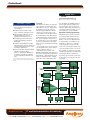
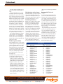
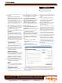
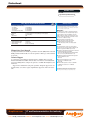
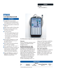
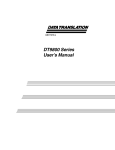
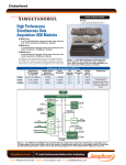
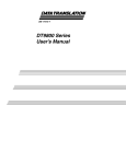
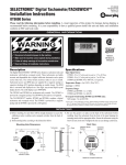
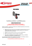
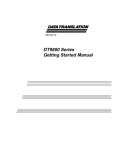
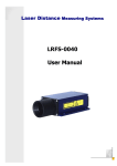
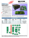
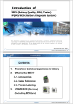
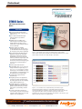
Datasheet
Compatible Windows Software
Data Acquisition Software Made Easy.
DT9805 Series
USB Thermocouple Measurement
Modules
Key Features
■ Easy plug-and-play thermocouple
measurements outside of the PC using
USB 2.0 or 1.1.
■ Up to 7 differential thermocouple
channels and one CJC channel
per module*.
■ Scalable design for adding more
channels (up to 889 thermocouples).
Simply add more modules to your
system using a single USB port and one
or more USB hubs.
■ Software support for multiple
thermocouple types (B, E, J, K, N, R, S,
T). Mix and match thermocouple types
by configuring each channel separately.
■ Free DT Thermocouple Measurement
application (SP1305) for immediate
temperature measurements with no
programming. Just connect to the PC,
connect your thermocouple inputs, and
run! Linearized temperature measurements, based on the thermocouple types
you specify, are returned in degrees
C, F, or K.
■ Thermocouple break detection.
■ Programmable gains of 1, 10, 100, and
500 per channel for input ranges of +/10 V, +/- 1 V, +/- 0.10 V, and +/- 0.020 V.
Autoranging is also available (for singlevalue operations) to automatically select
the gain based on your input range.
■ 2, 16-bit analog output channels
(DT9806 only).
■ 8 Digital input lines. The digital lines
can also be clocked synchronously at
the analog input rate for time-stamping
analog data and digital events.
■ 9 Digital output lines, including one
dynamic digital output line that can be
updated synchronously at the analog
input rate for synchronizing external
devices.
■ 2, 16-bit counter/timer channels for
event counting, frequency measurement,
continuous pulse output, one-shot, and
repetitive one-shot operations.
Amplicon.com
USB cable supplies
all power and data
for plug-and-play
operation
CJC on channel 0
Pluggable
screw
terminals
for
easy
connections
Directly connect thermocouples (B, E, J, K,
N, R, S, and T) and
other sensor types
Figure 1. The DT9805 Series modules are ideally suited for plug-and-play
thermocouple measurements. Pluggable screw terminal blocks allow you to connect
thermocouples and other sensor types directly to the module.
Figure 2. Use a DT9805 Series module with the free DT Thermocouple
Measurement application (SP1305) for immediate linearized temperature
measurements without programming. Simply connect the module to the PC using
the supplied USB cable, connect your thermocouple inputs, and run the
application. This view shows the temperature measurements of all 7 thermocouple
inputs and the CJC channel in a digital display.
IT and Instrumentation for industry
Sales: +44 (0) 1273 570 220 Website: www.amplicon.com Email: [email protected]
Datasheet
DT9805 Series
BUS: USB
Type: Thermocouple Measurement
Key Features - Continued
■ 500 Volt galvanic isolation maximizes
analog signal integrity and protects
your computer.
■ Flexible acquisition modes (singlevalue, continuous, and triggered scan).
■ High resolution 16-bit A/D converter
with throughputs as high as 50
kSamples/second (gains of 1 or 10).
■ Selectable trigger and clock sources
(software and digital) for acquiring
analog data.
■ Combines with DT Measure Foundry,
Data Translation’s powerful software for
creating test and measurement, control,
and analysis applications.
■ Ships with the Data Acquisition OMNI
CD, which includes Ready-toMeasure™ applications, WDM drivers
for Windows 2000/XP, an evaluation
version of DT Measure Foundry, and
more.
*You can directly connect other sensor types, such as
pressure, accelerometer, and other measurement inputs,
as well.
Overview
The DT9805 Series brings true plug-andplay temperature measurements to PCs
with USB 2.0 or 1.1 ports. Simply attach
the DT9805 Series module to the PC
using the supplied USB cable, directly
connect up to 7 thermocouples to the
screw terminals on the module, and run
the free DT Thermocouple Measurement
application (SP1305). Linearized temperature data is returned in degrees C, F, or
K. You don’t have to open your computer
or do any programming. It’s that simple.
All power is provided from the USB cable
to the PC.
If you’d rather create a custom application, the DT9805 Series offers a variety of
software solutions to help you.
The DT9805 Series consists of the
DT9805 and DT9806 modules. Both modules feature a Cold Junction Compensation
(CJC) channel, 7 differential analog input
channels, 8 digital input lines, 9 digital
output lines, and 2 counter/timer chanUSB
Interface
Specialized Analog Input Design
The DT9805 Series provides a CJC channel on analog input channel 0 that provides 10 mV/o C with an accuracy of 1o
(from 5o to 45o C). Seven differential analog input channels are available for connecting B, E, J, K, N, R, S, or T thermocouple inputs. (If you want to measure
other low-level analog input signals, such
as pressure and flow sensors, you can use
these channels to connect up to 16 singleended/pseudo-differential or 8 differential
analog inputs.) Thermocouple break
detection is also provided to set the value
to full-scale if an open circuit is detected
at the input.
Micro
Controller
Two 16-bit
User
Counter/Timers
Isolated
DC-DC and
Power Control
HighSpeed
Isolated
Data
Path
500 Volt Isolation Barrier
Dynamic
Digital
Output
Clock
Gate
Out
nels. In addition, the DT9806 provides 2
analog output channels for high-resolution, single-value output operations. To
add more channels (up to 889 thermocouples), simply add more modules to your
system using one or more USB hubs.
Isolated
Power
Isolated Side
Control
Logic
Channel Gain
List (32 Entries)
8 Digital
Outputs
CJC
7 Thermocouples
(16SE/8DI
Analog
Inputs)
Analog
Input MUX
Programmable
Gain Amplifier
(x1, 10, 100,
500)
8
Digital
Inputs
16-Bit
A/D Converter
External Clock
and
Trigger Logic
Trigger
2048
Sample
FIFO
16-Bit D/A
Converter
(DT9806 only)
Channel 0 Channel 1
Clock
Figure 3. This block diagram shows all the subsystems and user-accessible signals of the
DT9805 Series modules.
Amplicon.com
IT and Instrumentation for industry
Sales: +44 (0) 1273 570 220 Website: www.amplicon.com Email: [email protected]
Datasheet
All analog inputs are multiplexed to a
single 16-bit analog-to-digital (A/D) converter.
Four programmable gains (1, 10, 100,
and 500) are provided to support input
signal ranges of +/- 10 V, +/-1 V, +/-0.10 V,
and +/-0.020 V. For thermocouple inputs,
which are typically in the range of 20 mV,
DT9805 Series modules provide a dynamic range of 100,000:1 (100 db) to ensure
that the input signals are amplified to the
full +/-10 V range of the A/D converter
and digitized to 16 bits for maximum
accuracy. Each channel is configurable,
allowing you to mix and match input signals according to your needs. In addition,
DT9805 Series modules support autoranging, where the software can determine the
appropriate gain based on the input range
you specify (in single-value mode).
The maximum sampling rate depends
on the gain that is used: 50 kSamples/s
when the gain is 1 or 10, 10 kSamples/s
when the gain is 100, and 2 kSamples/s
when the gain is 500. The minimum sampling rate is 0.75 Hz.
Flexible Acquisition Modes
Using the DT9805 Series, you can acquire
a single sample from a single analog input
channel or multiple samples from multiple analog input channels. A 32-location
channel-gain list gives you the flexibility
to sample non-sequential analog input
channels, analog input channels with different gains, and digital inputs with the
analog input channels you want at the
A/D sample rate.
The DT9805 Series provides two ways to
cycle throught the channel-gain list:
• Continuous scan mode – Choose this
mode if you want to accurately control
the period between conversions of individual channels in a channel-gain list.
• Triggered scan mode – Choose this
mode if you want to accurately control
both the period between conversions of
individual channels in a channel-gain
list and the period between each scan,
or cycle, through the channel-gain list.
This mode is useful when synchronizing or controlling external equipment or
when acquiring a buffer of data on each
trigger or retrigger.
Amplicon.com
change state as an analog input channel is
read.
High-Resolution Analog Outputs
The DT9806 module provide two DC-level
analog output channels for single-value
operations. A 16-bit digital-to-analog converter provides high-resolution output values with an output range of +/- 10 V.
Flexible Digital I/O Lines
DT9805 Series modules feature 8 digital
input lines for single-value operations.
You can also read all the digital input
lines simultaneously with the analog
input channels at the A/D clocked rate.
The digital input lines can be clock separately as the only channel in the channelgain list at up to 50 kSamples/second.
Nine digital outputs are provided. The
digital outputs have sufficient current
capability to drive external solid-state
relay modules (sink 12 mA and source 12
mA). Eight of these digital outputs are
provided for single-value operations. A
dynamic digital output line is also provided for synchronizing external devices.
You can program the value of this line to
Programmable Clocks and
Triggers
For starting analog input measurements,
you can select either an internal or external trigger source. Select the internal trigger to start the operation based on a software command. Select an external trigger
to start the acquisition based on an external event. To use the external trigger, connect a TTL-level signal to the screw terminal of the module labeled External A/D
Trigger. The trigger occurs on the rising
edge of this signal.
For pacing analog input measurements,
you can select either the internal clock
source provided by the module or an
external clock source. An external clock is
useful when you want to pace acquisitions at rates not available with the internal clock or when you want to pace at
uneven intervals. To use an external
clock, connect a TTL-level signal to the
screw terminal of the module labeled
External A/D Sample Clock In.
User Connections
Pin
Number
Signal Description
Pin
Number
Signal Description
1
2
3
4
5
6
7
8
9
10
11
12
13
14
15
16
17
18
19
20
21
22
23
24
25
26
27
Analog Input 00/CJC Circuit
Analog Input 08/00 Return
Analog Input 01
Analog Input 09/01 Return
Analog Input 02
Analog Input 10/02 Return
Analog Input 03
Analog Input 11/03 Return
Analog Input 04
Analog Input 12/04 Return
Analog Input 05
Analog Input 13/05 Return
Analog Input 06
Analog Input 14/06 Return
Analog Input 07
Analog Input 15/07 Return
Isolated Analog Ground
Amp Low
Analog Output 0+
Analog Output 0 Return
Analog Output 1+
Analog Output 1 Return
Isolated Digital Ground
External A/D Trigger
External A/D Sample Clock In
Isolated Digital Ground
Isolated +5 V Out
28
29
30
31
32
33
34
35
36
37
38
39
40
41
42
43
44
45
46
47
48
49
50
51
52
53
54
Digital Input 0
Digital Input 1
Digital Input 2
Digital Input 3
Digital Input 4
Digital Input 5
Digital Input 6
Digital Input 7
Isolated Digital Ground
Isolated Digital Ground
Digital Output 7
Digital Output 6
Digital Output 5
Digital Output 4
Digital Output 3
Digital Output 2
Digital Output 1
Digital Output 0
Dynamic Digital Output
Isolated Digital Ground
External Gate 1
User Counter Output 1
User Clock Input 1
Isolated Digital Ground
External Gate 0
User Counter Output 0
User Clock Input 0
IT and Instrumentation for industry
Sales: +44 (0) 1273 570 220 Website: www.amplicon.com Email: [email protected]
Datasheet
DT9805 Series
BUS: USB
Type: Thermocouple Measurement
Conversions start on the rising edge of
this signal.
Multifunction Counter/Timers
DT9805 Series modules feature two 32-bit
user counter/timers that you can use for
event counting, frequency generation
(continuous pulse output), one-shot, and
repetitive one-shot operations. You can
connect or cascade counters together
either in software or by external connections to the screw terminals of the module. Programmable gates, clocks, and output signals are also supported.
500 V Galvanic Isolation Protects
Your Data
Computers are susceptible to groundspikes through any external port. These
spikes can cause system crashes and may
even cause permanent damage to your
computer. DT9805 Series modules feature
500 Volts of galvanic isolation to protect
your computer from ground-spikes and to
ensure a reliable stream of data.
User Connections
DT9805 Series modules provide pluggable screw terminal blocks for connecting all signals. You can remove these
screw terminal blocks for easy wiring. Pin
assignments are clearly marked on the
module for quick setup.
els – from programmers to application
users – the ability to access the functionality of the DT9805 Series modules.
Free Data Acquisition OMNI CD
The DT9805 Series ships with the Data
Acquisition OMNI CD, which includes
WDM device drivers for Windows
2000/XP, the SDK, quick start applications, and an evaluation version of DT
Measure Foundry.
Free DT Thermocouple Measurement
Application
For real-time measurement and display of
linearized thermocouple data without
programming, use the free DT
Thermocouple Measurement application
(SP1305), available from the Download
Software link at www.datatranslation.com.
The DT Thermocouple Measurement
application provides the following features:
• Plug and play operation with the
DT9805 Series.
• Automatically detects the module and
configures the device driver.
• Supports 2-wire thermocouple inputs.
• Allows you to specify the thermocouple
type (B, E, J, K, N, R, S, and T) for each
channel.
• Provides a digital view of live signals
showing the temperature of each thermocouple input as well as the CJC
channel, shown in Figure 2.
• Provides a graphical view of live signals
in a chart recorder display, shown in
Figure 4, for analysis.
You can set up the chart to display each
thermocouple signal in its own band or
all thermocouple signals in one band. In
addition, you can set up the chart display to automatically scale the y-axis
based on your input signal (autoscale)
or scale the y-axis to the first input signal in your buffer (capture-scale). Other
options are provided for showing or
hiding the reference cursors, holding
the display from updating, printing the
display, and saving the results to disk.
Scrolling, panning, and zooming functions allow you to see the entire signal
in one display.
• Logs data directly to disk for post-analysis in Excel or other programs.
USB 2.0 Compatibility
DT9805 Series modules are fully compatible with USB 2.0 and USB 1.1. USB 2.0 is
both forward and backward compatible
with USB 1.1, resulting in a seamless
transition process for users. A USB cable
is shipped with the DT9805 Series for
connecting the module to the USB 2.0 or
USB 1.1 port of your computer.
Power
All power is provided through the USB
cable to the module. No external power
supply or battery is required.
Many Software Choices
Data Translation provides a number of
software choices to allow users of all lev-
Amplicon.com
Figure 4. The Chart view of the DT Thermocouple Measurement application allows you to
log thermocouple data to a chart recorder display and to a file for further analysis in Excel or
other programs. In this example, the temperature of a T-type thermocouple and the CJC
channel are displayed.
IT and Instrumentation for industry
Sales: +44 (0) 1273 570 220 Website: www.amplicon.com Email: [email protected]
Datasheet
• Loads saved signal files into the chart
recorder display for analysis.
Any combination of thermocouple
types can be connected to one module –
for example, use three J-types, two Ttypes, and two K-types – all at the same
time.
Customize Applications Using DT
Measure Foundry
If you need more flexibility than the DT
Thermocouple Measurement application
provides, use DT Measure Foundry version 4.0.6, available soon, to modify the
application or to create your own application. DT Measure Foundry is a powerful
software package that allows non-programmers to create test and measurement,
control, and analysis applications. It
includes a Thermocouple Linearization
panel specifically for dealing with thermocouples. This panel automatically
adjusts for the CJC channel, linearizes raw
analog input data based on the thermocouple types you specify, and returns the
data in degrees C, F, or K.
Save Programming Time and Protect
Your Investment with DT-Open Layers
Virtually all Data Translation data acquisition boards, including the DT9805 Series,
are compatible with the DT-Open Layers
software standard. This means that if your
application was developed with one of
Data Translation’s software products, you
can easily upgrade to a new Data
Translation board. Little or no reprogramming is needed. For example, if you are
currently using a DT301 on the PCI bus,
upgrading to a DT9805 Series module on
the USB bus is simple – just load and
configure the new driver and you’re done.
Since the DT9805 Series is supported
by DT-Open Layers, you can also use
LabVIEW® or DTx-EZ™ with DT9805
Series modules.
Analog Inputs
Thermocouple Measurement
Number of analog input channels
Differential:
Single-ended/pseudo-differential:
CJC Voltage @ 25°C
CJC Accuracy
CJC Warm-up time
Thermocouple break detection current
Resolution
Channel-gain list
Input FIFO size
Input gains
Input range
Drift
Zero:
Gain:
System Accuracy (Full Scale)
Input impedance
Input bias current
Common mode voltage
Maximum input voltage
Channel acquisition time
A/D conversion time
Common mode rejection
DC Accuracy
Nonlinearity (integral)
Differential nonlinearity
A/D converter noise
Channel-to-channel offset
AC Accuracy
Effective number of bits (ENOB)
Total harmonic distortion (THD)
Channel crosstalk
Clocking and trigger input
Maximum A/D pacer clock
Single analog input throughput
Multiple analog input throughput
Single digital input channel
Minimum A/D pacer clock throughput
External A/D sample clock
Minimum pulse width:
Maximum frequency (analog inputs):
Maximum frequency (digital inputs only):
External digital (TTL) trigger
High-level input voltage:
Low-level input voltage:
Minimum pulse width:
Maximum frequency:
8 (7 thermocouple inputs, 1 CJC)
16
+0.250 V
+1° from 5° to 45° C
10 to 20 minutes*
+50 nA (high-side differential)
outputs full-scale for gains greater than 1,
or 2.5 V for gains of 1
16 bits
32 locations
2048 samples
1, 10, 100, 500
±10, 1, 0.1, 0.02 V
±25 + (5 µV*Gain)/°C
±20 ppm/°C
0.01% @ Gain=1
0.02% @ Gain=10
0.03% @ Gain=100
0.04% @ Gain=500
100 MΩ, 10 pF, Off
100 MΩ, 100 pF, On
±10 nA
±11 V maximum (operational)
±40 V maximum (protection)
6 µs (gain = 1), 250 µs (gain = 500)
8 µs
>74 db
±4 LSB
±1.2 LSB (no missing codes)
0.4 LSB rms
±40.0 µV
14.1 bits
–90 dB typical
–80 dB @ 1 kHz
50 kS/s @ 0.01% accuracy at a gain of 1-10
50 kS/s @ 0.01% accuracy at a gain of 1-10
10 kS/s @ 0.03% accuracy at a gain of 100
2 kS/s @ 0.04% accuracy at a gain of 500
Maximum A/D rate
0.75 S/s
600 ns (high); 600 ns (low)
750 kHz
Maximum A/D rate
2.4 V minimum
0.8 V maximum
600 ns (high); 600 ns (low)
750 kHz
*Using the DT9800 Series control panel applet, you can choose to keep power on to the
module allowing the analog circuitry to stabilize.
Amplicon.com
IT and Instrumentation for industry
Sales: +44 (0) 1273 570 220 Website: www.amplicon.com Email: [email protected]
Datasheet
Analog Outputs
DT9806
Number of analog output channels
Resolution
Output range
Output throughput
Error
Gain:
Zero:
Current output
Output impedance
Capacitive drive capability
Nonlinearity (integral)
Differential linearity
Protection
Power-on voltage
Settling time to 0.01% of FSR
2 (voltage output)
16 bits
±10 V
Single value (system dependent)
±6 LSBs
Software adjustable to 0
±5 mA minimum
0.3 Ω typical
0.001 µF (no oscillators)
±4 LSB s
±1.0 LSB (monotonic)
Short circuit to Analog Common
0 V ±10 mV
50 µs, 20 V step;
10.0 µs, 100 mV step
2 V/ µs
Slew rate
Digital I/O
Number of lines
Inputs
High-level input voltage:
Low-level input voltage:
High-level input current:
Low-level input current:
Maximum internal pacer clock rate
(single digital channel):
Port A
Port B
Dynamic Digital Output
8 input
8 output
1 output
2.0 V minimum
0.8 V maximum
3 µA
–3 µA
Maximum A/D rate
Outputs
Output driver high voltage:
Maximum A/D rate
2.4 V minimum
(IOH = –1 mA);
0.5 V maximum
(IOL = 12 mA)
Output driver low voltage:
Counter/Timer
Number of counter/timer channels
Clock Inputs
High-level input voltage:
Low-level input voltage:
Minimum pulse width:
Maximum frequency:
Gate Inputs
High-level input voltage:
Low-level input voltage:
Minimum pulse width:
Counter Outputs
Output driver high voltage:
Output driver low voltage:
Amplicon.com
2
2.4 V minimum
0.8 V maximum
600 ns (high); 600 ns (low)
750.0 kHz
2.4 V minimum
0.8 V maximum
600 ns (high); 600 ns (low)
3.0 V minimum (1 mA source)
0.4 V maximum (2 mA sink)
IT and Instrumentation for industry
Sales: +44 (0) 1273 570 220 Website: www.amplicon.com Email: [email protected]
2.4 V minimum
(IOH = 1 mA);
0.5 V maximum
(IOL = 2 mA)
Datasheet
DT9805 Series
BUS: USB
Type: Thermocouple Measurement
Power, Physical, and Environmental Specifications
Power (provided by the USB cable)
+5 V standby
+5 V enumeration
+5 V power on
+5 V isolated power out (TB 27)
Physical
Dimensions:
Weight:
I/O connector:
Certification and compliance
Environmental
Operating temperature range:
Storage temperature range:
Relative humidity:
0.5 µA maximum
100 mA maximum
500 mA maximum
10 mA maximum
6.5 inches (length) by 4.5 inches (width) by 1.4 inches (depth)
9 oz. (255 grams)
USB
FCC Part 15 Class B verified; will not compromise FCC compliance of host computer
CE
0°C to 55°C
–25°C to 85°C
To 95%, noncondensing
DT9805 Series User’s Manuals
A getting started and user’s manual are provided in electronic (PDF) format on the CDROM provided with the module. You can also purchase a hard copy of these manuals,
if you wish.
Technical Support
As you develop your application, technical support is available when you need it.
Extensive information is available 24 hours a day on our web site at www.datatranslation.com, including drivers, example code, pinouts, a searchable KnowledgeBase, and
much more.
Support is also available from your point of purchase. Telephone support is free for
the first 90 days; you can also request complimentary support via e-mail or fax at any
time.
Amplicon.com
Ordering Summary
All Data Translation hardware products are covered by a 1-year
warranty. For pricing information, see a current price list, visit our
web site, or contact your local reseller.
DT9805 Series
Each DT9805 Series module is shipped with the Data
Acquisition Omni CD, which includes DT-Open Layerscompliant drivers for Microsoft Windows 2000/XP,
Ready-to-Measure software, and comprehensive user’s
manuals in PDF format. Manuals are available in hardcopy form for an additional charge.
■ DT9805 USB function module with 16-bit,
50 kS/s analog inputs, and no analog outputs
■ DT9806 USB function module with 16-bit,
50 kS/s analog inputs, and 2, 16-bit analog outputs
Software
The following products include a copy of the software,
a single-user license, and a user manual (in PDF form). All
software is supplied on CD-ROM, except as noted.
■ DT Thermocouple Measurement application for linearized
temperature data without programming
SP1305, free and available from the Download Software
link on our web site (www.datatranslation.com)
■ DT Measure Foundry test and measurement application
builder for Windows 2000/XP
SPI300-CD
■ DTx-EX visual programming tools for Visual Basic
and Visual C++ for Windows 2000/XP
SP0970-CD
■ DT-LV Link data acquisition connection to LabVIEW
for Windows 2000/XP, on 3.5 in. 1.4 MB disk
SP0810-CL
© Copyright 2004 Data Translation, Inc. All rights reserved.
All trademarks are the property of their respective holders.
Prices and specifications subject to change without notice.
IT and Instrumentation for industry
Sales: +44 (0) 1273 570 220 Website: www.amplicon.com Email: [email protected]