1
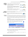
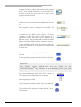
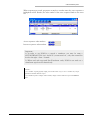
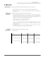
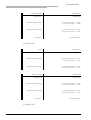
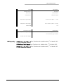
© NOTOCORD Systems
DOC10s
1. Applications
The Digital Output Controller (DOC10s) software module allows control over various
hardware devices. Some of its common applications are the control of stimulators,
perfusion systems or aerosol delivery. Its user-friendly interface allows you to program the
series of events as they should occur in the framework for your experimental protocol.
Warning:
CAUTION: THIS SOFTWARE PRODUCT HAS NOT BEEN VALIDATED FOR
USE ON HUMAN.
2. Intended use
DOC10s module makes it possible to define the
protocol of an experiment by planning and by
setting the parameters for various sequences of
signals likely to follow one another within the
framework of an experiment, and these signals
can be :
• stimulation signals,
• control signals, or "output" signals since they come out through the output channel.
During the stimulation sequences, the software module controls the stimulation which
materializes by periodic pulses of which the period and the width are adjustable.
During the output sequences, the module sends out control commands which materialize
by single, short pulses of which the width is not adjustable.
During the wait sequences, the module sends out wait commands which materialize by no
signal emission.
Sequences likely to follow one another are limited to 99.
November 28, 2007 Edition
1/8
© NOTOCORD Systems
Stimulator
control and
stimulation
signals
To control a stimulator, one must define the stimulation signal.
To define the T period, click in the "Period(ms)" column in
the required line and fill the right value in the field. Values
are expressed in milliseconds.
To define the TD width when the stimulation signal logical
level is high, click in the "Width(µs)" column in the
required line and fill the right value in the field. Values are
expressed in microseconds.
To define the duration of the sequence, click in the
"Duration(s)" column in the required line and fill the right
value in the field. Values are expressed in seconds.
Equipment
control and
output signals
Output sequences need no adjustments. Equipment control simply responds to orders
based on a short, single signal transition.
Defining a
protocol
Some experiments could require stimulator control and the control of an equipment at
the same time. Therefore, it is necessary to define the sequences of each experiment.
For Action Potential measurements, for example, it may be recommended to program
wait sequences between stimulation sequences, after or while fibers are being washed.
Moreover, the output sequences command equipment controls such as drug or
cleaning pumps.
However, you can select specific output channels for these sequences.
Click in the "Channel" column in the required line and select a channel
in the list.
Each line defines the characteristics for a sequence, and the DOC10s software module can
generate three types of sequences : wait sequences, stimulation sequences and output
sequences. Sequences follow one another. The whole protocol can be repeated.
To create a sequence, click the "Insert" icon (button). After the icon is
clicked, a new line is created and highlighted in blue, and the default
values for the sequence are shown.
The next step consists in defining the sequence and its configuration. For each sequence a
new line is created, and each line is divided in eight columns. Information concerning
sequence's configuration is displayed in each column.
There can be a maximum of 99 sequences.
During an experimentation which requires a stimulator, you can for example create
stimulation and wait sequences.
November 28, 2007 Edition
2/8
© NOTOCORD Systems
To define a sequence, click the line related to the sequence
in the "Type" column, then select a type. Default "Type"
value for sequences is : Wait.
In order to prepare the entire protocol, the type of each
sequence must be selected.
As the module is started and the sequences follow one
another, the type of each sequence is displayed in the status
bar.
Each sequence is given a number by the module. This
number is the sequence order number.
A comment can be added to each sequence. To enter a
comment, click the line related to the sequence in the
"Comment" column, then enter a short comment in the
field that appears. This comment will eventually be used to
define event marker labels when the sequence is activated.
As the module is started and as the sequences follow one
another, the comment of each sequence is also displayed in
the status bar.
To delete a sequence, simply click the "Delete" icon
(button).
To start sequencing, simply click the "Start" icon (button).
Important :
The DOC10s software module start does not depend on main
NOTOCORD-hemTM start. Therefore, it is recommended to first start signal
acquisition, and next, start the stimulator.
Start times are displayed in the "Start Time" column. For
each sequence (in each line), there is a start time.
A start time is defined for each sequence according to time
when sequencing is started.
To stop sequencing, simply click the "Stop" icon (button).
To loop through the sequences, simply click the "Loop"
icon (button).
November 28, 2007 Edition
3/8
© NOTOCORD Systems
When sequencing is started, progression is simple to visualize since the active sequence is
highlighted in blue. Besides, the order number of the active sequence blinks in the status
bar.
Active sequences order numbers.
Inactive sequences order numbers.
Important :
1) In order to use DOC10s to control a stimulator, you must be using a
NOTOCORD® DT-P6 (ref.: hrd-1015 ) connection box ; only this connection
box has the right « Stim » channel.
2) When used with supported DataTranslation cards, DOC10s can send out a
stimulation signal on one channel only.
Remarks :
1) To visualize outgoing signals, simply proceed the same way you do to visualize any output
signal from a module with an output.
2) To visualize sequence changes with a marker, simply connect DOC10s output with KBD30a
input.
November 28, 2007 Edition
4/8
© NOTOCORD Systems
3. Features
Inputs and
outputs
The DOC10s module has no input and only one output. It
is an event type output and is discrete.
Period, width,
step and
duration of
stimulation
and wait
sequences
T period for pulses in stimulation sequences goes from the
start of a pulse to the start of the next pulse.
Range is from 20ms to 100s in steps of 1ms.
Output
TD width ange is from 0.1ms to 10ms in steps of 1µs.
Minimum duration for a sequence is 1 s.
Maximum duration for a sequence is 10 hours.
If a sequence ends in the midst of a pulse, pulse level is set back to 0.
Width and
duration of
output
sequences
T durations in output sequences do not change. This pulse
is only meant for equipment that responds to orders based
on a short, single signal transition.
T duration of an output sequence lasts the time needed to
start the next sequence and is approximately equal to the
TD width of the pulse. Pulse begins as soon as the sequence is started.
TD width is 50 ms.
Output signals can only come out on one channel at a time. To get something close to
coming out on multiple channels, several output sequences should follow each other, and
they should be configured for signals to come out on different channels.
Precision
• DT300 and DT3010 series :
Precision for period and width of stimulation signals depends on the precision of the clock
on the acquisition card.
Precision for the width of the output signal depends on the operating system. Equipment
controled by these signals must not depend on a precise pulse width.
CPU load
CPU load due to DOC10s software module is not significant.
November 28, 2007 Edition
5/8
© NOTOCORD Systems
4. Material
Requirements
In order to work, DOC10s software module should run on a system with :
• DT9800 BNC Box and a connector provided by NOTOCORD® Systems,
• DT301 or DT3010 card and the NOTOCORD® DT-P6 (ref.: hrd-1015 )
connection box.
Cables and
connections
Cables and connections depend on the acquisition card used :
• on the DT301 and DT3010 series, there are 8 input /output channels among the
16 digital channels. These channels are numbered 9 to 16. As soon as the DOC10s
module is started, all these channels become output channels only. However, it is
possible to acquire the outgoing signals with these cards.
Stimulation signals come out on the clock channel.
Output signals come out on digital channels.
Caution : Connecting DT301 cards to the NOTOCORD® DT-P6 (ref.: hrd-1015 )
connection box requires only one cable, but two cables are required to connect
with DT3010 cards.
• on DT9800 series, there are 8 input channels and 8 output chanels. To acquire
output signals, simply connect output and input channels.
Isolation
output-stage
Characteristics depend on the acquisition card used :
• DT300 series :
Outputs
Port A
Port C
Output driver :
FCT2574 (TTL)
FCT2574 (TTL)
ASIC (TTL)
Output driver high voltage :
2.4 V minimum
(IOH =-15 mA)
2.4 V minimum
(IOH =-15 mA)
2.4 V minimum
(IOH = 4 mA)
0.5 V maximum
(IOL = 12mA)
0.5 V maximum
(IOL = 12mA)
0.8 V maximum
(IOL = 4mA)
Output driver low voltage :
November 28, 2007 Edition
Port B
6/8
© NOTOCORD Systems
Stimulation Output
Specifications
Output driver :
ALS244 (TTL)
Output driver high voltage :
2.4 V minimum (IOH =-15 mA);
2.4 V minimum (IOH = -3 mA)
Output driver low voltage :
0.5 V maximum (IOH = 24 mA);
0.5 V maximum (IOH = 12 mA)
Termination :
22 Ω series resistor
• DT3010 series :
Output
Specifications
Output driver :
ALS652 (TTL)
Output driver high voltage :
2.0 V minimum (IOH =-15 mA);
2.4 V minimum (IOH = -3 mA)
Output driver low voltage :
0.5 V maximum (IOH = 24 mA);
0.4 V maximum (IOH = 12 mA)
Stimulation Output
Specifications
Output driver :
ALS244 (TTL)
Output driver high voltage :
2.0 V minimum (IOH =-15 mA);
2.4 V minimum (IOH = -3 mA)
Output driver low voltage :
0.5 V maximum (IOH = 24 mA);
0.4 V maximum (IOH = 12 mA)
Termination :
22 Ω series resistor
• DT9800 series :
November 28, 2007 Edition
7/8
© NOTOCORD Systems
Output
Specifications
Nomber of lines :
8 (Port B)
Termination :
22 kΩ resistor
Output driver :
74HCT244 (TTL)
Output driver high voltage :
2.4 V minimum (IOH = -1 mA)
Output driver low voltage :
0.5 V maximum (IOH = 12 mA)
Diodes EMF
Yes
Stimulation Output
Specifications
Output driver high voltage :
3.0 V minimum @ 1 mA Source
0.4 V maximum @ 2 mA Sink
Output driver low voltage :
Bibliography
DT3010 Series User’s Manual Data Translation Inc, Marlboro MA, 4th ed. March 2002.
DT300 Series User’s Manual Data Translation Inc, Marlboro MA, 7th ed. March 2002.
DT9800 Series User’s Manual Data Translation Inc, Marlboro MA, 7th ed. March 2002
November 28, 2007 Edition
8/8