1
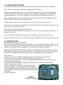
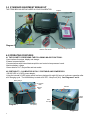
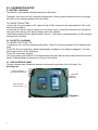
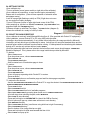
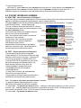
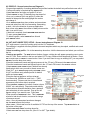
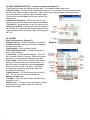
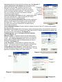
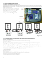
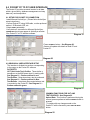
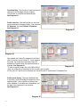
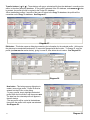
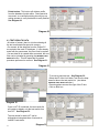
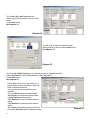
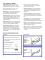
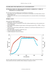
User Manual
Micro-Cal™
Model 869
1-800-257-3872 Toll Free
1-978-264-0292 FAX
www.setra.com Web Site
Table of Contents
1.0 SAFETY INSTRUCTIONS………………………………………….……
1
2.0 INTRODUCTIONS……….…………………………………….…………
1
3.0 STANDARD EQUIPMENT………………………………………………
2
4.0 OPERATING FEATURES
4.1 Pocket PC……………………………………………………..
4.2 Portability……………………………………………………..
2
2
5.0 CALIBRATION SETUP
5.1 Battery Charging…………………………………...………..
5.2 Pocket PC Charging…………………………….…………..
5.3 User Interface Panel………………………………………...
5.4 Getting Started……………………………………………….
5.5 Backup/Restore Data………………………………………..
3
3
3
4
4
6.0 POCKET PC INTERFACE SCREENS
6.1 Real Time……….…………………………………...………..
6.2 Test…………………..…………………………….…………..
6.3 Profile………………..………………………………………...
6.4 Unit Under Test (UUT)….…………………………………...
6.5 Reference……………………………………………………..
6.6 System………………………………………………………...
5
5
6
6
7
7
7.0 UNIT UNDER TEST SETUP
7.1 Wiring Setup……….…………………………………...……
9
8.0 CALIBRATING/TESTING A TRANSDUCER…………………………..
9
9.0 POCKET PC TO PC USER INTERFACE……………………………....
9.1 Setup…………….…………………………………...………..
9.2 Graphic User Interface………………………….…………..
9.3 Test Results Data………………….………………………...
10
10
13
10.0 GLOSSY OF TERMS & SPECIFICATION DERIVATIONS……..…
15
1.0 SAFETY INSTRUCTIONS
Use the calibrator only as specified in the manual, otherwise the protection provided may be impaired.
Do not operate the calibrator in explosive gas, vapor or dust environments.
The calibrator is designed to operate from 24 VDC internal battery source or from the AC adapter that is
Included. Additionally, a smart battery charging system is supplied for charging the internal Nickel Metal
Hydride (NiMH) battery. Do not use AC adapters or chargers other than those supplied with the unit.
When charging the battery from the included battery charger the AC adapter must be plugged into the 24
VDC port on the left side of the unit to enable charging.
If supply external excitation to the Unit Under Test is a measure mode, do not exceed 30 VDC.
There are no user serviceable parts internally, removing the internal cover will void warranty. Return the unit
to the factory for re-certification or repair.
BEST PRACTICES FOR CALIBRATOR OPERATION:
Use the shortest length of tubing from the calibrator to the Unit Under Test, during pressure testing avoid
vibration of the tubing.
Avoid movement of the calibrator during operation, avoid locating in a high vibration environment.
Allow the calibrator to warm-up for one (1) hour before use. The calibrator can be turned on during transport.
2.0 INTRODUCTION
DOCUMENTING PROCESS CALIBRATOR:
The Setra Micro-Cal Model 869 is a pressure generating, very low pressure documenting calibrator. The calibrator has been designed and optimized to meet the needs of our customers for a capable system for the
calibration, troubleshooting and documentation of very low pressure measuring information.
The design of the Model 869 exploits years of experience in the calibration of Setra transducers, as well as
NASA patented and Setra exclusive licensed technology. The Pocket PC user interface provides a familiar
“state-of-the-art” application of computer technology and an upgrade path for future developments.
Major Features:
-Pocket PC user interface, capable of storing thousands of Units Under Test (UUT) data files.
-Portable, battery powered system, capable of full operation for eight (8) hours.
-Closed loop pressure control which is immune to the effects of ambient pressure perturbations, (doors
closing, people moving around).
-Very low internal reference pressure standards, which are matched to the UUT, pressure ranges.
-Auto zero pressure “tare” function.
-Ability to source power to the UUT, or external power supply.
-Strip chart capability for troubleshooting leak and drift conditions.
-Micro-stepping pressure control capable of precise generation and
pressure control in the micro inch of water column pressure ranges.
-Leak testing
-Volume measurement
Diagram 1
Standard Equipment
1
3.0 STANDARD EQUIPMENT BREAKOUT
THE ITEMS BELOW ARE INCLUDED IN YOUR CALIBRATOR:
Calibrator
AC Power
Adapter
Diagram 2
Pocket PC Document
and cables
Battery Charger
Pneumatic Fittings & Tubing
Electronic Test Lead Kit
4.0 OPERATING FEATURES
4.1 THE POCKET PC PERFORMS THE FOLLOWING MAJOR FUNCTIONS:
-User interface for setups, display and storage.
-External communications
-Communications with internal data acquisition and control microprocessor board.
-Monitors battery voltage
-Stores data for UUT, test profiles and test results.
4.2 PORTABILITY – CALIBRATOR IS FULLY PORTABLE AND POWERED BY:
-120/240 VDC to 24 VDC power adapter.
-Using the internal 24 VDC battery which has been designed for eight (8) hours of continuous operation after
a full charging cycle. The NiHM battery is rated at 24 VDC, 4 Amp hour (AH). See Diagrams 3 and 4.
Battery Charger
User Interface
Panel
Pocket PC
Keyboard
Input
On/Off
Switch
120V/
24VDC
Input
Diagram 3
Power
Fuse (4A)
Current Loop
Fuse (63mA)
Serial
Port
Diagram 4
2
5.0 CALIBRATION SETUP
5.1 BATTERY CHARGING:
The calibrator is assembled, calibrated and tested at the factory.
The battery, as received, will be in a partially charged state. Before operation please be sure to fully charge
the battery to get maximum portable use of the device.
TO CHARGE THE BATTERY:
-Connect the AC power adapter to AC supply and the 24 VDC connector to the input labeled 24 VDC on the
left side of the calibrator.
-Connect the AC end of the Smart Charger to an AC power source, connect the other end (4 pin circular DIN
connector) of the charger to the battery charger input of the calibrator.
-Initial battery charging will take approximately 2-4 hours. If the battery is discharged below 20 VDC charging
overnight will be required.
5.2 POCKET PC CHARGING
TO CHARGE THE POCKET PC:
-If calibrator is not in use for extended periods of time, Pocket PC should be plugged into HP supplied power
cable.
-Pocket PC will only charge from calibrator when battery is charged or A/C adapter is plugged in. The main
power switch must be in the ON position.
-Pocket PC must remain charged.
-Should the battery on the Pocket PC become drained to the point that the device resets itself, please see the
Pocket PC Backup/Restore information on Page 6 of this manual.
5.3 USER INTERFACE PANEL
The user interface panel includes the pressure and electrical connections to the Unit Under Test.
See Diagram 5.
Optional UUT Mounting
8-32 UNF Threaded Inserts (2)
Power Switch
Pocket PC
Power Switch
High Pressure Port
Low Pressure Port
Diagram 5
3
5.4 GETTING STARTED
-Open calibrator top.
-Turn on calibrator power (power switch on right side of the calibrator).
-Once calibrator is powered up, re-zero function begins automatically,
Please wait for completion. (User will hear operation of solenoid valves
and stepper motor).
-Look for orange light (flashing or solid) on PDA (if light does not come
on, see section on battery charging.
-Turn on PDA power (button in upper right-hand corner of the PDA).
-After powering up, tap the icon labeled CALIBRATOR, (tap START MENU icon,
programs folder and CALIBRATOR icon).
-Software will start up with Real Time page. Tap VENT button (diagram 6)
to leave the calibrator in a ready to “hook-up” state.
Diagram 6
Vent Function
5.5 POCKET PC BACKUP/RESTORE
-Once calibrator is received, install Microsoft® ActiveSync ®. (Disc provided with Pocket PC equipment).
-After installation, connect Pocket PC to PC using USB cable provided.
-ActiveSync should start automatically, if not, please follow instructions for usage provided by Microsoft.
-ActiveSync will ask which type of partnership to setup. ActiveSync will recognize standard setup and the
required actions without automatic synchronization running. If backup/restore and interfacing the database
through a PC are the only actions required, select GUEST.
-Once the partnership type has been selected, the ActiveSync main screen should appear. CONNECTED
Should be displayed. If not, please refer to the usage instructions provided by Microsoft.
-To backup:
-Select TOOLS menu
-From drop-down menu, choose BACKUP/RESTORE
-Select BACKUP tab
-Press BACKUP NOW button
-Wait for status bar to fill and status page to close
-To restore:
-Select TOOLS menu
-From drop-down menu, choose BACKUP/RESTORE
-Select RESTORE tab
-Press RESTORE button
-A box will pop up requesting which Pocket PC to restore
-Press OK button
-Press RESTORE button on confirmation page and wait for status page completion
-To restore the file shortcut:
-Use the FILE EXPLORER PROGRAM on the Pocket PC to copy the shortcut from MYDEVICE/IPAQFILESTORE to
MYDEVICE/WINDOWS/STARTMENU/PROGRAMS.
-Press START button
-Select PROGRAM from list
-Select FILE EXPLORER from list of available programs
-Select ROOT DIRECTORY by pressing down arrow next to CURRENT DIRECTORY
-A list with drop down showing the path, select MYDEVICE.
-Select IFAQ file store directory
4
-Press and hold stylus to CALIBRATOR file (should be 36B for file size).
-A list of options will pop up, select COPY and return to root directory
-Start WINDOWS directory
-Select START MENU directory (scroll down using slide bar to right if necessary).
-Select PROGRAMS directory
-Scroll to bottom of list (using slide bar on right).
-Press and hold stylus to white area beneath last item in list.
-Select PASTE from pop up list
-To restore button shortcut:
-On Pocket PC, press START and select SETTINGS from drop down list. Select buttons from PERSONAL tab.
Highlight desired button (BUTTON 4 is factory default). Select PROGRAM to assign from drop down list. If
Calibrator program is not available, press OK, please be sure file shortcut has been restored.
6.0 POCKET INTERFACE SCREENS
6.1 REAL TIME – Screen instructions on Diagram 7.
-Real Time output is constantly updating and is used to see the existing output and existing pressure being
applied for calibration purposes and test purposes, (acts as a digital indicator).
-The HOLD SAMPLE button will take a filtered reading and freeze the display with that reading. To release,
Press the same button – release display hold.
Excitation to UUT
-The –FS, +FS button enters the selected UUT’s lowest
Tares Internal
and highest pressure input into pressure target box, and
Pressure Standard
Applied
call GO TO PRESSURE function.
Sets Pressure at -FS
Pressure
Range in UUT Profile
-Vent: Opens both positive and negative pressure
0 In. of W.C. (True Zero)
ports to each other and atmosphere.
Sets Pressure at +FS
Range in UUT Profile
UUT Output
-Tare: Tares reference and re-zero’s mechanical
Sets Pressure to 0
components in the controller.
Current Pressure Target
-Go to pressure: Calls controller to generate
Monitor/Control Mode
Terminal Based Error
Snapshot of Any
(%FS) Includes Zero
pressure point set in pressure target box.
Displayed Condition - Release
and Span Errors
-Halt: Stops process in action.
Vents Pressure to
Atmosphere
Bar Graph of
-Monitor/Control: Switches pressure generating
Halts Operation
Error (%FS)
mode into monitoring mode. Allows calibrator to
be used as pressure measurement device.
Diagram 7
6.2 TEST – Screen instructions on Diagram 8.
-Tap the TEST tab at the bottom of the page.
-Select desired UUT serial number ID from the drop
down box at the bottom of the page. If desired UUT
is not there, see section on creating a new UUT.
-View the PROFILE ID drop down box and confirm
that profile selected is the desired profile, if not,
select desired profile from drop down list.
-Select AS FOUND or AS LEFT radio button.
-Tap RE-ZERO and wait until completed.
-Tap DO TEST button
-To stop a test in process, tap the STOP button.
This will stop and cancel the test.
-Target pressure will be generated and data will be
automatically recorded at each pressure point.
Unit Under Test
(UUT) Identity
Stop
Profile ID
Do Test
Re-Zero
Record Data
Review Date
As Found/As Left
Test Selection
Target Pressure
Test
Screen
Diagram 8
Note: If the DISPLAY TEST RESULTS IN GRAPH OPTION is selected
– a graph will appear displaying pressure vs. error
after the pressure sequence has been completed.
-To record data – Tap RECORD TEST RESULTS button – a dialog box will appear and ask if you wish to save as
a text file (.txt) – Selecting YES will save data as an encrypted file and as a (.txt) file. Selecting NO will only
save it as an encrypted file. (Note: Text file is required to review data offline).
-To review data – tap REVIEW TEST RESULTS button.
5
6.3 PROFILE – Screen instructions on Diagram 9.
-Program has capability of creating additional test profiles besides the default test profiles that come with it.
-If new profile setup is required tap the PROFILE tab.
-Select NEW button and type new profile ID in box.
-Select PROFILE to copy, (if desired) from drop down list.
Profile ID
-Once you’ve entered your new profile ID, select the
number of data points box and highlight the number
Profile Type
Number of
and change it.
Perform
Leak
Test Points
Test
-Go to PROFILE TYPE drop down window and press down
Pressure
arrow and select from the list of ascending, descending
Target
Point
Output
or both – this is the direction of pressure application.
Target
Pressure
Note: when using BOTH, the number of data points must be
odd, it can not be even.
-If leak test is required, check PERFORM LEAK TEST box.
-To save, press SAVE button.
-To delete a profile, select PROFILE from list and
push DELETE button.
Diagram 9
6.4 UUT (UNIT UNDER TEST) SETUP – Screen instructions on Diagram 10.
UUT setup screen is used for inputting units into the UUT database.
The calibrator is supplied with many default instrument templates which may be copied, modified and saved
as new UUT.
-Select an existing profile – Go to the UUT ID drop down box, click the down arrow and select your unit from
the list.
-Create a new profile – Tap NEW button at bottom of page, a dialog box will appear prompting user to enter
new UUT ID#. Enter number in the box and select UUT to copy if desired from drop down list below. Press
OK to create new or CANCEL to cancel action. Note: If you don’t want to copy an existing UUT you may select
DEFAULT from the drop down menu.
-Enter the transducers lowest and highest pressure in the –FS and +FS boxes in the INPUT column.
-Enter the transducers lowest and highest output in the –FS and +FS boxes in the OUTPUT column.
-Select DEFAULT TEST PROFILE (many defaults are already
listed) select which one you want or create a new one.
(Save UUT, go to PROFILE page and create NEW, return
UUT ID
Box
to UUT and select newly created profile for default
profile and press SAVE).
Profile Template
ID
-Enter the required pressure set time at target
(in milliseconds, 99,999 max. and 0 min. – 5,000
Accuracy
UUT Input/Output
recommended). Pressure set time is time allowed
Setting Time
Specs (Ideal)
For
Data
at pressure point before data is acquired.
Acquisition
-Enter CONTROL STABILITY (in inches of water column, Pressure Stability
Max. Leak Rate
Required for
Allowable for
0.0003” min. and default). Required control stability Data
Acquisition
Pass/Fail
is the maximum allowable deviation from a pressure
Excitation
Level
point when data is to be acquired. Pop up box will
Delete UUT ID
New UUT
appear asking if you want to save. Press YES.
Save New
ID Setup
UUT ID
-Enter maximum LEAK RATE in box. This is PASS/FAIL
criteria for leak check function, measured in change
of pressure second.
Diagram 10
-Save – Once all parameters have been changed,
tap the SAVE button at the bottom.
-Delete a UUT – Select UUT from list of available UUT ID’s at the top of the screen. Tap DELETE button at
the bottom of the page.
-Select EXCITATION LEVEL from drop down list.
-Select UUT TYPE from drop down list, (See 8.1 for UUT Type details).
6
6.5 VIEW A REFERENCE SETUP – Screen instructions on Diagram 11.
-Tap the REF tab to view the different reference data – Tap on REF 1 or REF 2 radio button.
-Reference Setup – The Model 869 is shipped with either one or two internal reference transducers that
are referred to as REF 1 or REF 2 respectively. REF 1 is the lowest range and REF 2 is the highest range.
If only one reference is installed, it will be located in REF 1.
The box at the top called REF ID is the serial number of the
reference unit.
-Input/Output Parameters – This section tells you the
pressure range and the output of the reference transducer.
-Tare Button – Allows the user to “zero” the reference unit.
-Reference Locations – Shows the high and low ranges of
REF Input/
Output
the reference unit, (the Model 869 automatically selects the
Specs
proper reference sensor according to the full scale range of
Select Reference
the UUT).
Number
6.5 SYSTEM –
Screen instructions on Diagram 12.
-Software Version – Version of software on Pocket PC.
-Firmware Version – Version of firmware on calibration
microprocessor board.
-Serial Number – Serial number of device.
-Next Calibration Due Date – Calibration date set at
factory when calibrated.
-Current Date – System date/time display – This must
Be set through Pocket PC settings. Date should be set
accurately to notify operators of calibration due date.
-Filter Length – The number of samples taken when a
data point is collected during an automated test. It is
also the number of sample taken when HOLD SAMPLE
Button is pressed on Real Time page. The software
will read these numbers of samples and return the
average as the data value.
-System Volume – This variable cannot be set by the
user. The value shown is retrieved through the
MEASURE VOLUME button.
-Excitation – This value is the current excitation being
provided to +EXC.
-Battery Level – This value is the current battery voltage
level and shows the adapter power level when 24V
adapter is connected,
7
Select Reference
Tab
Diagram 11
Software Version
Firmware Version
Serial Number
Next
Calibration
Due Date
Current
Date
Filter Length
System Volume
Edit Defaults
Measure
Volume
Set Engineering
Units
Leak Test
System
Excitation
Battery Level
Diagram 12
-EDIT DEFAULTS button brings up default settings page.
-DISPLAY TREND GRAPH ON UUT WARM-UP box will make
See diagram 13.
a graph
appear when the test page is opened, or the UUT ID is
Display Trend Graph on
UUT Warm-Up
changed on test page. The graph will show UUT output
Display Test Results
vs. time to allow the operator to see if the UUT has a warmExcitation Setting
up drift, and output has been stabilized. (This feature is not
Warning
Miswire Warning
likely to be required if the units to be tested are normally
Manual Step Through Test
connected to a power supply).
Add Extra Digit
-DISPLAY TESTS RESULTS IN GRAPH will make a graph appear at the
end of the automated test. Graph will show the UUT output
error seen during test vs. applied pressure.
-TURN ON EXCITATION BOX WARNING SETTING will make a dialog box
appear on screen anytime the excitation is about to be changed
at a higher level. (This is used to help prevent damage to unit.
If all units to be tested can accept 24VDC excitation, feature
Diagram 13
will not likely be required).
-TURN ON MISWIRING WARNING will make a dialog box appear on screen if the UUT pressure range appears
to be set incorrectly.
-EDIT DEFAULT UUT SETTINGS button will bring up a screen allowing the user to enter the default values for a
UUT profile. These values are entered into the data fields of the UUT when the New button is pressed, and
The copy from file is set to default. See Diagram 14.
-Engineering Units - opens the Engineering Units Selection
page. See Diagram 15.
-Measure Volume – Initiates the System Volume Measurement
function. This function should only be performed in a closed-loop
system. Opens Pressure Selection page used to test system at
highest pressure possible without overpressurizing any devices
connected. See Diagram 16.
-Leak Test System – Initiates leak test (pressure decay test)
function. This function should only be performed in a closed-loop
system. The number returned is a rate of pressure decay.
-Change/Recover User Password – Allows operator to enter into
a screen that allows changes/recovery of user password. The user
password is required to change UUT default values.
Diagram 14
Pressure
Selections
Maximum UUT
Pressure
Maximum Reference
Pressure
Diagram 15
8
Diagram 16
7.0 UNIT UNDER TEST SETUP
7.1 WIRING – ELECTRICAL See Diagram 17.
-Attach the unit in a secure location. Two (2) 8-32 threaded inserts are provided in the area above the User
Interface Panel to install the UUT. A custom bracket may be created to mount to these inserts for testing the
UUT in a desired location.
-Hook up the pneumatic lines – attaching the
Unit Under
Test
high port (HI) on the calibrator to the high port
(Model 260)
on the UUT and the low port (LO) on the
calibrator to the low port on the UUT.
-Hook up electrical – See Diagram 18.
Electrical Lines
Pneumatic Lines
Diagram 17
UUT
+
COM
EXC
24VDC
SIG
(+)
UUT
869
SIG
(-)
Current Internal
Source (CSOU)
External
Power
Supply
UUT
+
-
EXC COM
UUT
SIG
EXC COM +SIG -SIG
+
-
EXC
24VDC
SIG
(+)
869
COM
EXC
24VDC
SIG
(-)
SIG
(+)
869
COM
EXC
24VDC
SIG
(-)
SIG
(+)
Current External
Source (CSIM)
COM
869
SIG
(-)
Diagram 18
8.0 CALIBRATING AND TESTING TRANSDUCER/TRANSMITTER
MANUAL CALIBRATION:
-Setup unit to perform and select UUT tab. Select UUT ID from list and verify.
-Select REAL TIME tab
-Press the -FS button (will be updated in the target pressure window) it will generate the lowest pressure
of the UUT range, wait until pressure is achieved.
-At this point, you may adjust the zero adjustment on the UUT until the output is within desired tolerance.
-Once zero is adjusted, press the +FS button (target pressure will again update in window) wait until pressure
is achieved. You may adjust the span potentiometer until within desired specification.
-Unit should be calibrated at this point. To verify, select TEST tab.
AUTOMATED TEST:
-Select TEST tab
-Select UUT from list, (if not available, follow instructions for creating new).
-If test profile is not desired, select NEW from list.
-Press DO TEST button and wait for completion.
9
9.0 POCKET PC TO PC USER INTERFACE
The Pocket PC provides a central location for all data
within a given facility, database management and easy
data entry and manipulation.
9.1 SETUP FOR POCKET PC CONNECTION
-Install Microsoft ActiveSync. (Please follow ActiveSync
setup instructions.)
-Connect Pocket PC using USB cable, or other preferred
method. IE Bluetooth, IRD, etc.
-Select GUEST partnership
-Verify device is connected on Microsoft ActiveSync.
CONNECTED should now appear in ActiveSync window.
-Run Pocket PC to PC interface software.
Diagram 19
-Press CONNECT button – See Diagram 20.
-Screen will update with data from both PC and
Pocket PC.
Diagram 20
9.2 GRAPHICAL USER INTERFACE SETUP
The interface is divided into sections corresponding
to the pages on the Pocket PC software.
DATA SETS
UUT (Unit Under Test) Profiles. These define a
transducer so the 869 knows what it’s working with.
See Diagram 21 – Portion outlined in red.
Test Profiles - Determines how a test is performed.
See Diagram 21 – Portion outlined in blue.
Test Results - Actual data files created when a test
is recorded on the Pocket PC. See Diagram 21 –
Portion outlined in green.
Diagram 21
COMMON FUNCTIONS FOR UUT AND
TEST PROFILES - See Diagram 22
Upload Data - This function is performed during the
connect process performed when CONNECT button is
pressed.
-To update with any changes made on the
Pocket PC while connected, press UPLOAD DATA
button.
10
Diagram 22
Download Data - This function is used to download
changes to the DB made with the software.
This process is not performed automatically!
See Diagram 23.
Profile selection - With each profile set, there are
two list windows for existing profiles. One is labeled
PC Database, the other Pocket PC Database.
See Diagram 24.
Diagram 23
Diagram 24
After upload, the Pocket PC database list will show
what is currently on the Pocket PC. Once changes
are made, the list will show what the Pocket PC
database will contain once the download button is
pressed. See Diagram 25.
Diagram 25
-To select a profile, simply click on the ID in the list.
-Only one profile can be selected at a time for each type of profile.
IE Only one UUT profile can be selected at a time from both PC and Pocket PC database lists.
Profile quick display - Below the database lists
is a window, which will display the properties of the
selected profile. Once a profile is selected, form
either database, it is loaded from its database, and
the data is then displayed in this window.
See Diagram 26.
Diagram 26
11
Transfer buttons (Æ & Å) - These buttons will copy a selected profile from the database it currently exists
within, to the other remaining database. IE If a profile is selected in the PC database, and TRANSFERÆ button
is pressed, the profile will now be copied to the Pocket PC database.
-When transferring profiles, if a profile of the same ID exists in the Copy To database, the profile will be
overwritten on the Copy To database. See Diagram 27.
Diagram 27
Edit button - This button opens a dialog box containing the information for the selected profile. At this point,
the data may be manipulated and saved. ID cannot be changed with this function. To change ID, copy the
profile (see NEW BUTTON section below), giving it a new ID, then delete the old version. See Diagram 28.
Diagram 28
New button - This button opens a dialog box to
create a new unique profile. Profile ID must be
entered Into the ID box on the dialog.
-To copy a profile, simply highlight the desired
profile within the list window, and then press NEW.
The data from the selected profile will appear in
the edit window.
-The new profile will be copied to the database
from which the profile to be copied was selected.
See Diagram 29.
12
Diagram 29
Delete button - This button will delete a profile
from the database it exists within. Data cannot be
recovered, so a verification dialog box will pop up
asking operator to verify that delete is really desired.
See Diagram 30.
Diagram 30
9.3 TEST RESULTS DATA
-At bottom of screen, there is a list box showing all
the test results data files stored in memory.
-On connect, all the data files from the Pocket PC
are copied to the main PC database. If a file already
exists with the same name, the file will not be copied.
-If a new data file is created while connected, the new
files can be uploaded by pressing the REFRESH TEST
RESULTS button. This will repeat the file upload
procedure performed on connect. See Diagram 31.
Diagram 31
-To review a particular test – See Diagram 32.
-Select the ID of the Unit Under Test from the dropdown list above the test results list. (Just below
REFRESH TEST RESULTS button.)
-Press dropdown arrow at the right of the ID box.
-Click on ID in box.
Diagram 32
Once a UUT ID is selected, the test results list
will update to display only the test results from
that UUT. See Diagram 33.
The test results for each UUT can be
distinguished using date/time of test and As
Left/As Found status.
13
Diagram 33
To print As Left or As Found data only.
-Select any profile desired from the list of test
results.
-Press PRINT button.
See Diagram 34
Diagram 34
This will bring up a printer selection dialog.
Select printer from here and press PRINT button.
See Diagram 35.
Diagram 35
To print an As Left/As Found pair, the test results must be selected manually.
-Select As Found file, then holding CTRL key, select As Left file.
-Press PRINT button.
See Diagram 36.
Before data can be sent to the printer, the 2
selected files must be verified as a valid pair.
Data is validated as follows:
-Only two files being requested for print
operation.
-Only one As Found and one As Left file.
-As Left data file’s date/time stamp comes
after As Found date/time stamp.
-UUT Profiles for each test results data file
match.
-Test Profiles for each test results data file
match.
-As Left data file date/time stamp is within 24
hours after As Found data file date/time stamp.
14
Diagram 36
10.0 GLOSSY OF TERMS
Atmospheric Pressure – Pressure of the
atmosphere at the earth’s surface. NIST
standard atmospheric pressure = 1.01325 bar.
P/I – Term common to process industries
meaning pressure-in/current-out. (3-15 PSIG
Input to 4-20 mA DC Output).
Bar – Unit of pressure (or stress). 1 bar =
750.07 mm of mercury at 0°C, lat. 45°.
Pressure Transducer – An electromechanical
device for translating fluid pressure valves into
voltages across a high-impedance (5k ohms or
greater) load.
Burst Pressure – The maximum pressure that
may be applied to the positive pressure port
without rupturing the sensing element.
Capacitive Sensing – Detection and measurement of pressure through the change in voltage
across a capacitor, one plate of which is a
diaphragm which deflects slightly with changes
in applied pressure.
Differential Pressure – Pressure measurement
relative to a reference pressure. Referred to as
pounds per square inch differential (PSID).
FS (Full Span or Full Scale) – The range of
measured values over which a transducer is
intended to measure, specified by the upper
and lower limits. Ex: 0 to 100 PSIG, FS is 100
PSIG/0 to 5 VDC, FS is 5 VDC, 800-1100 MB,
FS is 300 MB.
Pressure Transmitter – An electromechanical
device for translating fluid pressure values into
Currents (generally 4-20 mA) into a low-impedance
load.
Proof Pressure – The maximum pressure that
may be applied without changing performance
beyond specifications (typically 0.5% FS zero shift).
Range – The spread between the maximum and
minimum pressures between which the transducer
has been designed to operate.
Span – The algebraic difference between the limits
of the range. Ex: .1 to 5.1 Volts DC; span is 5 VDC.
Sometimes used to designate full scale output;
i.e. 5 VDC.
SPECIFICATION DERIVATIONS
Accuracy
Non-Linearity
Relationship of a calibration curve to a specified
straight line.
Expressed in %FS at constant temperature.
Root Sum Squares (RSS)
Non-linearity: (±0.1%)2
= 0.01%
Hysteresis: (±0.05%)2
= 0.0025%
Non-Repeatability: (±0.05%)2 = 0.0004%
0.0129%
√0.0129% = ±0.11% FS at constant temperature
Best Fit
Straight Line
(BFSL)
Method
.1
+0
1
-0.
S
%F
0.1 VDC
Example: ±0.1% FS
0 PSI
100 PSI
Relationship of a calibration curve to a specified
straight line with end points at zero and full scale.
Terminal
Method
Example: ±0.12%
FS
0
-0.
.0
+0
*Charts do not reflect calibrator measurements.
0 PSI
15
S
%F
RS232 OUTPUT
Accuracy as RSS non-linearity, hysteresis and
non-repeatability.
5.1 VDC
12
12
%
%F
100 PSI
Hysteresis
Non-Repeatability
The maximum difference in output at any
pressure value within the specified range, when
the value is approached with increasing and
decreasing pressure.
The ability of a transducer to reproduce output
readings when the same pressure value is
applied to it consecutively, under the same
conditions, and from the same direction.
5 VDC
5 VDC
>
>
>
<0.05%FS
>
0 VDC
<0.02%FS
0 VDC
0 PSI
100 PSI
0 PSI
100 PSI
Long-Term Stability
Zero Offset
The ability of a transducer to reproduce output
readings obtained during its original calibration
at room conditions for a specified period of time.
Zero output is factory-set to within a certain %
of full scale. Results
Zero shift +0.2%FS
No span shift
in a shift up or down
Linearity still ±0.1% FS
of the calibration
01 %
-0.
curve. Does
%
1
0
.
+0
not affect
linearity or
accuracy.
5 VDC
Example: ±0.1% FS
Over 6 Months at
70°F (21°C)
F
+0.1%
S
-0.1%
FS
- 0.
Original Calibration
After 6 Months
0 VDC
0 PSI
.2% FS
(10 mv)
100 PSI
Span Offset
.0
+0
1%
01 %
No zero or span shift
Linearity ±0.1% FS
0 PSI
100 PSI
Total Error Band
Span output is factory-set to within a certain % of
full scale. Results in a change in the slope of the
curve. Does not
affect linearity
Span shift +0.2%FS
Linearity still ±0.1%FS
or accuracy.
0.2%%FS
1
-0.
%
FS
FS
+0.1%
1%
+0.
(10 mv)
-
FS
S
%F
0. 1
No span shift
Linearity ±0.1% FS
(Worst case) over a temperature range of
-10°F to +130°F
Non Linearity:
±0.1% FS
Hysteresis:
±0.05% FS
Non-Repeatability:
±0.02% FS
Thermal Zero Shift:
< ±0.32% FS
Thermal Span Shift:
< ±0.24% FS
Zero Offset:
±0.2% FS
Span Offset:
±0.2% FS
0
Thermal Effects
±1.13% FS
The change in the zero and span output that
occurs due to temperature changes.
Long-term stability error not included.
Thermal Zero Shift:
Thermal Span Shift:
< ±0.4% FS/100°F
< ±0.3% FS/100°F
Example: Temp. Range
-10°F to +130°F
Max. Temp. Change from 70°F = 80°F
80°F x .4% = .32% FS DZ/DT, 80°F x .3% = .24% FS DZ/DT
Z Shift = <±0.32% FS, S Shift = <±0.24% FS
16
159 Swanson Road, Boxborough, MA 01719-1304
Tel: 800-257-3872/978-263-1400
SS869 2/24/06 Rev. 6
Microsoft® and ActiveSync® are registered trademarks of the Microsoft Corporation.