1
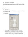
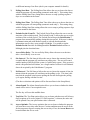
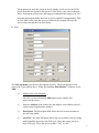
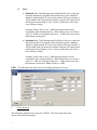
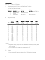
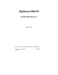
USER’S MANUAL MODEL 4001 PATH MONITOR SOFTWARE FOR WINDOWS 95, 98, ME, NT 4.0 AND 2000 SIGNALCRAFTERS TECH, INC. 57 Eagle Rock Avenue East Hanover, NJ 07936-3144 (800) 523-5815 or (973) 781-0880 www.signalcrafters.com i SIGNALCRAFTERS TECH, INC. MODEL 4001 PATH MONITOR FOR WINDOWS 95, 98, ME, NT 4.0 AND 2000 SOFTWARE 9/20/00 TABLE OF CONTENTS: Getting Started: I. Installing Software & Hardware Requirements 1 II. Main Menu a) File Menu b) Set Up Menu c) Report Menu d) Polling Menu e) Help Menu 1 1 1 1 1 1 Begin Programming: III. Set Up Menu A. Program sub-menu 1) Communications Ports 2) Polling Start Date 3) Polling Start Time 4) Exclude Period From / To 5) Access Relay Delay 6) Site Interval 7) Poll Interval 8) Alarm Sound 9) Test Print 10) Access Optimize B. Sites sub-menu 1) Adding Sites To Database 2) Address 3) Description 4) Auto Poll 5) Dial Number 6) Access 7) Sub Master 8) Access Reset 9) Frequency Tolerance ± 10) Inbound 11) Outbound 12) Noise ii 2 2 2 3 3 3 3 3 3 3 3 3 4 4 4 4 4 5 5 5 5 5 6 6 7 V. VI. VII. VIII. C. Users sub-menu 1) Adding Users To Database 2) Name 3) Privilege 4) Password 8 8 8 8 8 File Menu 9 A. History 1) Create 2) Load B. Exceptions 1) Create 2) Load C. Change User D. Exit E. Quit 9 9 9 9 9 9 10 10 10 Report Menu A. View Data 1) History 2) Exception B. Generate 10 10 Polling Menu 10 A) Single Mode B) Auto Mode C) Manual Mode 10 10 10 Application Note: Model 5493 DTMF to ASCII Modem Files to Backup or Transfer 11 12 10 iii Software Programming: Model 4001, Path Monitor for Windows Getting Started: I. INSTALLING SOFTWARE & HARDWARE REQUIREMENTS Insert disk 1 or CD-ROM and press Start, Run. Browse the floppy or CD-ROM for the setup.exe file or type x:\setup.exe and then press OK. P-75, 3 ½ Floppy, VGA Graphics Card, Printer, 32MB of RAM, 5MB of Hard Drive Space, 1 Serial Port, 1 Parallel Port, 101 Enhanced Keyboard, Mouse, CD-ROM and Windows 95, 98, NT 4.0 or 2000. II. MAIN MENU The Main Menu gives the user five menu choices; File, Set Up, Report, Polling and Help. a) The File Menu contains four sub-menus; History, Exceptions, Change Users, Printer Setup and Exit. b) The Set Up Menu contains four sub-menus; Sites, Users and Program. c) The Report Menu contains two sub-menus; View Data and Generate. d) The Polling Menu has four sub-menus; Single, Auto and Manual. e) The Help Menu has three sub-menus; Contents, Keyword Search and About. 1 III. ACCESSING THE HELP SCREENS Path Monitor has a help screen to assist the user at any time during the program. By pressing Help on the menu bar and selecting Keyword Search you can find the Help screen your looking for. Begin Programming: IV. SETUP MENU From the Main Menu select the Set Up Menu. Once the set up menu is displayed on the screen select the Program sub-menu. A. Program sub-menu: 1) Select one of four Com Ports that your Model 5493 is connected to on your computer. NOTE: Com Ports One and Three and Com Ports Two and Four share the same interrupts. If you are planning to use a Mouse or another Modem on your computer you will not be able to put the 5493 on the same interrupt line as the other equipment. That is if your mouse is on Com Port Three you will not be able to set up the 5493 on Com Port One. Reconfigure the Com Ports on your computer so that you can put your mouse and your 5493 DTMF to ASCII Modem 2 on different interrupt Com Ports (check your computer manual for details). 2) Polling Start Date. The Polling Start Date allows the user to choose the date at which the program will start polling (automatic mode only!). This setting along with the Polling Start Time setting allows the user to setup a polling sequence days or even months in the future. 3) Polling Start Time. The Polling Start Time allows the user to choose the time at which the program will start polling (automatic mode only!). This setting along with the Polling Start Date setting allows the user to setup a polling sequence days or even months in the future. 4) Exclude Period: From/To. The Exclude Period From allows the user to set the start time of the exclude period. The Exclude Period To allows the user to set the end time of the exclude period. The Exclude Period keeps the Path Monitor program from automatically polling during this time period. If the user is sharing a communication path with another system or with one that downloads information once per day, as an example: Midnight. You would set up the Exclude Period start time for Midnight and the Exclude Period end time to Midnight plus the download time. 5) Access Relay Delay. The Access Relay Delay allows the user to set the time after a Access Relay is set or reset. 6) Site Interval. The Site Interval allows the user to choose the amount of time (in seconds) that the program will wait between polling sites. The user will want a smaller number in this field if the system is a polled only system. If the system is mixed with polled and self-initiate, use a larger number to allow for self-initiated data to be acquired by the Path Monitor program. 7) Poll Interval. The Poll Interval allows the user to choose the amount of time (in minutes) that the program will wait between the polling cycles. This time is the time that the program waits between polling the last site and begins the polling cycle again, starting with the first site. (The above selections and options will be discussed later in the Setup Menu). 8) Alarm Sound. The Alarm Sound option allows you to choose whether the alarm sound will be active if an exception occurs. The Esc key will reset this audible alarm. 9) Test Print. The Test Print option allows you to choose whether tests will Always, On Exceptions or Never be printed. If “On Exceptions” is chosen, the entire test will be printed if any out specification value is detected. 10) Access Optimize. The Access optimizes the user to choose whether the program will reset the access relays after the test. Certain conditions must be met in order for the program to bypass resetting the access relays. First, the Access Reset must be turned on in the Access code. 3 The program also users this setting to decide whether it will un-seize the PSTN line, or keep the line seized for the next test. If the Dial # is the same as the next Dial #, the program will not issue the hang-up command if this setting is on “No”. Note that the program makes decisions on Access and PSTN independently. That is, if the Dial # is the same but Access is different, the program will reset the Access relays, but not the Line Seize Relay. B. Sites: The Sites sub-menu gives the user four options to select. These four options are the same as the Types options above. When first installing Path Monitor software, select ADD. 1) Adding Sites to the Database Once the user has selected the ADD option a new window will appear on the screen. 2) Enter the Address of the remote site (this address is the address selected on the remote Signalcrafters module). 3) Description. The Description field allows the user to enter the name of the site being added. 4) Auto Poll. The Auto Poll option allows the user to define if this site being added should be part of an Auto Poll cycle. Move the cursor part of an Auto Poll cycle. Move the cursor to either “YES” or “NO”. 4 5) Dial Number. The Dial Number input field allows the user to enter the phone number (up to 11 digits) that the master station will dial to reach the remote site. NOTE: Leave this field blank if this site is not accessed via a PSTN. 6) Access. The Access field allows the user to enter the access codes required to reach this site. In autodial applications, the program will attempt to dial the phone number first, then set the access relays. Here is an example of how to use the access relays: To set the first 4 relays on a Model 2452 (8x1 Relay Module) for a fourwire circuit the following access would be required: ABC1*1.ABC1*2.ABC1*3.ABC1*4. To set the second 4 relays for a second four-wire circuit the following access would be required: ABC1*5.ABC1*6.ABC1*7.ABC1*8. Note: At the end of each relay access number you must type a period at the end of each relay code (ABC1*1.). 7) Sub-Master. The Sub-Master choice box allows you to choose whether this site has a Sub-Master between it and the computer. Note: The Sub Master wake up command must be issued in the Access field. If Sub-Master address is 2590: 2590*D. 8) Access Reset. The Access Reset allows the user to choose whether the program will reset the access relays after the test. Certain conditions must be met in order for the program to bypass resetting the access relays. First, the Access Optimize must be turned on in the Program Menu. Second, the following site must have the same Access code. The program also uses this setting to decide whether it will un-seize the PSTN line or keep the line seized for the next test. If the Dial # is the same as the next Dial # then the program will not issue the hang-up command when this setting is on “No”. Note that the program makes decisions on Access and PSTN independently. That is if the Dial # is the same but Access is different then program will reset the Access relays but not the Line Seize Relay. 9) 5 Freq. Tol. The Frequency Tolerance Input field allows you to set the frequency tolerance of this site. If a test occurs outside of this specification then the test will be added to the exceptions file and the computer will sound an alarm when the Program Sound setting is “On”. 10) Inbound. a) Minimum field. The Minimum field allows the user to enter the minimum amount of loss (in dB) tolerable on the inbound path. If a test occurs outside of this specification the test will be added to the exceptions file and the computer will sound (when the Program Sound setting is “On”). Example: If this value is set to –14dB, the most amount of level acceptable on the inbound path is -14dB. If the test were to return a value of -13dB an exception would occur. b) Maximum field. . The Maximum field allows the user to enter the maximum amount of loss (in dB) tolerable on the inbound path. If a test occurs outside of this specification the test will be added to the exceptions file and the computer will sound (when the Program Sound setting is “On Example: If this value is set to –18dB the most amount of loss acceptable on the inbound path is -18dB. If the test were to return a value of -19dB an exception would occur. c) Reference field. The Reference field allows the user to enter the level in dB of the remote Model 5212 Loopback Receiver. 11) Outbound. a) Minimum field. The Minimum field allows the user to enter the minimum amount of loss (in dB) tolerable on the outbound path. If a test occurs outside of this specification, the test will be added to the exceptions file and the computer will sound (when the Program Sound setting is “On”). Example: If this value is set to –14dB, the least amount of loss acceptable on the inbound path is -14dB. If the test were to return a value of -13dB, an exception would occur. b) Maximum field. . The Maximum field allows the user to enter the maximum amount of loss (in dB) tolerable on the outbound path. If a test occurs outside of this specification, the test will be added to the exceptions file and the computer will sound (when the Program Sound setting is “On”). Example: If this value is set to –18dB, the most amount of loss acceptable on the inbound path is -18dB. If the test were to return a value of -19dB, an exception would occur. d) The cursor will be at the Reference field. The Reference field allows the user to enter the level in dB of the remote Model 5212 Loopback Receiver. 6 12) Noise. a) Minimum field. The Minimum input field allows the user to enter the minimum amount of acceptable loop-backed noise on the combined inbound / outbound path. If a test occurs outside of this specification, it will be added to the exceptions file and the computer will sound (when the Program Sound setting is “On”). Noise is an absolute value, there is no reference setting. Example: If this value is set to –30dB, the least amount of noise acceptable on the combined paths is –30dB. If the test were to return a value of –29 dB, an exception would occur. –36 dB is the lowest value the hardware can measure. b) Maximum field. The Maximum input field allows the user to enter the maximum amount of acceptable loop-backed noise on the combined inbound / outbound path. If a test occurs outside of this specification, it will be added to the exceptions file and the computer will sound (when the Program Sound setting is “On”). Noise is an absolute value, there is no reference setting. Example: If this value is set to –20dB, the most amount of noise acceptable on the combined paths is –20dB. If the test were to return a value of –21 dB, an exception would occur. –36dB is the lowest value the hardware can measure. Note: Set this to –36dB. EDIT - The Edit sub-menu allows the user to change parameters of a site. C. Users sub-menu The last Option under the Set Up menu is USERS. The Users menu allows the user to select from four options. 7 ADD - The Add sub-menu allows the user to add a new user to the system. Once a User’s Name has been added, the Name/Password window will appear upon start up of Path Monitor. EDIT - The Edit sub-menu allows the user to change parameters of a user. 1) Adding Users To the Database When initializing the system, choose the option ADD. Once the ADD option has been selected a window will appear on the screen with the cursor in the Name field. 2) The Name field should be filled in with a users name. NOTE: Signalcrafters recommends that a Manager Level user be entered in as the first user (Manager \ Operator Privilege discussed below). 3) The cursor will now prompt you to select the Privilege option. There are two levels of security, Operator and Manager. Managers can access all windows of the Path Monitor software. Operators cannot access History, and DOS Shell in the File Menu, and the entire Set Up menu. NOTE: Both the password and name must match with the user-entered strings or the Operators privilege will be assumed. Select the Privilege and press “enter”. 4) The cursor will now prompt the user for the Password. The Password entry allows the user to associate a users name and password with a privilege. Two security levels of access are available – Manager and Operator. Managers can access all 8 windows in Path Monitor software. Operators cannot access the Setup menu. The Setup menu is now complete. V. FILE MENU: There are other menu selections in the Main Menu and we will discuss those now. A. History - The History option allows the user to: create a new file, open an existing file, or erase a History file. The Path Monitor requires the user to have a History file for storage of data. Select the History option and press “open”. 1) The first step is to make a New History File. Enter the name of the History File that you want the data stored. Example: JAN00.his The File extension .his will automatically be added to the File name. Once the file name has been entered press “enter”. 2) To change History files, from the Main Menu, select the File sub-menu, select History . When the History sub-menu is brought up on the screen select Open. This option allows the user to select which History File the Data is collected in. You may have many different History files to select from. Select one and press “open”. B. Exceptions: The Exceptions option allows the user to: create a new, open an existing, or erase an Exceptions file. The Path Monitor requires the user to have an Exceptions file for storage of data. Select the Exceptions option and press “open”. 1) The first step is to make a New Exceptions File. Select and press “open”. Enter the name of the Exceptions File that you want the data stored. Example: JAN00.exc The File extension .exc will automatically be added to the File name. Once the file name has been entered press “open”. 2) To change Exceptions files, from the Main Menu, select the File sub-menu, select Exceptions and press “enter”. When the Exceptions sub-menu is brought up on the screen select Open. This option allows the user to select which Exceptions File the 9 Data is collected in. You may have many different Exceptions files to select from. Select one and press “open”. C. Change User: The Change User allows different users to access the system without having to exit the Path Monitor program. D. Printer Setup: The Printer Setup allows you to select different printers or settings. Printer Setup controls the output for the Report. E. Exit: This option allows the user to exit the Path Monitor program. There are two other Menu Options on the Main Menu which we have not talked about. VI. REPORT MENU: View Data: The View selection allows you to browse through the history and exception files. 1. History: The History selection allows you to browse through the active history file. 2. Exception: The Exception selection allows you to browse through the active exception file. Generate: The Generate window allows you to Graph a history file entry. View Sites: The View Sites will display all sites that were entered in to the database. VII. POLLING MENU: The last menu selection is the Polling option. The Polling Option opens a sub-menu with four options; Single, Auto, Manual and Monitor. A) Single - The single option allows the user to poll just one selected site. After choosing the Single Mode, a site list will come on the screen. Select the appropriate site and press “enter”. The Path Monitor program will automatically dial (if set up for PSTN), access, poll and reset the access relays. All data will be displayed on the screen in the Single Mode. If you have chosen the option for the printer, the program will print to the printer. B) Auto - The Auto mode allows the user to poll ALL sites that have been chosen for automatic polling. The program automatically accesses, polls and resets the access parameters. The Data will be displayed and printed according to the options which were discussed in the Program menu. C) Manual - The Manual poll mode allows the users to generate any 1-7 character DTMF code. Any six digit code ending on 03 will cause the Model 5493 to go into measurement mode. Any six digit code ending in 0B will cause the Model 5493 to go into a Stepped Sweep Mode. 10 Application Note: Model 5493 - DTMF to ASCII Modem I. Setting up your Model 5493 for use with Path Monitor software. A) Front Panel Dipswitch Settings: Dipswitch 1 2 3 4 II. Function Echo ASCII input Keyboard input Unused Radio/PSTN To Left To Right Echo after each DTMF out Store and Forward K1 for PTT K1 for Line Seize Program Wire Setup Pin BROWN Baud Rate RED Interdigit Timer (seconds) ORANGE K1 Key-Up Delay (seconds) YELLOW DTMF ON (ms) GREEN DTMF OFF (ms) BLUE Reset Timer (seconds) D 1 2 3 4 5 6 7 8 9 0 * # A B C 75 150 300 600 1200 2400 4800 9600 75 150 300 600 1200 2400 4800 9600 1.6 0.1 0.2 0.3 0.4 0.5 0.6 0.7 0.8 0.9 1.0 1.1 1.2 1.3 1.4 1.5 0.0 0.1 0.2 0.3 0.4 0.5 0.6 0.7 0.8 0.9 1.0 1.1 1.2 1.3 1.4 1.5 80 05 10 15 20 25 30 35 40 45 50 55 60 65 70 75 80 05 10 15 20 25 30 35 40 45 50 55 60 65 70 75 0.0 0.5 1.0 1.5 2.0 2.5 3.0 3.5 4.0 4.5 5.0 5.5 6.0 6.5 7.0 7.5 * Notes: 1) Program the orange “program wire” on 5493 Module to desired key-up delay (Refer to 5493 Manual). 2) K1 is not operated if the orange wire is programmed to “D”. III. Voltage 1) Prior to making DC connections, please refer to 5493 Manual and drawings. 11 Signalcrafters Protocol: 6 Data bytes (8 data bits, 1 start, 1 stop). Model 5212 and 2212. 1 2 3 4 Module Address 5 6 Function Common Commands: Remote Module Address = 1590. 159001: Loopback mode. 159002: DTMF identification. 159003: Generate a tone sequence from 404Hz to 2804Hz @ 0dB (Inbound test). 159004: Generate 1004Hz @ 0dB. 159005: Generate 1004Hz @ -13dB. 159006: Amputate remote. 159007: Quiet Termination (For noise measurements). 159008: Generate a tone sequence from 404Hz to 2804Hz @ -13dB(Inbound test). 159009: Generate 2804Hz @ 0dB. 159000: Reset Remote. 15900B: Generate a tone sequence from 404Hz to 2804Hz @ 0dB (Outbound test). Set relay 1 of relay card 1 (Model 2452, 5452): ABC1*1 Reset relay 1 of relay card 1 (Model 2452, 5452): ABC1#1 Pickup phone with Model 5493: ABC1A1 Hang-up phone with Model 5493: ABC1#1 Files to Backup or Transfer There are files that you will need to backup. These same files can transfer to a new computer or when you upgrade to a new version (the old data files will get erased so you will need to backup these files). The default directory is: C:\Program Files\Signalcrafters\Path Monitor Files to Backup: history.db savelast.DB sites.db users.db You may want to also backup the history files and the exception files. Files to Backup: *.his *.exc 12