1
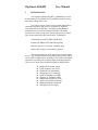
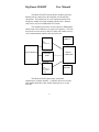
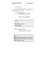
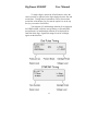
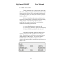
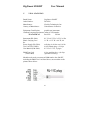
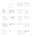
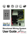
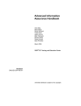
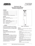
DigiSmart 4300-RT USERMANUAL Version 1.03 (tm) DigiSmart is a trademark of Nicollet Technologies, Inc. Copyright (c) 2004, NTI 3/04 DRN 3407 DigiSmart 4300-RT User Manual Table of Contents I. INTRODUCTION II. GENERAL OPERATION A. Test Access B. Display Configuration C. Button Functions D. Timing Analysis E. Hook / Scan / Clear F. Open Termination 7 8 8 13 15 16 TEST PROCEDURES A. Monitoring Digits B. Dialing Digits C. DID/PBX Simulation D. DID/CO Simulation E. E&M Terminate F. E&M Originate G. DID Bridge Mode H. Receiving Tones 17 17 20 21 22 23 24 25 IV. WARRANTY & REPAIR 26 V. 27 VITAL STATISTICS III. APPENDIX: Specifications 2 3 28 DigiSmart 4300-RT I. User Manual INTRODUCTION The DigiSmart Model 4300-RT is a handheld test set for troubleshooting 2-wire E&M, POTS and DID circuits, as well as measuring Voltage and Levels. Ten years of service in telcos across North America have earned the DigiSmart 4000-series a reputation for simplicity, versa-tility and solid reliability. This family of handheld test instruments now welcomes the Model 4300-RT, which adds powerful new features to the suite of functions previously found only on the popular 4200-RT from Nicollet Technologies: Transmit/Receive MF, DTMF and DP digits Emulate 2W E&M, POTS and DID signaling Measure Signal Level of tones, including digits Display DC voltage level and battery polarity This new DigiSmart is much more than just a digit display device. The 4300-RT handles the signaling required to test either end of a DID or E&M circuit, including E-911 trunks at the PSAP. Or monitor any analog line to display digits and timing intervals. Here are a few of the other features that make it indispensable: Bridge and Terminate modes Fixed-frequency tone source Wink intervals and duration Timing analysis of each digit Wink or Immediate-start DID Originate or Terminate E&M Bantam and modular test jacks Speaker for audible monitoring 600Ω/900Ω/Open termination Wall plug-in power supply 3 DigiSmart 4300-RT User Manual The Model 4300-RT includes both a modular jack and a bantam jack for connection to the telephone circuit and other equip-ment. The bantam jack is a two-conductor interface that accepts the standard test cord included with the 4300. Bantam cords can be used to test DID and POTS circuits. The modular jack must be used to connect to E&M trunks, which require four conductors (see page 26 for pinouts). This jack may also be used to connect a butt set, which will enable two-way voice communication with the other end of the line. RECEIVE DISPLAY MF DTMF DIAL PULSE LINE INTERFACE BATTERY FEED MICRO COMPUTER TRANSMIT MF DTMF DIAL PULSE CALL PROG 1004 Hz KEYPAD The Model 4300-RT shares many operational characteristics with the 4200-RT. Craftsmen who have used the older model should have little trouble learning how to use the 4300-RT. 4 DigiSmart 4300-RT User Manual Power to the unit is supplied by a dual-output, wall-mount transformer. To use the 4300, plug the transformer into a standard, 3-prong electrical outlet (115 VAC, 60 Hz) and connect the power cord to the jack on the left side of the unit. The Power/Volume control is on the right side of the unit. Rotate this switch until it clicks ON. Speaker volume can then be adjusted by rotating the control down or up until the desired amplitude is reached. The model and version number will appear briefly on the top line of the display, followed by the signal level (dBm) and voltage measurement (DCV) on the third line. The bottom line will contain the three status words shown in the figure below: The unit is now set to send/receive DTMF digits, is ONhook and is ready to operate in a NORMAL loop environment. This power-up default mode allows you to bridge a telephone line and display DTMF digits. If you wish to display Dial Pulse or MF digits instead, simply use the DIAL MODE button as described on page 9. 5 DigiSmart 4300-RT User Manual 6 DigiSmart 4300-RT II. User Manual GENERAL OPERATION A. Test Access The telephone circuit may be accessed by using the cable supplied with the 4300. The bantam plug at one end of this cable fits into the jack on the top of the unit. The other end features a pair of 5-way test clips which connect to tip and ring at the demarc point. A modular cord can be used instead of this "bantam" test cord. An RJ-11C jack is located on the top of the unit next to the bantam jack. The inner pair of this jack provides a two-wire connection to the telephone circuit being tested. When testing 2W E&M trunks, four conductors of the modular jack are used. A pinout diagram is shown at the bottom of page 26. The 4300 can monitor DID, E&M or other types of analog telephone circuits through a high-impedance connection. Twoway traffic can be monitored and digits displayed while calls are in progress, without interfering with signaling between the central office and the customer premise. The 4300 supports two such monitor modes. The default on power-up is NORMAL mode (On-Hook), which will display digits that pass back and forth across the circuit. The other mode is called DID-BRidge, in which both digits and timing intervals are captured and displayed for wink-start DID trunks. In the active modes, the 4300 acts as one end of a trunk to simulate the operation of switching equipment. The 4300 performs loop seizure, wink recognition and digit feed when it originates calls. When it terminates a call, it will perform winkback, digit capture and battery reversal. Battery is supplied as required by the protocol. 7 DigiSmart 4300-RT User Manual B. Display Configuration The front panel of the 4300 contains a 4-line by 16character Liquid Crystal Display (LCD), which will hold up to 32 digits on the first two lines. Both received and transmitted digits are displayed. NOTE: Special MF tones are displayed as two characters (see page 12), thus reducing display capacity to less than 32 digits. The third line of the LCD is reserved for signal level, voltage measurement and status indicator. The current dialing and signaling modes are displayed on the bottom line. C. Button Functions Below the LCD is a 4x4 keypad and six black buttons. The keypad contains the ten numeric digits 0 through 9 and the DTMF *, #, A, B, C and D. Smaller type above these six DTMF characters identifies the MF tones that are produced when these keys are pressed in the MF Dial Mode. The functions of the six black buttons are described on the following pages. 8 DigiSmart 4300-RT User Manual DIAL MODE Selects what types of digits will be transmitted and received by the 4300-RT: DTMF, Dial Pulse, MF, also prepares the unit to transmit Call Progress tones, measure single-frequency tones, or set the idle-loop voltage threshold. The current Dial Mode is shown in the bottom left corner of the display. Default mode: display reads "DTMF" The unit is ready to send or receive DTMF digits 0-9, *, #, A, B, C, D. Depression 1: display reads "PULSE" The unit is ready to send or receive Dial Pulse digits 0 through 9. Depression 2: display reads "MF" The unit is ready to send or receive MF digits 0-9, KP, ST, STP, ST2P, ST3P and Pause. Depression 3: display reads "CALL" The unit is ready to transmit Call Progress sequences. See page 29 for specifications. Depression 4: display reads "TONE" The unit is ready to accurately measure the dB level of single-frequency tones such as those commonly used for testing telephone circuits. Depression 5: "Press CLEAR to set hook Threshold or MODE to exit" Sets the idle-loop voltage threshold for monitoring Line status and Dial Pulse digits. When working on a circuit that does not use 48VDC (e.g., a 24-volt system), press the CLEAR button when the line is idle to set the new voltage threshold. Then press the DIAL MODE button until the proper mode is displayed. 9 DigiSmart 4300-RT User Manual FUNC tion Selects one of eight Supervision modes. The current mode is shown in the lower right corner of the display. Default mode: display reads "NORMAL" The unit is set up to monitor or terminate a standard analog circuit (POTS). Depression 1: display reads "PBX-WS" The unit is set up to operate as the Customer Premise (PBX) side of a Wink-start DID trunk. Depression 2: display reads "PBX-IM" The unit is set up to operate as the Customer Premise (PBX) side of an Immediate-start DID trunk. Depression 3: display reads "CO-WS" The unit is set up to operate as the Central Office side of a Wink-start DID trunk (DOD). Depression 4: display reads "CO-IM" The unit is set up to operate as the Central Office side of an Immediate-start DID trunk (DOD). Depression 5: display reads "EMT-WS" The unit is set up to operate as the Terminate end of a 2-wire E&M trunk (Wink start, Type I). Depression 6: display reads "EMO-WS" The unit is set up to operate as the Originate end of a 2-wire E&M trunk (Wink start, Type I). Depression 7: display reads "DID-BR" The unit is set up to Bridge (monitor) a DID trunk. 10 DigiSmart 4300-RT User Manual CLEAR Clears digits from the top two lines of the display. Should be pressed prior to sending or receiving the next dialing sequence. Prepares the unit for the next call. SCAN/1004Hz Moves the cursor from left to right to analyze individual digits that have been received. Also displays the Wink timing intervals (Pre-Wink, Post-Wink, Wink duration). If held down for two seconds, activates the 1004 Hz tone source. After the SCAN button is pressed to analyze digits or wink timing, you must press CLEAR to prepare for the next call. TERM ination Selects 600Ω or 900Ω impedance, or Open termination (see page 16). Has no effect in the monitor modes, since these are high-impedance connections. TERM is a threeposition rocker switch. HOOK Selects the On-Hook or Off-Hook condition for POTS and E&M lines. Controls Loop Seizure (DID/CO calls) and Reverse Battery (used to answer DID/PBX calls). 11 DigiSmart 4300-RT User Manual KEYPAD Dialing sequences are entered via the 4x4 keypad. The following digits are available in each Mode: Dial Pulse: 0 through 9 DTMF: 0-9, *, #, A, B, C, D Multi-Frequency (MF) coded as follows: 0-9 KP ST STP ST2P ST3P Pause (numeric keys) (* key; displayed as KP) (# key; displayed as ST) (A key; displayed as S1) (B key; displayed as S2) (C key; displayed as S3) (D key; displayed as P) Call Progress tones coded as follows: 1 == Dial Tone 2 == Reorder 3 == Busy 4 == Ringback 5 == Recall Dial 6 == Special Audible Ring 7 == Intercept 8 == Call Waiting 9 == Busy Verification 0 == Executive Override * == Confirmation 12 DigiSmart 4300-RT User Manual D. Timing Analysis To analyze Wink timing parameters, press the SCAN button after sending or receiving a Wink. The 4300 will display the following values in milliseconds: CO-WS and EMO-WS modes "Pre-Wink" interval -- delay between loop closure and wink from PBX "Wink" duration -- length of Reverse Battery received from the PBX PBX-WS and EMT-WS modes "Post-Wink" interval -- delay between wink and first digit received from CO 13 DigiSmart 4300-RT User Manual To analyze digits, operate the SCAN button to move the cursor from left to right across the digits displayed on the first and second lines. Timing analysis parameters will be shown on the second line of the display (as you scan the top line) or on the top line (as you scan the second line). Tone duration (T) and Interdigit duration (I) are displayed for DTMF and MF, while the average Pulses per Second (PPS), percent Break (%) and Interdigit duration (I) are displayed for each Dial Pulse digit. Signal and voltage levels for each digit appear on the third line. 14 DigiSmart 4300-RT User Manual E. Hook / Scan / Clear Timing parameters can be analyzed any time after they occur, just by pressing the SCAN button as described in the previous section. After viewing the wink intervals or scanning the digits, you must press CLEAR to prepare for the next call. We have found that when using our 4000-series test sets it is good practice to release the call before doing timing analysis. The following sequence of steps, performed after each call is answered, will eliminate confusion when doing repeated tests: (1) press HOOK button to release the call (2) press SCAN to analyze digits and wink timing (3) press CLEAR to prepare for the next call It should be noted that signal and voltage levels are also recorded for each digit that is received by the 4300. When digits are scanned, these parameters appear on the third line of the display. The words OVER or UNDER will be used in place of a numeric value whenever the measurement is outside the ranges shown on pages 29-30. 15 DigiSmart 4300-RT User Manual F. Open Termination When the TERM switch is in the center (OPEN) position, all tone dialing functions are disabled and termination resistance is removed. This mode allows a signal analyzer to be connected to the circuit, through the 4300, for more extensive testing of noise level and frequency response. (dB measurements assume 600Ω termination.) The 4300 will perform all the signaling required to establish an audio path across an E&M, POTS or DID circuit. A pass-through connection to the circuit will then be established, as shown in the figure below. A loss of approximately 0.5 dB can be expected in this setup, which avoids double termination of the line. 16 DigiSmart 4300-RT III. User Manual TEST PROCEDURES A. Monitoring Digits The 4300 defaults to the monitor mode when the Power/ Volume switch is first turned on. In this mode, the unit monitors DTMF digits across a high-impedance connection to Tip and Ring. If you are monitoring a wink-start DID trunk, use the DID-BRidge mode as described on page 24. To properly display Dial Pulse or MF digits, press the DIAL MODE button once or twice. If a problem with Dial Pulse digits is encountered, it may be necessary to set the voltage threshold. This is done by pressing the DIAL MODE button until Hook Threshold appears. Then press the CLEAR button when the line is idle. B. Dialing Digits Step 1: Turn on the unit by operating the Power/Volume switch on the right side. The default setting (DTMF) will appear at the bottom of the display. Step 2: Press the DIAL MODE button to select Dial Pulse or MF, as described on page 9. Step 3: Select the proper line impedance (600Ω or 900Ω) by toggling the TERM switch. Note: OPEN termination disables all tone dialing. (Continue with either the Manual Dial or Store & Forward steps on the next page.) 17 DigiSmart 4300-RT User Manual MANUAL DIAL Step 4: Go off-hook by pressing the HOOK button. The word "OFF" will appear in the middle of the last line of the display. Step 5: Enter the desired digit sequence on the keypad. Digits will be displayed and then transmitted in the selected dialing mode. Note: Step 6: The dialing mode may be changed during a dialing sequence by operating the DIAL MODE button as part of the sequence. So you may change from DTMF to Dial Pulse to MF in any combination during a dialing sequence. Go On-Hook when desired by momentarily pressing the HOOK button. The word "ON" will then be displayed in the middle of the last line. STORE & FORWARD Step 4: Enter the desired digit sequence on the keypad before going Off-Hook. Step 5: Go Off-Hook by pressing the HOOK button once. Note: Two seconds after the unit is placed in an OffHook state, the digit sequence entered in Step 4 above will be transmitted at the standard dialing rates (see pages 28-29). 18 DigiSmart 4300-RT User Manual LAST NUMBER REDIAL After entering the digits as described above under Manual Dial or Store & Forward, do the following: Step 1: Go on-hook by pressing the HOOK button and wait a moment for the central office to clear. Step 2: Go off-hook by pressing the HOOK button again. The digit sequence will be redialed. Press CLEAR prior to entering a new digit sequence. PAUSE DURING MF DIALING At times it may be necessary to transmit more than one digit string (e.g., DNIS + ANI) from the 4300-RT. While MF digits are usually framed with the KP and ST tones, some receiving equipment requires a short delay to prepare for the second set of digits. In these cases, use the D key in the lower right corner of the keypad to insert a Pause between the digit strings. Each Pause represents a 250 msec delay and is shown by a P on the display. C. DID / PBX Simulation 19 DigiSmart 4300-RT User Manual Step 1: Turn the unit on. Step 2: Select the proper line impedance by toggling the TERM switch. Step 3: Select PBX-WS or PBX-IM trunk supervision by pressing the FUNC button. Step 4: Select DTMF, Dial Pulse or MF by pressing the DIAL MODE button. Step 5: When the unit detects loop closure from the CO, it will wink back only if PBX-WS was selected in Step 3. (See DID Parameters on page 30.) Step 6: Digits received from the CO will be displayed. Step 7: To accept the call, press the HOOK button. The words "REVERSE BATTERY" will appear on the third line of the display. Step 8: Press the SCAN button to view the Post-Wink interval and digit timing parameters. Step 9: To release the call, press CLEAR: a)If the trunk is still seized, you must wait until the trunk is released and then press CLEAR again to go on hook. b) If the CO has already released the trunk, press the HOOK button to return to the idle loop condition. If desired, you may transmit 1004Hz, DTMF, MF of Call Progress tone in this function, however the 4300-Rt must be Off-Hook or in the answered (reverse battery) condition. 20 DigiSmart 4300-RT User Manual D. DID / CO Simulation Step 1: Turn the unit on. Step 2: Select the proper line impedance by toggling the TERM switch. (Note: OPEN position disables tone dialing in Step 8.) Step 3: Select CO-WS or CO-IM trunk supervision by pressing the FUNC button. Step 4: Select DTMF, Dial Pulse or MF by pressing the DIAL MODE button. Step 5: Enter the desired digit sequence on the keypad. The digits will be displayed on the top line. Step 6: Close the loop by pressing the HOOK button once. The word "OFF" will appear on the last line of the display. Step 7: The PBX will sense loop closure and will return a Wink if it is so configured. In this case, the word "WINK" will appear on the display. Step 8: The 4300 will transmit the digit sequence that was entered in Step 5. The PBX will accept the call (by reversing battery) if the digits are found to be valid. Step 9: Open the loop by pressing the HOOK button after the call is complete. Press SCAN to view the Pre-Wink interval and Wink duration. Press CLEAR to prepare for the next call. 21 DigiSmart 4300-RT User Manual E. E&M Terminate Mode Step 1: Turn the unit on. Step 2: Select the proper line impedance by toggling the TERM switch. Step 3: Select EMT-WS by pressing the FUNC button five times. Step 4: Select DTMF, Dial Pulse or MF by pressing the DIAL MODE button. Step 5: After detecting seizure, the 4300 will wait 100 msec before sending a 200-msec Wink signal. Step 6: Digits transmitted by the remote equipment will appear on the display. If the line is dropped, the word "DISCONNECTED" will appear. Step 7: Press the HOOK button to accept the call. The word "ANSWERED" will be displayed. Step 8: Press HOOK to release the call. Press SCAN to view the Post-Wink interval. Press CLEAR to prepare for the next call. 22 DigiSmart 4300-RT User Manual F. E&M Originate Mode Step 1: Turn the unit on. Step 2: Select the proper line impedance by toggling the TERM switch. (Note: OPEN position disables tone dialing in Step 8.) Step 3: Select EMO-WS by pressing the FUNC button six times. Step 4: Select DTMF or MF dialing mode by pressing the DIAL MODE button. Pulse dialing is not available in E&M Originate mode. Step 5: Enter the desired digit sequence on the keypad. If the line is off-hook, the word "BUSY" will appear on the third line of the display. Step 6: Seize the trunk by pressing the HOOK button once. The word "OFF" will appear on the last line of the display. Step 7: The remote equipment will return a Wink signal and the word "WINK" will appear on the display. Step 8: The 4300 will then transmit the digit sequence. If the remote equipment accepts the call, the word "ANSWERED" will be displayed. Step 9: Press HOOK to release the call. Press SCAN to view the Pre-Wink interval and Wink duration. Press CLEAR to prepare for the next call. 23 DigiSmart 4300-RT User Manual G. DID Bridge Mode Step 1: Turn the unit on. Step 2: For accurate dB measurements, select the proper line impedance by toggling the TERM switch. Step 3: Select DID-BR by pressing the FUNC button seven times. Step 4: Select DTMF, Dial Pulse or MF by pressing the DIAL MODE button. Step 5: If the voltage level is less than 40VDC, the line may be busy. If the line is idle, reset the voltage threshold using DIAL MODE button (page 9). Step 6: Digits and signaling will be analyzed by the 4300 as they occur across the DID circuit. Step 7: Press the SCAN button to view the Wink timing intervals (see figure below). Step 8: Press SCAN again to analyze each digit. Press CLEAR to prepare for the next call. 24 DigiSmart 4300-RT User Manual H. Receiving Tones Step 1: Turn the unit on. Step 2: For accurate dB measurements, select the proper line impedance by toggling the TERM switch. Step 3: Select TONE by pressing the DIAL MODE button Step 4: Go Off-Hook by depressing the HOOK button The unit is ready to receive tones. The 4300-RT will not display the frequency, but will display the dB level as the tone is received. You also can hear the tone by adjusting the volume. 25 DigiSmart 4300-RT IV. User Manual WARRANTY AND REPAIR All DigiSmart products are warranted to be free from defects in materials and workmanship for a period of one year from date of purchase. Nicollet Technologies will, at its option, repair or replace any unit that is found to be defective during this period free of charge. Should the unit fail to operate properly at any time, please contact the manufacturer for repair service. Do not attempt to repair the DigiSmart yourself. To obtain a Returned Material Authorization (RMA) number, please call or write: Nicollet Technologies, Inc. 7901 12th Avenue South Bloomington, MN 55425 Tel: (954) 854-3336 Fax: (954) 854-5774 The DigiSmart Model 4300-RT will require calibration by factory-trained technicians every two to three years of normal use. This service restores the accuracy of the signal level and voltage measurements, and is performed at a nominal charge. The display window is clear plastic and may be cleaned with a soft cloth. Avoid using glass cleaner or other solvents, since this may fog the plastic. If the window becomes soiled, dampen the cloth with a mild soap solution and rub gently. Then wipe clean with a cloth moistened with warm water. Never immerse the unit in water, since this will damage the components inside. As with any piece of electronic equipment, protect your DigiSmart from static, freezing temperatures and excessive heat. 26 DigiSmart 4300-RT V. User Manual VITAL STATISTICS Brand Name: Order Number: DigiSmart 4300-RT DS-4300 Manufacturer: Country of Manufacture: Nicollet Technologies, Inc. United States of America Equipment Classification: portable test instrument Common Language Equipment Coding (CLEI) number: TEASAAJWAA Bar code: 220360 Instrument (DS-4300): Plastic Carrying Case: lbs. Power Supply (PS-4X00): Test Cord (TR-CORD): User Manual (UM-4300): 8.1" H x 4.2" W x 2.9" D, 2.0 lbs. 11" H x 13.5" W x 4.4" D, 4.0 wall plug-in, 8-foot cord, 1.4 lbs. 6 feet, bantam plug + (2) clips 8.5" H x 5.5" W, 32 pages E&M Test Cord: (EM-CORD) 6 feet, modular plug + (4) clips (optional accessory) Modular cords used to connect an E&M trunk to the 4300-RT, including the E&M Test Cord listed above, must conform to the pinouts shown below: 27 DigiSmart 4300-RT User Manual APPENDIX Specifications for the DigiSmart 4300-RT 28