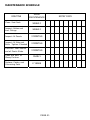
1
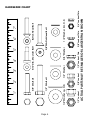
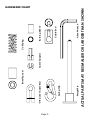
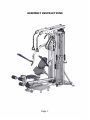
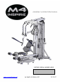
ASSEMBLY & OPERATION MANUAL
RECORD SERIAL NUMBER HERE
www.inspirefitness.net
by Health In Motion LLC
10-31-07
CONGRATULATIONS… You’ve just taken the first step to a healthier
and stronger body. This home gym by Inspire Fitness offers the key to
unlocking your body’s potential. Regular strength training on a home gym
has been shown to deliver a host of benefits including: increased muscle
tone, decreased body fat, improved energy levels, a reduction in stress, and
improved cardiac output. Once again, congratulations, you are on your way
to improving your self image, overall health and quality of life.
BEFORE ASSEMBLING YOUR HOME GYM
CAUTION:Two people are required to complete steps 1-6 to ensure that
the frame does not fall resulting in injury to the person assembling the
gym.
IMPORTANT: Read this entire manual before attempting to build or use
this machine. This manual contains step by step instructions for proper
assembly.
Use the parts list included in this manual to verify that all parts are
accounted for before assembly. If any parts are missing, contact the retailer
of this home gym for replacement parts. Or, call Inspire Fitness
at 714-738-1729
Make sure that adequate room has been cleared before attempting to build
your home gym. A rubber mat is recommended for use under your home
gym to protect wood flooring or carpeting from damage during assembly
and usage.
This home gym is intended for indoor use only. In addition, garages and
screened in porches are not recommended due to high humidity or dust.
Certain parts including guide rods can form rust in a humid environment,
resulting in impaired function.
Service of your home gym should only be preformed by an authorized
Inspire Fitness retailer. Service preformed by anyone else can result in loss
of warranty. If you need help finding an authorized retailer, please contact
us directly:
Inspire Fitness
637 S. State College Blvd.
Fullerton, CA 92831
Ph: 714-738-1729
Fx: 714-738-1728
www.inspirefitness.net
TABLE OF CONTENTS
Section Description…………………………………………………….
Page
Important Safety Instructions……………………………………….
1
Tools Required…………………………………………………………………
1
Parts & Hardware List…………………………………………………….
2
Hardware Chart ……………………………………………………………..
4
Cable Chart …………………………………………………………………….
6
Assembly Instructions…………………………………………………….
7
Decal Reference………………………………………………………………
36
Decal Placement………………………………………………………………
38
Accessories………………………………………………………………………
39
General Maintenance Information…….……………………………
40
Maintenance Schedule…….………………………………………………
41
Limited Warranty……………………………………………………………..
42
IMPORTANT SAFETY INSTRUCTIONS
Please read this entire manual and familiarize yourself with all decals and
warnings before using this home gym.
• WARNING! It is necessary to inspect this home gym regularly to
maintain safety and proper function. Please use the maintenance schedule
included towards the back of this manual. Immediately replace any and all
defective or worn parts. Pay special attention to moving parts such as the
cables and pulleys and connections to accessories. See General
Maintenance section for complete details.
• Use this home gym for its intended purpose as described in this Operation
Manual or the exercise chart. Do not use attachments not recommended by
the manufacturer.
• Do not hang from press arm. The press arm is not designed to
support human weight.
• Make sure bystanders are at least 5 feet away from the home gym while
it is in use.
• Keep children off the home gym at all times.
• Keep the home gym away from walls and clear of any obstructions and
furniture.
• Stop immediately if you experience shortness of breath, pain, or dizziness
during your workout. Inspire Fitness strongly recommends consulting your
doctor before starting an exercise program.
TOOLS REQUIRED FOR ASSEMBLY
•
•
•
•
•
•
•
•
Standard socket set (including 1/2”, 9/16” & 3/4" sockets)
1/2” wrench
9/16” wrench
3/4" wrench
Tape Measure
Rubber Mallet
Adjustable wrench
5 & 6mm Allen wrench – supplied
PAGE 1
PARTS & HARDWARE LIST
Item
1
2
3
4
5
6
7
8
9
10
11
12
13
14
15
16
17
18
19
20
21
22
23
24
25
26
27
28
29
Parts Description
Main Base
Rear Base
Main Upright
Brace
Lower Cable Column Mount
Lower Guide Rod Mount
Cable Column
Slider Assy, Cable Column
Top Beam Track
Upper Mount, Cable Column
Shroud Mount Assy, Wt. Stack
Support Beam, Wt. Stack
Top Beam Tube, Left
Top Beam Tube, Right
Top Beam Plate, Left
Top Beam Plate, Right
Track Index Arm, Left
Track Index Arm, Right
Guide Rod Spacer Plate
Guide Rod
Pulley Yoke, Weight Stack
Press Arm Mount, Left
Press Arm Mount, Right
Press Arm Assy, Left
Press Arm Assy, Right
Seat Frame
Back Pad Link
Back Pad Mount
Back Pad Tilt Selector Assy
Qty
1
1
1
1
1
1
1
1
1
1
1
1
1
1
1
1
1
1
1
2
1
1
1
1
1
1
1
1
1
Qty Rec'd
Item
30
31
32
33
34
35
36
37
38
39
40
41
42
43
44
45
46
47
48
49
50
51
52
53
54
55
56
57
58
PAGE 2
Hardware Description
Seat Mount Assy
Foot Platform Assy
Leg Extension Arm, Left
Leg Extension Arm, Right
Floating Pulley Bracket
Floating Pulley Bracket Assy
Dual Floating Pulley Assy
Dual Floating Pulley Assy,Twisted
Shroud Plate
Thigh Pad
Lumbar Pad
Seat Base
Weight Pin
Aluminum Endcaps
Rubber Donut
Foam Roller Assy
Top Weight / Selector Stem
Upper Cable
Press Arm Cable, Left
Press Arm Cable, Right
Cable Column Cable
Leg Extension Cable
Weight Stack Number
D Handle / Ab Strap
D Handle / Lat Strap
Ankle Strap
3 1/2" Pulley
4 1/2" Pulley
Pulley Cover
Qty
1
2
1
1
1
1
2
2
2
1
1
2
1
4
2
4
1
1
1
1
1
2
1
2
2
1
5
6
2
Qty Rec'd
PARTS & HARDWARE LIST
Item
1
2
3
4
5
6
7
8
9
10
11
12
13
14
15
16
17
18
19
20
21
22
Hardware Description
Bolt, 5/16-18 x 1 1/4" L (Shoulder)
Bolt, 3/8-16 x 1" L (Flat Head)
Bolt, 3/8-16 x 2 1/4" L (Flat Head)
Bolt, 3/8-16 x 1 1/2" L (Button Head)
Bolt, 3/8-16 x 1" L
Bolt, 3/8-16 x 1 1/2" L
Bolt, 3/8-16 x 1 3/4" L
Bolt, 3/8-16 x 2" L
Bolt, 3/8-16 x 2 1/4" L
Bolt, 3/8-16 x 2 1/2" L
Bolt, 3/8-16 x 2 3/4" L
Bolt, 3/8-16 x 3" L
Bolt, 3/8-16 x 3 1/4" L
Bolt, 3/8-16 x 3 1/2" L
Bolt, 3/8-16 x 4" L
Bolt, 3/8-16 x 4 1/4" L
Bolt, 3/8-16 x 4 1/2" L
Bolt, 3/8-16 x 5 1/2" L
Bolt, 3/8-16 x 6" L
Bolt, 1/2-13 x 3 3/4" L
Bolt, 1/2-13 x 4" L
Bolt, 1/2-13 x 9" L
Qty
4
4
2
4
6
4
4
1
4
6
10
1
3
8
1
2
2
1
2
Qty Rec'd
2
3
1
PAGE 3
Item
23
24
25
26
Hardware Description
3/8" Washer
3/8" Washer, small OD
1/2" Washer
1/2" Washer, large OD
Qty
94
12
12
2
27
28
29
30
31
32
5/16-18 Locknut`
3/8-16 Locknut
3/8-16 Thin Locknut
1/2-13 Locknut
1/2-13 Thin Locknut
1/2-13 Jam Nut
4
40
6
4
4
1
33
34
35
36
37
38
39
40
41
42
1” Barrel Spacer
Cable Adapter
Spring Clip
"U" Bracket Cable End
Cable Ball
Cable End w/ Bushing``
Coil Spring
4 mm Wrench
5 mm Wrench
6 mm Wrench
1
1
4
4
4
4
3
1
1
1
Qty Rec'd
2"
Page 4
5"
7"
Button Head Bolt
6"
3/8" Locknut Thin
5/6" Locknut Thin
1/2" Washer Sm. O.D.
3/8"DIA.Flat Head Bolt
3/8" Washer
1/2" Locknut Thin
1/2" Washer
3/8" Locknut
4"
5/16"DIA. Shoulder Bolt
3"
ACTUAL PARTS MAY BE SMALLER OR LARGER THAN SHOWN
1/2" Locknut
1/2" Washer Lg. O.D.
1/2" DIA. Bolt
3/8" DIA. Bolt
1"
HARDWARE CHART
Page 5
Cable Adaptor
Allen Wrench
Cable End
Bushing Sleeve
Coil Sping
ACTUAL PARTS MAY BE SMALLER OR LARGER THAN SHOWN
Weight Pin
Spring Clip
"U" Bracket Cable End
Barrel Spacer
HARDWARE CHART
CABLE CHART
CABLE COLUMN CABLE
(P13-0275)
UPPER CABLE
(P13-0276)
RIGHT PRESS ARM CABLE
(P13-0277)
LEFT PRESS ARM CABLE
(P13-0278)
LEG EXTENSION CABLE
(P13-0279)
Page 6
ASSEMBLY INSTRUCTIONS
Page 7
CAUTION:
Main Upright is unstable
until step 6 is completed.
Main Upright
STEP 2
1 – 2 ¾” Hex Bolt
2 – 3/8” Flat Washers
1 – 3/8” Lock Nut
Rear Base
Brace
STEP 4
1 – 3/8” Flat Washer
1 – 3/8” Lock Nut
STEP 1
2 – 3 ¼” Hex Bolts
2 – 3/8” Flat Washers
Main Base
STEP 3
2 – 1” Hex Bolts
2 – 3/8” Flat Washers
CAUTION: Main Upright is unstable until step 6 is completed.
Step 1: Attach Main Upright to Rear Base using:
(Note: Use Bolts for Alignment Only)
Step 2: Attach Brace to Main Upright using:
(Finger Tighten Only)
Two
Two
(3/8” x 3 ¼” Hex Bolts)
(3/8” Flat Washers)
One (3/8” x 2 ¾” Hex Bolt)
Two (3/8” Flat Washers)
One (3/8” Lock Nut)
Step 3: Attach Brace to Rear Base and attach Main Upright to Main Base using:
Two (3/8” x 1” Hex Bolts)
(Finger Tighten Only)
Two (3/8” Flat Washers)
Step 4: Attach Main Base to Rear Base using:
(Note: Use Nut on Bolt as shown)
Page 8
One
One
(3/8” Flat Washer)
(3/8” Lock Nut)
Guide Rod Mount
STEP 5
2 – 4 ½” Hex Bolts
4 – 3/8” Flat Washers
2 – 3/8” Lock Nuts
Base Assembly
Cable Column
Lower Mount
STEP 6
1 – 2 ¾” Hex Bolt
3 – 3/8” Flat Washers
2 – 3/8” Lock Nuts
Step 5: Attach Cable Column Lower Mount and Guide Rod Mount to Base Assembly using:
Two
Four
Two
(3/8” x 4 ½” Hex Bolts)
(3/8” Flat Washers)
(3/8” Lock Nuts)
Step 6: Attach Cable Column Lower Mount to Rear Base Assembly using:
(Wrench Tighten all Bolts in steps 1-6 Now)
Page 9
One
Three
Two
(3/8” x 2 ¾” Hex Bolt)
(3/8” Flat Washers)
(3/8” Lock Nuts)
STEP 8
Install 1” Hex Bolt first
Slider Assembly
Top Beam Track
Main Upright
Cable Column
STEP 7
1 – 4” Hex Bolt
1 – 1” Hex Bolt
3 – 3/8” Flat Washers
1 – 3/8” Lock Nut
Cable Column
Lower Mount
STEP 9
2 – 2 ¾” Hex Bolts
4 – 3/8” Flat Washers
2 – 3/8” Thin Lock Nuts
Step 7: Attach Top Beam Track to Main Upright using:
Install 1” Hex Bolt first
One
(3/8” x 4” Hex Bolt)
(1” Hex Bolt)
Three (3/8” Flat Washers)
One
(3/8” Lock Nut)
(Note: Align Mounting Bracket with Cable Column) One
(Wrench Tighten Bolts)
Step 8: Install Slider Assembly onto Cable Column and lock position with Pop-Pin
Step 9: Attach Cable Column to Cable Column Lower Mount using:
Two
(3/8” x 2 ¾” Hex Bolts)
Four (3/8” Flat Washers)
(Wrench Tighten Bolts)
Two
(3/8” Thin Lock Nuts)
Page 10
Cable Column
Upper Mount
Top Beam Track
Cable Column
STEP 10
3” Bolt
1 – 3” Hex Bolt
2 – 2 ¾” Hex Bolts
6 – 3/8” Flat Washers
3 – 3/8” Lock Nuts
Step 10: Attach Cable Column Upper Mount to Cable Column and Top Beam Track using:
(Wrench Tighten Bolts)
Page 11
One
(3/8” x 3” Hex Bolts)
Two
(3/8” x 2 ¾” Hex Bolt)
Six
(3/8” Flat Washers)
Three (3/8” Lock Nuts)
Guide Rods
Guide Rod Mount
STEP 11
2 – 2 1/2” Hex Bolts
4 – 3/8” Flat Washers
2 – 3/8” Lock Nuts
Guide Rod
Spacer Plate
Shroud Plate
STEP 12
2 – 2 1/2” Hex Bolts
2 – 3/8” Flat Washers
Step 11: Attach Guide Rods to Guide Rod Mount using:
(Wrench Tighten Bolts)
Two
Four
Two
(3/8” x 2 ½” Hex Bolts)
(3/8” Flat Washers)
(3/8” Lock Nuts)
Step 12: Attach Shroud Plate and Guide Rod Spacer Plate using:
Two (3/8” x 2 ½” Hex Bolts)
(Wrench Tighten Bolts)
Two (3/8” Flat Washers)
Page 12
Lock Nut
faces front
STEP 13
Pulley Yoke
Install Rubber Donuts,
Weight Stack, Selector Stem/
Top Weight (In that Order)
Jam Nut
STEP 14
1 – 1/2” Jam Nut
Selector Stem/
Top Weight
Weight Stack
Guide Rods
Rubber Donuts
Front of Weight Plate has recessed area
Before installing weights, adjust Bumper so it
just touches floor and tighten jam nut on both
sides of gym.
Bottom of Weight Plate has three feet
Step 13: Slide Rubber Donuts down the Guide Rods until sitting on the Shroud Plate. Next
slide each Weight Plate down the Guide Rods until all 20 Weight Plates are resting on the
Rubber Donuts. Be sure that all Weight Plates are facing forward. Front of Weight Plate is
indicated by recessed area for weight stack numbers. Next, slide Selector Stem/Top Weight
down the Guide Rods and onto Weight Stack.
Step 14: Attach Pulley Yoke to Selector Stem, verify that bolt is threaded completely into
Selector Stem with Lock Nut on Pulley facing towards front using:
(Wrench Tighten Jam Nut)
Page 13
One
(1/2” Jam Nut)
Support Beam
Main Upright
Top Beam Track
STEP 15
3 – 2 ¾” Hex Bolts
6 – 3/8” Flat Washers
3 – 3/8” Lock Nuts
Guide Rod
Mount Bracket
Guide Rods
Step 15: Attach Support Beam to Main Upright and Top Beam Track using:
(Note: Position Guide Rods in back of Guide Rod Mount Bracket as shown)
(Wrench Tighten Bolts)
Page 14
Three (3/8” x 2 ¾” Hex Bolts)
Six
(3/8” Flat Washers)
Three (3/8” Lock Nuts)
Support Beam
Shroud Mount
1” Hex Bolt
STEP 17
1 – 2 ¾” Hex Bolt
1 – 1” Hex Bolt
3 – 3/8” Flat Washers
1 – 3/8” Lock Nut
Guide Rod
Mount Bracket
STEP 16
2 – 1 ½” Hex Bolts
4 – 3/8” Small OD Washers
2 – 3/8” Thin Lock Nuts
Guide Rods
Step 16: Attach Guide Rods to Support Beam using:
(Note: Position Guide Rods in back of Guide Rod Mount Bracket as shown)
(Wrench Tighten Bolts)
Two
Four
Two
(3/8” x 1 ½” Hex Bolts)
(3/8” Small OD Washers)
(3/8” Thin Lock Nuts)
Step 17: Attach Shroud Mount to Support Beam using:
(Wrench Tighten Bolts)
Page 15
One
One
Three
One
(3/8” x 2 ¾” Hex Bolt)
(3/8” x 1” Hex Bolt)
(3/8” Flat Washers)
(3/8” Lock Nut)
Main Upright
STEP 18a
Roller Wheels
2 – 1/2” x 3 ¾” Hex Bolts
4 – 1/2” Flat Washers
2 – 1/2” Lock Nuts
Top Beam Plate
Top Beam Track Arms
Coil Spring
Pin
STEP 18b
Track Index Arms
4 – 3/8” x 3 ½” Hex Bolts
8 – 3/8” Flat Washers
4 – 3/8” Lock Nuts
STEP 19
NOTE: “INSPIRE”
logo face outwards
2 – 3/8” x 3 ½” Hex Bolts
4 – 3/8” Flat Washers
2 – 3/8” Lock Nuts
2 – Coil Springs
Step 18a: Attach Top Beam Track Arms to Main Upright using:
Four
(1/2” Flat Washers)
Two
(1/2” x 3 ¾” Hex Bolts)
(Note: Roller Wheels face inward)
Two
(1/2” Lock Nuts)
(Wrench Tighten Bolts, Do Not Over Tighten, Assembly Should Move Freely.)
Step 18b: Attach Top Beam Plates to Top Beam Track Arms using:
Four
(3/8” x 3 ½” Hex Bolts)
Eight (3/8” Flat Washers)
Four
(3/8” Lock Nuts)
(Note: “INSPIRE” logo face outwards)
(Wrench Tighten Bolts)
Step 19: Slide Coil Spring onto Top Beam Track Arm pin, align Track Index Arm pin onto
Coil Spring end, then Attach Track Index Arms to Top Beam Track Arms using:
Two
(3/8” x 3 ½” Hex Bolts)
Four
(3/8” Flat Washers)
Two
(3/8” Lock Nuts)
Two
(Coil Springs)
(Note: Track Index Arms face outwards)
(Wrench Tighten Bolts, Do Not Over Tighten, Assembly Should Move Freely.)
Page 16
STEP 21
1 – 1/2” x 9” Hex Bolt
2 – 1/2” Flat Washers
1 – 1/2” Lock Nut
Press Arm Mounts
NOTE: Single Tabs on
Top of Pulley Covers
Must face towards rear
Press Arms
STEP 20
4 – 4” Pulleys
2 – Pulley Covers
2 – 3/8” x 6” Hex Bolts
4 – 3/8” Flat Washers
2 – 3/8” Lock Nuts
NOTE:
Index Plates
Face` Outwards
STEP 22
2 – 1/2” Large OD Washers
2 – 1/2” Thin Lock Nuts
STEP 23
4 – 3/8” x 1 ½” Button Head Bolts
8 – 3/8” Flat Washers
4 – 3/8” Lock Nuts
Foot Platform
Step 20: Attach Pulleys and Pulley Covers to Main Upright using:
Four (4” Pulleys)
Two (Pulley Covers)
Two (3/8” x 6” Hex Bolts)
Four (3/8” Flat Washers)
Two (3/8” Lock Nuts)
(Single Tabs on Top of Pulley Covers Must face towards rear)
(Wrench Tighten Bolts)
Step 21: Attach Press Arm Mounts, Left & Right to Main Upright using:
One (1/2” x 9” Hex Bolt)
Two (1/2” Flat Washers)
One (1/2” Lock Nut)
(Note: Index Plates Face Outward)
(Wrench Tighten Bolt)
Step 22: Attach Press Arms, Left & Right to Press Arm Mounts using:
Two (1/2” Large OD Washers
Two (1/2” Thin Lock Nuts)
(Wrench Tighten Nuts, Do Not Over Tighten, Assembly Should Move Freely.)
Step 23: Attach Foot Platforms to Main Base using:
Four (3/8” x 1 ½” Button Head Bolts)
Eight (3/8” Flat Washers)
Four (3/8” Lock Nuts)
(Use 6mm Hex Wrench to Tighten Bolts)
Page 17
Seat Frame
Leg Extension Arms
STEP 24
STEP 25
1 – 1/2” x 4” Hex Bolt
2 – 1/2” Flat Washers
1 – 1/2” Lock Nut
1 – 1/2” x 4” Hex Bolt
2 – 1/2” Flat Washers
1 – 1/2” Thin Lock Nut
Step 24: Attach Seat Frame Assembly to Main Upright using:
One
Two
One
(1/2” x 4” Hex Bolt)
(1/2” Flat Washers)
(1/2” Lock Nut)
(Wrench Tighten Bolts, Do Not Over Tighten, Assembly Should Move Freely.)
Step 25: Attach Leg Extension Arms to Seat Frame Assembly using:
One (1/2” x 4” Hex Bolt)
Two (1/2” Flat Washers)
One (1/2” Thin Lock Nut)
(Wrench Tighten Bolts, Do Not Over Tighten, Assembly Should Move Freely.)
Page 18
Seat Mount Link
Stop Pin
Seat Frame
Link Tab
STEP 26
Stop Pin
Seat Mount Link
Coil Spring
Handle
Seat Frame
Link Tab
STEP 27
STEP 28
1 – 1/2” x 4” Hex Bolt
2 – 1/2” Flat Washers
1 – 1/2” Thin Locknut
1 – Coil Spring
Step 26: Insert Seat Mount Link thru cut-out in Seat Frame and position Link Tab as shown.
Step 27: Rotate Seat Mount Link Tab 90° clockwise around stop pin and slide
Seat Mount Link thru cut-out until hole and stop pin engage as shown.
Step 28: Insert Coil Spring onto handle pin, then attach Seat Mount to Seat Frame using:
One (1/2” x 4” Hex Bolt)
Two (1/2” Flat Washers)
One (1/2” Thin Locknut)
One (Coil Spring)
(Wrench Tighten Bolts, Do Not Over Tighten, Assembly Should Move Freely.)
Page 19
Back Pad Mount
Back Pad Tilt Selector
STEP 32
1 – 3/8” x 3 ½” Hex Bolt
2 – 3/8” Flat Washers
1 – 3/8” Lock Nut
Back Pad Link
Seat Frame
STEP 29
1 – 3/8” x 4 ¼” Hex Bolt
2 – 3/8” Flat Washers
1 – 3/8” Lock Nut
STEP 31
1 – 3/8” x 3 ½” Hex Bolt
2 – 3/8” Flat Washers
1 – 3/8” Lock Nut
STEP 30
1 – 3/8” x 4 ¼” Hex Bolt
2 – 3/8” Flat Washers
1 – 3/8” Lock Nut
Step 29: Attach Back Pad Link to Seat Frame using:
One
Two
One
(3/8” x 4 ¼” Hex Bolt)
(3/8” Flat Washers)
(3/8” Lock Nut)
One
Two
One
(3/8” x 4 ¼” Hex Bolt)
(3/8” Flat Washers)
(3/8” Lock Nut)
Step 31: Attach Back Pad Tilt Selector to Seat Frame using:
One
Two
One
(3/8” x 3 ½” Hex Bolt)
(3/8” Flat Washers)
(3/8” Lock Nut)
(Wrench Tighten Bolts, Do Not Over Tighten, Assembly Should Move Freely.)
Step 30: Attach Back Pad Mount to Back Pad Link using:
(Wrench Tighten Bolts, Do Not Over Tighten, Assembly Should Move Freely.)
(Wrench Tighten Bolts, Do Not Over Tighten, Assembly Should Move Freely.)
Step 32: Attach Back Pad Mount to Back Pad Tilt Selector using:
One (3/8” x 3 ½” Hex Bolt)
Two (3/8” Flat Washers)
One (3/8” Lock Nut)
(Wrench Tighten Bolts, Do Not Over Tighten, Assembly Should Move Freely.)
Page 20
STEP 33
1 – Cable Pop-Pin
Thigh Pad
Seat Base
Pop-Pin
Note
Slide dust cover
Over Pop-Pin
Seat Frame
STEP 34
STEP 35
2 – 1” Hex Bolts
2 – 3/8” Flat Washers
2 – 1 ½” Hex Bolts
2 – 3/8” Flat Washers
Step 33: Attach Back Pad Link Cable to Seat Frame, align slot in Back Pad Link with
Cable Pop-Pin to lock into position, slide dust cover over Pop-Pin using:
(Wrench Tighten Pop-Pin)
One (Pop-Pin Cable)
Step 34: Attach Seat Base to Seat Mount using:
(Wrench Tighten Bolts)
Two
Two
(3/8” x 1” Hex Bolts)
(3/8” Flat Washers)
Two
Two
(3/8” x 1 ½” Hex Bolts)
(3/8” Flat Washers)
Step 35: Attach Thigh Pad to Seat Mount using:
(Wrench Tighten Bolts)
Page 21
Seat Base
STEP 36
2 – 3/8” x 1 3/4” Hex Bolts
2 – 3/8” Flat Washers
Lumbar Pad
Seat Frame
STEP 37
2 – 3/8” x 1 3/4” Hex Bolts
2 – 3/8” Flat Washers
Step 36: Attach Seat Base to Seat Frame Assembly using:
(Wrench Tighten Bolts)
Two
Two
(3/8” x 1 ¾” Hex Bolts)
(3/8” Flat Washers)
Step 37: Attach Lower Back Pad Assembly to Seat Frame Assembly using:
(Wrench Tighten Bolts)
Page 22
Two
Two
(3/8” x 1 ¾” Hex Bolts)
(3/8” Flat Washers)
“U” Bracket
STEP 38
STEP 39
1 – Plastic Ball
1 – “U” Bracket
1 – 5/16” x 1 ¼” Shoulder Bolt
1 – Spring Clip
1 – 5/16” Lock Nut
NOTE: Once Assembled,
slide rubber washer
against plastic ball.
Spring Clip
Pulley 1
Cable Retainer
Upper Cable
Pulley 2
Pulley 6
Pulley 3
Pulley 4
Pulley 5
STEP 40
Step 38: Begin by routing Upper Cable from back of machine around Pulley 2 towards front
of machine to Pulley 1 as shown in diagram.
Step 39: Assemble Cable End by sliding one plastic ball onto the end of the cable. Next, slide
the cable end into the side of the “U” Bracket. Finally, attach a spring clip to the “U”
Bracket using a 5/16” x 1 ¼” Shoulder Bolt and 5/16” Lock Nut.
One (5/6” x 1 ¼” Shoulder Bolt)
One (5/16” Lock Nut)
One (Plastic Ball)
One (“U” Bracket)
One (Spring Clip)
(Make sure that the cable is routed between pulley 1 and cable retainer)
(Wrench Tighten Bolt)
Step 40: Continue routing Upper Cable around Pulleys 3, 4 5 and 6 as shown.
(Cable Routing Steps continued on next page)
Page 23
“U” Bracket
STEP 42
1 – Plastic Ball
1 – “U” Bracket
1 – 5/16” x 1 ¼” Shoulder Bolt
1 – Spring Clip
1 – 5/16” Lock Nut
NOTE: Once Assembled,
Slide rubber washer against
plastic ball.
Spring Clip
STEP 41
Pulley 11
Cable Retainer
Pulley 7
Upper Cable
Pulley 6
Pulley 10
Pulley 8
Pulley 9
Step 41: Continue routing Upper Cable around Pulleys 7 ,8,9 and Pulley 10 towards front
of machine to Pulley 11 as shown in diagram.
Step 42: Assemble Cable End by sliding one plastic ball onto the end of the cable. Next, slide
the cable end into the side of the “U” Bracket. Finally, attach a spring clip to the “U”
Bracket using a 5/16” x 1 ¼” Shoulder Bolt and 5/16” Lock Nut.
One (5/6” x 1 ¼” Shoulder Bolt)
One (5/16” Lock Nut)
One (Plastic Ball)
One (“U” Bracket)
One (Spring Clip)
(Make sure that the cable is routed between pulley 11 and cable retainer)
(Wrench Tighten Bolt)
Page 24
STEP 43b
1 – 3/8” x 2 ¼” Hex Bolt
1 – 3/8” x 2 ¼” Flat Head Bolt
3 – 3/8” Flat Washers
2 – 3/8” Lock Nuts
Hex Bolt
Flat Head Bolt
Press Arm
Cable (Left)
Pulley 4
Pulley 3
Pulley 2
Pulley 1
Cable End
w/ Bushing
Cable End
w/ Bushing
Cable
STEP 43a
1 – 3/8” x 5 ½” Hex Bolt
2 – 3/8” Small OD Washers
Step 43a: Attach Left Press Arm Cable by sliding end of cable thru slot of Cable End as
shown, then slide Bushing into Cable End, attach with Hex Bolt and small
OD Washers on each side of bushing using:
One
(3/8” x 5 ½” Hex Bolt)
Two
(3/8” Small OD Washers)
Step 43b: Route the Press Arm Cable as Pulley 1 is attached to Press Arm Mount, route
cable around Pulley 2, route cable as Pulley 3 is attached to Press Arm Mount,
route cable around Pulley 4 using:
One
Three
(3/8” x 2 ¼” Hex Bolt)
(3/8” Flat Washers)
One
Two
(3/8” x 2 ¼” Flat Head Bolt)
(3/8” Lock Nuts)
(Wrench Tighten Bolts)
Page 25
Pulley 6
STEP 44
1 – 3 ½” Pulley
1 – 2” Hex Bolt
2 – 3/8” Flat Washers
1 – 3/8” Lock Nut
1 – Cable Adapter
Pulley 8
Press Arm
Cable (Left)
Floating Pulley
Bracket
Pulley 5
Cable Adapter
Adjustable Stop
Pulley 7
Step 44: Continue routing cable around Pulleys 5, 6 and 7, route thru Adjustable Stop,
attach Floating Pulley Bracket to end of Press Arm Cable with Cable Adapter.
Attach Pulley 8 to Floating Pulley Bracket Assembly using:
(Wrench Tighten Bolts)
One
One
Two
One
One
Page 26
(3 ½” Pulley)
(3/8” x 2” Hex Bolt)
(3/8” Flat Washers)
(3/8” Lock Nut)
(Cable Adapter)
STEP 45
1 – 3 ½” Pulley
1 – 3/8” x 3 ¼” Hex Bolt
2 – 3/8” Flat Washers
1 – 3/8” Lock Nut
1 – 1” Barrel Spacer
Pulley 6
Cable Bolt
Press Arm
Cable (Right)
Pulley 5
Floating Pulley
Bracket Assy
1” L Barrel Spacer
Pulley 7
Step 45: Attach Anchor Nut end of Press Arm Cable to Bracket on Main Upright and secure
Jam Nuts. Route cable thru Floating Pulley Bracket Assembly, around Floating
Pulley, Pulleys 7, 6 and 5.
One
(3 ½” Pulley)
One
(3/8” x 3 ¼” Hex Bolt)
Two
(3/8” Flat Washers)
One
(3/8” Lock Nut)
(Wrench Tighten Bolts)
One
(1” Barrel Spacer)
Page 27
STEP 46a
1 – 3/8” x 2 ¼” Hex Bolt
1 – 3/8” x 2 ¼” Flat Head Bolt
3 – 3/8” Flat Washers
2 – 3/8” Lock Nuts
Hex Bolt
Flat Head Bolt
Press Arm
Cable (Right)
Pulley 4
Pulley 3
Pulley 2
Pulley 1
Cable
Cable End
w/ Bushing
STEP 46b
2 – 3/8” Small OD Washers
1 – 3/8” Lock Nuts
Step 46a: Continue routing cable around Pulley 4, route cable as Pulley 3 is attached to
Press Arm Mount, route cable around Pulley 2, route cable as Pulley 1 is attached
to Press Arm Mount, attach cable by sliding end of cable thru slot of Cable End,
then slide Bushing into Cable End using:
One
Three
(3/8” x 2 ¼” Hex Bolt)
(3/8” Flat Washers)
One
Two
(Wrench Tighten Bolts)
(3/8” x 2 ¼” Flat Head Bolt)
(3/8” Lock Nuts)
Step 46b: Attach Cable End with small OD Washers on each side of bushing using:
Two
(3/8” small OD Washers)
One
(3/8” Lock Nut)
(Wrench Tighten Bolts, Do Not Over Tighten, Assembly Should Move Freely.)
Page 28
STEP 48
Pulley 4
Pulley 6
Pulley 7
Cable Column Cable
Pulley 8
Pulley 1
Floating Pulley Bracket
Pulley 5
“U” Bracket
Spring Clip
Pulley 2
Pulley 3
NOTE: Once Assembled,
STEP 47
slide rubber washer against
2 – Plastic Ball
plastic ball.
2 – “U” Bracket
2 – 5/16” x 1 1/4” Shoulder Bolt
2 – Spring Clip
2 – 5/16” Lock Nut
Step 47: Assemble cable end on Cable Column Cable by sliding one plastic ball onto the end
of the cable. Next slide the cable end into the side of the “U” Bracket. Finally, attach
attach a spring clip to the “U” Bracket using a 5/16” x 1 1/4” Shoulder Bolt and
5/16” Lock Nut.
One (5/6” x 1 ¼” Shoulder Bolt)
One (5/16” Lock Nut)
One (Plastic Ball)
One (“U” Bracket)
One (Spring Clip)
Step 48: Begin by routing Cable Column Cable around Pulleys 1, 2, 3 and 4, around Floating
Pulley Bracket, around Pulleys 5, 6 and 7, then around Pulley 8 as shown . Finally
attach cable end as shown in step 47 diagram. (Wrench Tighten Bolts)
Page 29
STEP 50
Dual Floating Pulley
Pulley 1
STEP 49
Pulley 2
Jam Nuts
Cable Bolt
Press Arm Cable
Leg Extension Cable
Guide Pulleys
STEP 51
2 – 3/8” x 2 ½” Hex Bolts
4 – 3/8” Small OD Washers
2 – 3/8” Thin Lock Nuts
Pulley 3
Cable End
w/ Bushing
Cable
Step 49: Attach Leg Extension Cable Bolt to bracket on the Main Base, hand feed thru hole
from bottom, install Jam Nuts on top and bottom side of bracket as shown using:
Step 50: Route cable around Pulley 1 (Dual Floating Pulley), route between cable retainer
and Pulley 2 , thru guide pulleys, route between cable retainer and Pulley 3.
Step 51: Attach Cable by sliding end of cable thru slot of cable end, then slide Bushing
into cable end, attach to Leg Extension Arm with Hex Bolts and small OD Washers
on each side of Bushing as shown using:
Two
(3/8” x 2 ½” Hex Bolts)
Four
(3/8” Small OD Washers)
Two
(3/8” Thin Lock Nuts)
(Wrench Tighten Bolts, Do Not Over Tighten, Assembly Should Move Freely.)
Step 52: Attach Leg Extension Cable on other side in the same way.
(Wrench Tighten Bolts, Do Not Over Tighten, Assembly Should Move Freely.)
Page 30
NOTE: To assemble orthopedic pads, place
pad on pad base. Work the edge of pad into
the groove of the pad base on all sides.
Do not use sharp objects during installation.
NOTE: Roller Pads have plastic inserts in them.
Be sure that the portion of the insert that sticks
out faces inwards.
Leg Extension Arms
Aluminum Discs
Roller Pads
STEP 54
STEP 53
4 – Roller Pads
4 – 3/8” x 1” Flat Head Bolts
4 – Aluminum Washers
1 – Shroud Plate
2 – 3/8” x 2 ¼” Hex Bolts
2 – 3/8” Flat Washers
Step 53: Slide Roller Pads onto Leg Extension Arms, be sure that the long end of tube
faces inward. Secure Roller Pads with Aluminum Discs and 3/8” x 1”
flat head bolts using:
Four (Roller Pads)
Four (3/8” x 1” Flat Head Bolts)
Four (Aluminum Washers)
(Wrench Tighten Bolts with 6mm Allen Wrench)
Step 54: Attach Shroud Plate to Cable Column Lower Mount using:
(Wrench Tighten Bolts)
One (Shroud Plate)
Two (3/8” x 2 ¼” Hex Bolts)
Two (3/8” Flat Washers)
Page 31
STEP 55
Install Fabric Shroud
Top Shroud Plate
Shroud Plate Adjustment Bolts
Bottom Shroud Plate
Step 55: To install Fabric Shroud, start at the front of the top shroud plate and wrap the edge
of the fabric shroud around the shroud plate. Pull tight as you wrap and make sure that
the velcro rim on the fabric shroud seals firmly to the velcro rim on the Shroud Plate.
Next, Do the same for the bottom of the fabric shroud around the bottom shroud plate.
Be sure to pull tight as fabric shroud is wrapped.
If ripples appear on the fabric shroud, undo the top of the shroud and re-wrap, pulling
up as the shroud is wrapped. This should give a nice smooth consistency to the shroud.
Install other Fabric Shroud on weight stack side in the same way.
(If necessary, shroud can be tightened by adjusting the Shroud Plate Adjustment Bolts.)
Page 32
STEP 56
STEP 57
Step 56: Attach “D” Handle/Lat Straps to end of Upper Cable with spring clips as shown.
Step 57: Attach “D” Handle/Ab Straps to end of Cable Column Cable with spring clips as shown.
Page 33
STEP 58
STEP 59
Press Arm Bumper
Floating Pulley
Bracket
Floating Pulley Stop
Cable Bolt
STEP 60
NOTE:
At this point it is necessary to seat the cables. Start by verifying that cables are
centered in the grooves of all pulleys. Next, select a weight you can
comfortably handle on the bench press. Perform a seated bench press and hold
the first repetition at arms length. Now, lightly bounce the weight up and down
for about 5 seconds. This will seat the cables into the pulleys and prepare the
gym for Step 58.
Step 58: Eliminate cable slack by adjusting Press Arm Bumper counter clockwise.
Wrench Tighten Jam Nut.
Step 59: Adjust Floating Pulley Stop until bottom surface contacts Floating Pulley
Bracket then Wrench Tighten Jam Nut.
Step 60: Adjust the cable bolt to 1” between the top of the bolt and the bracket on the
Main Base and Wrench Tighten Jam Nuts.
Page 34
Floating Pulley Stop
Floating Pulley
Bracket Assembly
STEP 61
Leg Extension
Bumpers
STEP 62
Step 61: Adjust Floating Pulley Stop until bottom surface contacts Floating Pulley
Bracket Assembly then Wrench Tighten Jam Nut.
Step 62: Eliminate cable slack by adjusting Leg Extension Bumpers counter clockwise.
Wrench Tighten Jam Nut.
Page 35
DECAL REFERENCE
PAGE 36
DECAL REFERENCE
PAGE 37
DECAL PLACEMENT
“Inspire” logo on outside
faces of the top beam
plates (127mm x 38mm)
“Inspire M4” on
outside faces of the
top beam plates
(50 x 38)
“WARNING Use only
genuine INSPIRE
replacement parts” on side
of upright. (40 x 170)
“This product
Patent Pending”
placed just above
the “Notice” label
(60 x 40)
“DANGER, THIS PRODUCT
NOT DESIGNED FOR
COMMERCIAL USE” on
Seat Frame (80 x 40)
“NOTICE” on
side of upright,
behind back pad
(40 x 170)
Serial # label (60
x 40)
“WARNING,
PINCH POINTS”
on top of base
tube (60 x 40)
(Bottom of Upright
Behind Pulleys)
PAGE 38
ACCESSORIES
•
•
•
•
Exercise Wall Chart
Ankle Strap
D Handle / Lat Strap
D Handle / Ab Strap
HOME GYM OPTIONS
• Colored Orthopedic Pads
• Colored Shroud
• Leg Press
Training Tips
CONSULT A PHYSICIAN BEFORE STARTING ANY EXERCISE PROGRAM
1. Always warm up before you start weight training. This helps get
your muscles warm and prevents injury. You can warm up with light
cardio or by doing a light set of each exercise before going to heavier
weights.
2. Control the weight. Always work with a weight that you can handle
through a full range of motion. Slow and steady movements are
recommended.
3. Breathe. Don’t hold your breath during your set. Holding your
breath builds internal pressure which increases your change for broken
blood vessels, as well as a hernia.
4. Sit up straight. Pay attention to your posture and keep everything
straight. Engage your abs in every movement to keep balanced and
protect your spine.
PAGE 39
GENERAL MAINTENANCE INFORMATION
Warning: DO NOT place styrofoam or printed materials on the
orthopedic seat pads. Over time, these may stick to the pads and
mar the surface.
Do not leave items sitting on the orthopedic seat pads, these pads
have a special density that takes shape to objects and small objects
will leave imprints in the surface that may take time to come out.
• Periodically inspect the cables, and cable ends, for splitting, cracking or
fraying. Also, watch for bulging or flat areas in the cable.
• Immediately replace cables at the first signs of damage or wear. Never
use equipment with damaged or worn cables.
• Cables naturally stretch over time, so check cable slack periodically and
adjust cable tension as needed.
• Regularly inspect product for loose hardware.
• Do not use or store equipment outdoors.
• Locate and familiarize yourself with all warning decals on the Leg Press.
• Replace damaged or worn Seat Pads immediately.
PAGE 40
MAINTENANCE SCHEDULE
ROUTINE
HOME
MAINTENANCE
Clean: Seat Pads
WEEKLY
Inspect: Cables and
their Fittings
WEEKLY
Inspect: All Decals
3 MONTHS
Inspect: All Nuts and
Bolts. Tighten if Needed
3 MONTHS
Lubricate: Seat Sleeves
and all Plastic Slides
3 MONTHS
Clean and Wax: All
Glossy Finishes
YEARLY
Replace: Cables, and
Connecting Parts
2 YEARS
PAGE 41
ENTRY DATE
LIMITED WARRANTY
In-Home Lifetime Warranty.
This Warranty applies only in the United States to Inspire strength products manufactured or distributed by Health In
Motion LLC. The warranty period to the original purchaser is lifetime of the original purchaser.
Health In Motion warrants that the Product you have purchased for non-commercial, personal, family or household
use from Health In Motion LLC or from an authorized Health In Motion reseller is free from defects in materials or
workmanship under normal use during the warranty period. Your sales receipt, showing the date of purchase of the
Product, is your proof of the date of purchase. This warranty extends only to you, the original purchaser. It is not
transferable to anyone who subsequently purchases the Product from you. It excludes expendable parts such as paint
and finish. This Warranty becomes VALID ONLY if the Product is assembled / installed according to the instructions /
directions included with the Product.
Replacement and repair of parts.
During the warranty period Health In Motion will at no additional charge, repair or replace the Product if it becomes
defective, malfunctions, or otherwise fails to conform with this Warranty under normal non-commercial, personal,
family, or household use. In repairing the product Health In Motion may replace defective parts with, at the option of
Health In Motion, serviceable used parts that are equivalent to new parts in performance, or new parts. All exchanged
parts and Products replaced under this warranty will become the property of Health In Motion. Health In Motion
reserves the right to change manufacturers and or specification of any part to cover any existing warranty.
Service procedures.
To obtain warranty parts, you must return the parts to Health In Motion or an authorized Health In Motion retailer in
its original container (or equivalent). You must pre-pay any shipping charges, taxes, or any other charges associated
with transportation of the Product. In addition, you are responsible for insuring any Product shipped or returned. You
assume the risk of loss during shipment. You must present Health In Motion with proof-of-purchase documents
(including the date of purchase, Model, and Serial Number). Any evidence of alteration, erasing or forgery of proof of-purchase documents will be cause to void this Warranty.
Conditions and Exceptions.
This Warranty does not extend to any Product not purchased from Health In Motion LLC or from an authorized Health
In Motion reseller. This Warranty does not extend to any Product that has been damaged or rendered defective; (a)
as a result of accident, misuse, or abuse; (b) by the use of parts not manufactured or sold by Health In Motion; (c) by
modification of the Product; (d) as a result of service by anyone other than Health In Motion, or an authorized Health
In Motion warranty service provider; (e) product that has not been properly maintained (follow maintenance schedule
found on product). Should any product submitted for Warranty service be found to be ineligible, an estimate of repair
cost will be furnished and the repair will be made if requested by you upon Health In Motion receipt of payment or
acceptable arrangement of payment.
Disclaimer
EXCEPT AS EXPRESSLY SET FORTH IN THIS WARRANTY HEALTH IN MOTION MAKES NO OTHER WARRANTIES;
EXPRESSED OR IMPLIED INCLUDING ANY IMPLIED WARRANTIES OF MERCHANTABILITY AND FITNESS FOR A
PARTICULAR PURPOSE. HEALTH IN MOTION EXPRESSLY DISCLAIMS ALL WARRANTIES NOT STATED IN THIS
WARRANTY. ANY IMPLIED WARRANTIES THAT MAY BE IMPOSED BY LAW ARE LIMITED TO THE TERMS OF THIS
WARRANTY. NEITHER HEALTH IN MOTION NOR ANY OF ITS AFFILIATES SHALL BE RESPONSIBLE FOR INCIDENTAL
OR CONSEQUENTIAL DAMAGES. HEALTH IN MOTION IS NOT RESPOSIBLE FOR THE REPAIR OR REPLACEMENT OF
ANY PARTS THAT HEALTH IN MOTION DETERMINES HAVE BEEN SUBJECTED AFTER THE DATE OF MANUFACTURE TO
ALTERATION, NEGLECT, ABUSE, MISUSE, NORMAL WEAR & TEAR, ACCIDENT, DAMAGE DURING TRANSIT OR
INSTALLATION, FIRE, FLOOD, OR ANY ACT OF GOD. SOME STATES DO NOT ALLOW LIMITATIONS ON HOW LONG AN
IMPLIED WARRANTY LASTS OR THE EXCLUSION OR LIMITATION OF INCIDENTAL OR CONSEQUENTIAL DAMAGES, SO
THE ABOVE LIMITATIONS OR EXCLUSION MAY NOT APPLY TO YOU. This Warranty gives you specific legal rights and
you may also have other rights that may vary from state to state. This is the only express warranty applicable to
Health In Motion’s “Inspire” branded strength products. Health In Motion neither assumes nor authorizes anyone to
assume for it any other express warranty.
PAGE 42