1
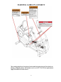
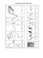
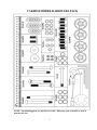
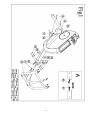
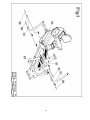
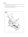
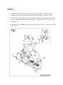
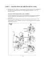
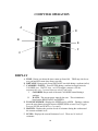
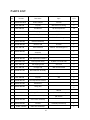
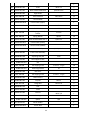
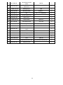
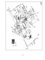
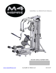
CS1 CARDIOSTRIDER
USER MANUAL
2
TABLE OF CONTENTS
BEFORE YOU BEGIN………………………..………………….……………..
3 IMPORTANT SAFETY NOTICES…………………………………………….
WARNING LABEL
PLACEMENT…………………………….……………….
4 CONTENTS OF PACKAGING……………………...………………………….
6 HARDWARE PACK……………………………………………………………
7 ASSEMBLY INSTRUCTIONS…………………………………………………
8‐18 COMPUTER OPERATION GUIDELINE……………………………...………
19‐20
5 PARTS LIST…………………………………………………….………………. 21‐23
EXPLODED DIAGRAMS………………………………………………………
WARRANTY……………………………………………..….………………….
.
24‐25
26‐27
BEFORE YOU BEGIN
Thank you for selecting the INSPIRE CARDIOSTRIDER. For your safety and benefit, read
this manual carefully before using the machine. As a manufacturer, we are committed to
providing you complete customer satisfaction. If you have any questions, or find there are
missing or damaged parts, please call our TOLL-FREE customer service number. Our
Customer Service Agents will provide immediate assistance to you.
Toll-Free Customer Service Number
1-877-738-1729
Mon. - Fri. 8 a.m. - 5 p.m. PST
www.inspirefitness.net
www.cardiostrider.com
3
IMPORTANT SAFETY NOTICE
PLEASE READ AND SAVE THESE INSTRUCTIONS
PRECAUTIONS
This exercise machine is built for optimum safety. However, certain precautions apply whenever you
operate a piece of exercise equipment. Be sure to read the entire manual before you assemble or
operate your machine. In particular, note the following safety precautions:
1. Keep children and pets away from the machine at all times. DO NOT leave children
unattended in the same room with the machine. The linkages on this machine can cause
serious injury or death if used improperly.
2. Never place your hands or feet in the path of the linkages because injury may occur to you or
damage may occur to the equipment. Never allow children to come near or approach the moving
linkages while in use.
3. Always engage the child safety lock after use. Information about assembly and engagement of this
lock is available in STEP 7 of the assembly process.
4. If the user experiences dizziness, nausea, chest pain, or any other abnormal symptoms, STOP the
workout at once. CONSULT A PHYSICIAN IMMEDIATELY.
5. Position the machine on a clear, leveled surface. DO NOT use the machine near water or outdoors.
6. Keep hands away from all moving parts.
7. Always wear appropriate workout clothing when exercising. DO NOT wear robes or other clothing
that could become caught in the machine. Running or aerobic shoes are also required when using
the machine.
8. Use the machine only for its intended use as described in this manual. DO NOT use attachments
not recommended by the manufacturer.
9. The braking system of this device is speed independent.
10. Disabled persons should not use the machine without a qualified person or physician in attendance.
11. Before using the machine to exercise, always do stretching exercises to properly warm up.
12. Never operate the machine if the machine is not functioning properly.
13. Maximum user weight 300 lbs (136 kg)
14. Allow 24” (61 cm) of space on each side of unit. Never place body parts under pivot area
(directly behind pedal)
CARE AND MAINTENANCE
1. Keep seat slider clean
2. Inspect and tighten all parts before using the machine.
3. The Frame and Seat Pad of the machine can be cleaned using a damp cloth and mild nonabrasive detergent. DO NOT use solvents.
WARNING: BEFORE BEGINNING ANY EXERCISE PROGRAM, CONSULT
YOUR PHYSICIAN. THIS IS ESPECIALLY IMPORTANT FOR INDIVIDUALS
OVER THE AGE OF 35 OR PERSONS WITH PRE-EXISTING HEALTH
PROBLEMS. READ ALL INSTRUCTIONS BEFORE USING ANY FITNESS
EQUIPMENT. Neither Health In Motion, LLC. nor FG1, LLC. ASSUMES ANY
RESPONSIBILITY FOR PERSONAL INJURY OR PROPERTY DAMAGE
SUSTAINED BY OR THROUGH THE USE OF THIS PRODUCT.
4
WARNING LABEL PLACEMENT
The warning labels have been placed on the unit in location shown. If the labels are
missing or illegible, please call customer service at 1-877-738-1729 for replacements.
Apply the labels in location shown.
5
CONTENTS OF PACKAGING
6
CARDIOSTRIDER HARDWARE PACK
NOTE: The following parts are not drawn to scale. Please use your own ruler or scale to
measure the size.
7
CARDIOSTRIDER ASSEMBLY INSTRUCTION
STEP 1 (see figure 1)
a) Remove contents of packaging leaving only the large styrofoam block supporting the rear
part of the unit. The center tube should protrude freely at the front as shown below.
b) Slide Front Frame Assembly (#43) up to Main Frame Assembly (#25). Assemble computer
connectors (#40 and #41).
c) Assemble Front Frame Assembly (#43) to Main Frame Assembly (#25) with qty 8 – M8x16
screws (#32), qty 8 – M8 lock washers (#38), and qty 8 – M8 washers (#3).
d) Remove the remaining large Styrofoam block at the rear of the unit. Place Rear Stabilizer
Tube Assembly (#16) underneath Rear Mounting Bracket. Ensure that the transport
wheels are facing backwards.
e) Attach the Rear Stabilizer Tube Assembly (#16) to the frame as with qty 2 - M8x70 carriage
bolts (#15), qty 2 - M8 Curved Washers (#17), and qty 2 – M8 Cap Nuts (#18).
8
9
STEP 2
a) Assemble Backrest Assembly (#7) onto Seat Slider Assembly with qty 1 – M8x70 bolt (#9),
qty 1 – M8 washer (#3), and qty 1 – Locking Cap Nut (#2).
b) Choose a preferred Seatback Recline Angle (See Figure B). The Backrest Assembly (#7)
may be installed in 3 different recline angles (FORWARD, MIDDLE, BACK) based on the
user’s preferred position. Align holes based on preferred seat position and place
Adjustment Pin (#5) through aligned holes.
c) Assemble Right Cam Lock Handle (#12) to Seat Slider Assembly and tighten the socket
screws (a). NOTE: ENSURE THAT THE RIGHT CAM LOCK HANDLE HAS AN
“R” STICKER.
d) Assemble Left Cam Lock Handle (#19) to Seat Slider Assembly and tighten the socket
screws (a). NOTE: ENSURE THAT THE LEFT CAM LOCK HANDLE HAS AN “L”
STICKER.
e) Assemble Seat Bottom Pad Assembly (#10) onto Seat Slider Assembly using qty 4 – M8
washers (#3) and qty 4 – M8 Cap Nuts (#18).
10
11
STEP 3
a) Assemble Right Pedal (#31) onto Right Pedal Arm Assembly (#24) using qty 2 – M6
Molded Plastic Nuts (#36) and qty 2 – 4.2x6 self tapping screws (#37).
b) Assemble Right Pedal Arm Assembly (#24) onto the Right Side Crank. NOTE: THERE
IS A SPACER INSIDE THIS PEDAL ARM PIVOT. WHEN ASSEMBLING PEDAL
ARM, PLACE FINGER INSIDE TO ENSURE THE SPACER IS CENTERED. THIS
ALLOWS THE PEDAL ARM TO SLIDE SMOOTHLY ONTO THE CRANK.
Secure using qty 1 – M8x20 Bolt (#22) and qty 1 – M8 Washer (#23).
c) Assemble Left Pedal (#28) onto Left Pedal Arm Assembly (#27) using qty 2 – M6 Molded
Plastic Nuts (#36) and qty 2 - 4.2x6 self tapping screws (#37).
d) Assemble Left Pedal Arm Assembly (#27) onto the Left Side Crank. NOTE: THERE IS
A SPACER INSIDE THIS PEDAL ARM PIVOT. WHEN ASSEMBLING PEDAL
ARM, PLACE FINGER INSIDE TO ENSURE THE SPACER IS CENTERED. THIS
ALLOWS THE PEDAL ARM TO SLIDE SMOOTHLY ONTO THE CRANK.
Secure using qty 1 – M8x20 Bolt (#22) and qty 1 – M8 Washer (#23).
12
13
STEP 4
a) Place Swing Arm Assembly (#21) onto the right side U-Bracket of the Front Frame
Assembly (#43). Secure using qty 1 – Ø10x75mm Shoulder Bolt (#39), qty 1 – M8
Washer (#3), and qty 1 – M8 Locking Cap Nut (#2).
b) Assemble Swing Arm Assembly (#21) to Right Pedal Arm Assembly (#24) using qty 1 –
Ø10x85mm Shoulder Bolt (#30), qty 1 – M8 Washer (#3), and qty 1 – M8 Locking Cap Nut
(#2).
c) Place Swing Arm Assembly (#21) onto the left side U-Bracket of the Front Frame Assembly
(#43). Secure using qty 1 – Ø10x75mm Shoulder Bolt (#43), qty 1 – M8 Washer (#3), and
qty 1 – M8 Locking Cap Nut (#2).
d) Assemble Swing Arm Assembly (#21) to Left Pedal Arm Assembly (#27) using qty 1 –
Ø10x85mm Shoulder Bolt (#30), qty 1 – M8 Washer (#3), and qty 1 – M8 Locking Cap Nut
(#2).
14
15
STEP 5
a) Place Right Handle Assembly (#11) onto Swing Arm Assembly (#21). Choose preferred
handle location and secure using Pop Pin (#29).
b) Place Left Handle Assembly (#20) onto Swing Arm Assembly (#21). Choose preferred
handle location and secure using Pop Pin (#29).
16
STEP 6
a) Connect Computer Console connector (b) to Upper Mast Cable (#34) and secure the
Computer Console (#26) to the Console Mast (#33) using qty 4 – M4 screws (#35).
b) Connect Upper Mast Cable (#41) to Main Console Cable (#34) and attach Console Mast
(#33) to Front Frame Assembly (#43) using qty 3 – M8x16 screws (#32) and qty 3 – M8
Washers (#17).
c) Connect the Power Adapter (#1) to the back of the Main Unit (#25). Connect to a 120VAC
power source.
17
STEP 7: CONNECTION OF CHILD SAFETY LOCK
a) IMPORTANT FINAL STEP: Screw threaded nut of CHILD SAFETY LOCK ASSEMBLY
(#42) onto the exposed bolt threads of the FRONT FRAME ASSEMBLY (#43). (see
FIGURE A below)
ENGAGING THE CHILD SAFETY LOCK ASSEMBLY
1. ALWAYS engage the CHILD SAFETY LOCK ASSEMBLY after each use by clipping it
onto the Locking Hook located under the LEFT PEDAL ARM ASSEMBLY (#27).
(FIGURE B).
2. Before each workout, disengage the clip from the Locking Hook under the pedal. The
CHILD SAFETY LOCK ASSEMBLY can then be clipped onto the front frame assembly
Stow Hook (FIGURE C).
18
COMPUTER OPERATION
A
D
B
E
F
C
DISPLAY
A. TIME: During a workout the time counts up from 0:00. TIME may also be set
as a goal and will count down from a set time.
B. DISTANCE: Keeps track of total DISTANCE traveled during a workout (miles)
C. CALORIES / WATTS: Press ENTER during a workout to toggle between
CALORIE view, WATTS view, or AUTO toggle (computer switches
automatically every 5 seconds between calories and watts)
I. CALORIES: Keeps track of the total CALORIES burned during a
workout.
II. WATTS: The current power input by the user. This calculation is
based on the RESISTANCE and SPEED.
D. TOGGLE WINDOW: Displays the SPEED (mph) or RPM. During a workout,
press the enter button to toggle between SPEED, RPM or Auto View (Toggles
between SPEED and RPM every 5 seconds).
E. MATRIX: Displays the previous levels of resistance during the workout and
the current resistance level
F. LEVEL: Displays the current Resistance Level. There are 16 levels of
resistance.
19
OPERATION
1. PRESS the START/STOP button to begin workout after computer boots up.
Time will count UP from 0:00
2. RESISTANCE: During a workout, press the UP or DOWN button to control the
workout resistance (Level 1 to Level 16)
3. Press and hold the ENTER or START/STOP key at any time to reset the
computer
4. A complete reset of the console may be completed by uplugging and replugging
the rear power inlet.
GOAL PROGRAMS
The CS1 computer console may also run a goal program in which the user reaches a Total
Calorie, Total Distance, or Total Time before the workout is complete.
1. When computer is in STOP mode, press the ENTER button to toggle between
TIME, DISTANCE, and CALORIES.
2. Press UP or DOWN to set a goal for the field you would like
3. Press START to begin your GOAL PROGRAM.
For example, if you would like to do a 300 calorie workout, Press ENTER (while computer
time is stopped) so CAL is blinking. Press the UP key to 300 and press START. You are
now running a program that will not stop until you have burned 300 calories.
20
PARTS LIST
Seq. Part No Part Name Spec Q'TY Power Adapter 120 VAC 1 1 RC801‐630‐001A 2 0110‐808‐008 Cap Nut M8 Black Zinc Plating 5 3 0116‐008‐010 Flat Washer φ8 electrophoretic 26 4 0114‐742‐198 Self tapping screw ST4.2*19 15 5 RC800‐391‐013 Lock pin φ8*63 1 6 0113‐208‐358A Allen head bolt M8*35 Thread length:15 2 7 RC801‐260‐002 Backrest Assembly 1 8 RC280‐400‐001 Backrest Pad PU foam 1 9 0113‐208‐708 Allen head bolt M8*70 Thread length: 10 1 10 RC801‐400‐001 Seat Bottom Pad Assembly 1 11 RC801‐331‐002 Handlebar R 1 12 RC800‐380‐002 Seat adjustment handle R 1 13 B650‐0001‐025 End Cap with wheel w/ Φ30*1.5 round tube 2 14 0114‐129‐138 Self tapping screw ST2.9*13 2 15 0111‐408‐718 Carriage bolt M8*70 half thread 2 16 RC800‐341‐002 Rear Stabilizer Assembly 1 17 0116‐608‐008 Arc Washer φ8mm 5 18 0110‐308‐008 Cap Nut M8 6 19 RC800‐380‐001 Seat adjustment handle L 1 20 RC801‐331‐001 Handlebar L 1 21 RC801‐300‐001 Swing Arm 2 22 0111‐008‐208A Hex head bolt M8*20 2 23 0116‐208‐508 Enlarged flat washer M8, Black Zinc Plating 2 Pedal Arm Assembly R φ8*δ2mm 1 24 RC801‐310‐001 25 RC800‐200‐000 Rear Frame Assembly 1 26 RC801‐630‐001 Console JS1012B (Customized) 1 Pedal Arm Assembly L 1 27 RC801‐310‐002 21
28 RC801‐801‐002 Left pedal 1 29 RC800‐801‐202 Knob M16*1.5 2 30 RC801‐561‐002 Allen head shoulder bolt φ10*82.5mm 2 31 RC801‐801‐003 Right Pedal 1 32 0113‐008‐168 Allen head bolt M8*16mm 11 33 RC801‐210‐001 Console Mast 1 34 RC801‐630‐001B Control cable (Upper) 1 35 0113‐104‐088 Allen Head bolt M4*8mm 8 36 0245‐006‐01 Molded Plastic Nut M6 4 37 0114‐742‐068 Self tapping screw w/ washer ST4.2*6 4 38 0116‐308‐010 Spring Washer φ8mm 14 39 RC801‐561‐001 Allen head shoulder bolt 1 φ10*71.5 2 40 RC801‐630‐001C Control cable (Lower) 1 41 RC801‐630‐001D Control Cable (Middle) 1 42 RC801‐561‐003 Steel Cable Clip φ2.5*φ8*142 1 43 RC801‐200‐002 Front Frame Assembly 1 44 RC800‐801‐020 Adjusting foot pad M10 2 45 RC801‐370‐001 Seat support frame 1 Rail 1 Self tapping screw ST4.2*8,F type 18 Mounting bracket δ2 1 46 47 48 RC800‐201‐019 0114‐142‐088 RC800‐201‐023 49 RC800‐801‐009 Rail Cover 50 0114‐129‐068 Self tapping screw 51 RC800‐801‐004 Main Cover R 52 BE480‐881‐005 Cap Nut 53 0110‐412‐599 Flange Nut 54 RC800‐801‐014 Disk 2 55 RC801‐240‐001 Crank 2 56 RC801‐221‐003 Hex nut M20*1.0 1 57 0171‐690‐002 Bearing 6904ZZ 2 Spacer φ25 1 58 RC801‐221‐002 1 ST2.9*6,F type 6 1 M25*1 M12*1.25 2 2 59 BC770‐801‐011 Sensor Holder 1 60 RC801‐630‐001E Sensor Wire 1 22
61 0113‐208‐218 62 RC801‐630‐001F 63 RC800‐221‐004 Hex socket pan head screws Motor, resistance adjustment M8*20 7 1 Bearing Cup 3 φ25 1 64 RC801‐220‐002 Belt wheel shaft φ260,J6, 1 65 0140‐206‐121 Belt 470,J6(FANGSHOU) 1 66 RC801‐630‐001G Console power cord 1 67 RC800‐801‐003 68 RC800‐391‐007 Main cover L 1 Plastic sleeve Φ10*41.5 1 69 0114‐142‐608 Self tapping screw ST4.2*60 1 70 0110‐410‐019 Flange Nut M10*1 (T: 7mm) 2 71 CN‐S21‐000 Fly Wheel Assembly 5KG dual direction 1 72 RC801‐601‐001 Resistance Adjustment Cable 73 RC801‐200‐001 Main Frame Assembly 1 74 0110‐708‐009 Locking Nut M8 1 75 RC801‐230‐001 Idler Assembly 1 76 GM575‐881‐005 Foot φ60*19 1 77 (S19)Crank Removal Tool w/ S19 crank vertical shaft 1 78 RC801‐891‐002 Hardware pack 1 23
1 24
25
Warranty
This Warranty applies to Inspire Cardio products manufactured or distributed by FG1 LLC. This Product is for
retail use only. It is NOT warranted for LIGHT-COMMERCIAL or HEALTH CLUB use.
CONSUMER USE:
10 YEAR FRAME:
Includes Main Frame and Welds
3 YEAR PARTS:
Excluding Paint and Finish (unless defective out of box)
1 YEAR LABOR
FG1, LLC. warrants that the Product you have purchased for personal, family or household use from FG1 LLC or from
an authorized FG1 reseller is free from defects in materials or workmanship under normal use during the warranty
period. Your sales receipt, showing the date of purchase of the Product, is your proof of the date of purchase. You
must demonstrate proof of purchase to obtain a warranty. This warranty extends only to you, the original purchaser. It
is not transferable to anyone who subsequently purchases the Product from you. It excludes expendable parts such as
paint and finish and cosmetic items, including, but not limited to the following: grips, seats and labels. This Warranty
becomes VALID ONLY if the Product is assembled / installed following the instructions / directions included with the
Product.
Replacement and repair of parts.
During the warranty period FG1 will, at no additional charge, repair or replace the Product if it becomes defective,
malfunctions, or otherwise fails to conform with this Warranty under normal personal, family, or household use. In
repairing the product, FG1 may replace defective parts with, at the option of FG1, serviceable used parts that are
equivalent to new parts in performance, or new parts. All exchanged parts and Products replaced under this warranty
will become the property of FG1. FG1 reserves the right to change manufacturers and or specification of any part to
cover any existing warranty.
Service procedures.
To obtain warranty parts, you must return the parts to FG1 or an authorized FG1 retailer in its original container (or
equivalent). You must pre-pay any shipping charges, taxes, or any other charges associated with transportation of the
Product. In addition, you are responsible for insuring any Product shipped or returned. You assume the risk of loss
during shipment. You must present FG1 with proof-of-purchase documents (including the date of purchase, Model,
and Serial Number). Any evidence of alteration, erasing or forgery of proof -of-purchase documents will be cause to
void this Warranty. Inspire compensates Servicers for warranty trips within their normal service area to repair
equipment at the owner’s location. You may be charged a trip charge outside the service area. Register your warranty
online visit www.inspirefitness.net
Conditions and Exceptions.
This Warranty does not extend to any Product not purchased from FG1 LLC or from an authorized FG1 reseller.
Labor claims must be authorized prior to performing service or they may be denied. This warranty does not extend to
any product missing a serial number or with a serial tag that has been altered or defaced. This warranty does not
extend to service calls to correct installation of the equipment or instruct owners on how to use the equipment. This
Warranty does not extend to any Product that has been damaged or rendered defective; (a) as a result of accident,
misuse, or abuse; (b) by the use of parts not manufactured or sold by FG1; (c) by modification of the Product; (d) as a
result of service by anyone other than FG1, or an authorized FG1 warranty service provider; (e) product that has not
been properly maintained (follow maintenance schedule found on product); (f) as a result of neglect. Should any
product submitted for Warranty service be found to be ineligible, an estimate of repair cost will be furnished and the
repair will be made if requested by you upon FG1 receipt of payment or acceptable arrangement of payment.
Disclaimer
EXCEPT AS EXPRESSLY SET FORTH IN THIS WARRANTY FG1 MAKES NO OTHER WARRANTIES;
26
EXPRESSED OR IMPLIED INCLUDING ANY IMPLIED WARRANTIES OF MERCHANTABILITY AND
FITNESS FOR A PARTICULAR PURPOSE. FG1, LLC. EXPRESSLY DISCLAIMS ALL WARRANTIES NOT
STATED IN THIS WARRANTY. ANY IMPLIED WARRANTIES THAT MAY BE IMPOSED BY LAW ARE
LIMITED TO THE TERMS OF THIS WARRANTY. NEITHER FG1 NOR ANY OF ITS AFFILIATES SHALL
BE RESPONSIBLE FOR INCIDENTAL OR CONSEQUENTIAL DAMAGES. FG1 IS NOT RESPOSIBLE FOR
THE REPAIR OR REPLACEMENT OF ANY PARTS THAT FG1 DETERMINES HAVE BEEN SUBJECTED
AFTER THE DATE OF MANUFACTURE TO ALTERATION, NEGLECT, ABUSE, MISUSE, NORMAL WEAR
& TEAR, ACCIDENT, DAMAGE DURING TRANSIT OR INSTALLATION, FIRE, FLOOD, OR ANY ACT OF
GOD. SOME STATES DO NOT ALLOW LIMITATIONS ON HOW LONG AN IMPLIED WARRANTY LASTS
OR THE EXCLUSION OR LIMITATION OF INCIDENTAL OR CONSEQUENTIAL DAMAGES, SO THE
ABOVE LIMITATIONS OR EXCLUSION MAY NOT APPLY TO YOU. This Warranty gives you specific legal
rights and you may also have other rights that may vary from state to state. This is the only express warranty
applicable to FG1’s “Inspire” branded strength products. FG1 neither assumes nor authorizes anyone to assume for it
any other express warranty.
27
28
FG1, LLC. / HEALTH IN MOTION, LLC.
4945 EAST HUNTER AVE. ANAHEIM, CA 92807
CS1.REVA
29