1
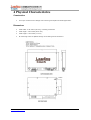
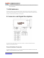
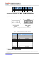
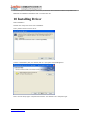
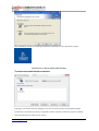
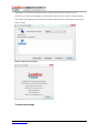
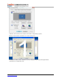
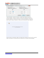
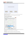
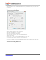
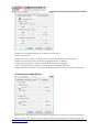
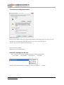
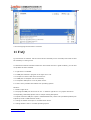
6000U Controller User manual
Version 1.01
Copyright ©2009-2010
by
Leadingtouch Technology Co., Ltd
HuiLongGuan LongXiang industrial center,ChangPing,Beijing,China
www.leadingtouch.com
Tel:+86-51090978
http://www.leadingtouch.com
Fax:+86-51090979
E-mail:[email protected]
1/23
Content
CONTENT ..............................................................................................................................................1
1 PRECAUTIONS ..................................................................................................................................3
2 PACKAGE CONTENTS ....................................................................................................................3
3 INSTALLING AND CONNECTING.................................................................................................4
4 PHYSICAL CHARACTERISTICS ...................................................................................................6
CONSTRUCTION ....................................................................................................................................6
DIMENSIONS .........................................................................................................................................6
5 ELECTRICAL.....................................................................................................................................7
SUPPLY VOLTAGE AND CURRENT ..........................................................................................................7
USB INTERFACE ...................................................................................................................................7
OPERATING MODES ..............................................................................................................................7
TOUCH RESOLUTION ............................................................................................................................7
CONVERSION TIME ...............................................................................................................................7
RELIABILITY .........................................................................................................................................7
6 ENVIRONMENTAL ...........................................................................................................................8
TEMPERATURE ......................................................................................................................................8
HUMIDITY ............................................................................................................................................8
OPERATING ALTITUDE ..........................................................................................................................8
SHOCK AND VIBRATION ........................................................................................................................8
ESD: CONTROLLER ALONE ..................................................................................................................8
FLAMMABILITY ....................................................................................................................................8
7 LED INDICATORS.............................................................................................................................9
8 CONNECTORS AND SIGNAL DESCRIPTIONS...........................................................................9
9 AGENCY APPROVALS ...................................................................................................................10
10 INSTALLING DRIVER.................................................................................................................. 11
11 FAQ ...................................................................................................................................................20
www.leadingtouch.com
2/23
1 PRECAUTIONS
Touchscreen is made of glass material. It’s easily breakable from dropping or impact, please
handle it with care.
Please pull the plug and contact the sales dealer immediately when you smell a bit of unpleasant
odor out of touchscreen.
Please do not plug-in and plug-out frequently when the computer is on.
Please clean the front and rear surface of touchscreen in order to make it best performance.
Please do not screw it tight when mounting the touchscreen (i.e. it is desirably fixed up) for fear of
deformation.
Please contact the sales dealer if there are not adequate components to your touchscreen.
New touch screen system comprising of: package contents including touchscreen and PC
connection cables, control card, quality-assured card, installation disc including driver and manual.
2 Package contents
Touchscreen
PC connection cables
Control card
(USB, serial or Comb cable, depending on the model you chose)
or
or
Touchsceen
www.leadingtouch.com
3/23
Standard USB cable 14-211-180
Detached USB cable 14-212-040&14-213-180
Control card 6000U
3 Installing and connecting
Mount touchscreen on monitor and then connect it to PC with cable and control card as following
steps
Standard USB cable connecting
1. Connect touchscreen 12pin port to 12pin connector of control card.
2. Connect cable 14-211-180 4 pin connector to 4pin connector of control card.
3. Connect 14-211-180 USB port to PC USB port.
www.leadingtouch.com
4/23
5. Connect 14-211-180 GND ring to ground.
Detached USB cable connecting
1. Connect touchscreen 12pin port to 12pin connector of control card.
2. Connect cable 14-212-040 4 pin connector to 4pin connector of control card.
3. Connect 14-212-040 USB port to 14-213-180 USB port.
5. Connect 14-213-180 USB port to PC USB port.
www.leadingtouch.com
5/23
4 Physical Characteristics
Construction
•
Four-layer surface-mount design with internal ground plane for EMI suppression.
Dimensions
•
Total width: 2.45 inches (62 mm), including connectors
•
Total length: 3.45 inches (87.5 mm)
•
Total height: 0.44 inches (11 mm)
•
All mounting holes are plated through for chassis ground connection.
www.leadingtouch.com
6/23
5 Electrical
Supply Voltage and Current
•
+5 VDC, nominal (+4.75 to +5.25 VDC)
•
60mA typical, 75mA maximum at +5 VDC. Typical power dissipation is 300mW at 5V.
•
Minimum power-supply 200 mA.
•
Inrush current of up to 500mA for 50mS.
•
Total noise and ripple must be less than 100 mV (p-p) for frequencies below 1 MHz, and
less than 50 mV (p-p) for frequencies above 1 MHz.
USB Interface
•
The 6000U-K05D controller is an interrupt-type, full-speed USB device.
Operating Modes
•
Leadingtouch protocol
•
Customer specific protocol
•
Initial/ Stream/ Untouch Modes
Touch Resolution
•
4096x4096, size independent
Conversion Time
•
Approximately 10 ms per coordinate set
Reliability
•
MTBF greater than 1,543,000 hours per MIL-HDBK-217-F2 calculated by parts stress
method in ambient environment.
www.leadingtouch.com
7/23
6 Environmental
Temperature
•
Operating: 0°C to 65°C
•
Storage: -25°C to 85°C
Humidity
•
Operating: 10% to 90% RH, noncondensing
•
Storage: 10% to 90% RH, noncondensing
Operating Altitude
•
10,000 feet
Shock and Vibration
•
The controllers, with Leadingtouch standard container, can meet International Safe
Transit Association project 2A test procedure.
ESD: Controller Alone
•
Per EN 6100-4-2 1995. Level 4
•
Contact Discharge - 8kV
•
Air Discharge - 15kV positive and negative polarity
•
P2 and P3 USB pins 1, 3 and 4 are tested using an ESD generator equipped with a standard
finger probe and set to 15kV. The ESD generator is applied to the series A receptacle at the
host end of a 1m USB cable, which is plugged into the controller USB series B receptacle.
The controller is powered up and grounded.
The controller may not function correctly after test, however, it should work normally after reset or
recycle of the supply. The ESD tests will be conducted with the controller integrated into a monitor
with the controller and the ESD generator grounded to the monitor chassis.
Flammability
www.leadingtouch.com
8/23
•
The PCB substrate is rated 94V0. All plastic components, such as headers and connectors,
are also rated 94V0.
7 LED Indicators
The 6000U controller has one LED status indicators. When 6000U controller initially connects to
host, the LED will be constantly on. Then when touchscreen connects to 6000U, the LED will snuff
out after 3 seconds and be constantly on during touch.
8 Connectors and Signal Descriptions
All connectors are located along one side of the controller. Connector descriptions and pin
definition are as following sections.
Power/Interface Connector
The power/interface connector, P2, is a 1X4,2.0mm Female connector on board for connection with
USB port. The pins definitions are shown in Table 1.
www.leadingtouch.com
9/23
Table 1 Power/Interface Connector P2 Pin definition
P2
Signal
Signal
P2
Signal
Signal
Pin
Name
Function
Pin
Name
Function
1
GND
Ground
2
D+
USB D+
3
D-
USB D-
4
Vcc
+5V Power
Touchscreen Connectors, J2, and Signal Descriptions
The touchscreen connector, J2, is a dual row by six position header with 0.025 inch square pins
spaced on 0.100 centers.
Figure 1
Pin Diagram for Touchscreen Connector, J2
Table 6 Touchscreen Connectors, J2, Pins definition
Signal name
J2 pin
Signal function
Chassis
1
frame ground for cable shield
none
2
connector key
Y rcv +
3
Y+ receiver
Y xmt +
4
Y+ emitter
Y rcv -
5
Y- receiver
Y xmt -
6
Y- emitter
analog gnd
7
analog ground
X xmt -
8
X- emitter
X rcv -
9
X- receiver
X xmt +
10
X+ emitter
X rcv +
11
X+ receiver
none
12
connector key
9 Agency Approvals
The touch system including 6000U controller, touchscreen and connection cable has certified with
FCC Part 15.
www.leadingtouch.com
10/23
The touch system including 6000U controller, touchscreen and connection cable is compatible with
EN55022 and EN55024 standards and is certified with CE.
10 Installing Driver
Start installation
Double click setup.exe file to start installation.
Firstly install resource kit for driver
Choose a installation path, the default path is C:\Program files\Leadingtouch.
There are two setup type: complete and Custom. The default one is complete type.
www.leadingtouch.com
11/23
After installation, double click LeadingTouchSetup on desktop to enter calibration program.
Introduction to driver setup and function
Touchscreen administration interface
Language: can choose interface language, now has two choice Chinese and English language.
Touchscreen: All touchscreen can be recognized is shown in the box, choose the right one calibrate
and click Setting(S) to continue your setting.
www.leadingtouch.com
12/23
COM Port(P): For serial interface touchscreen, please select the right COM port for your
touchscreen to continue setting(Note: COM interface touchscreen can’t not be recognized autoly,
user need to select COM port manually and click Add to add touchscreen into computer as following
picture shows).
Driver version information
Touchscreen setting
www.leadingtouch.com
13/23
Calibrate: show monitor and resolution information recognized by system
Identify: show monitor information to current touchscreen.
Custom: to define custom calibration area by changing drag Left-Top and Right-Bottom
coordinate to set calibration area.
www.leadingtouch.com
14/23
4 points calibration: calibrate by 4 points, for SAW and Infrared touchscreens.
9 points calibration: calibrate by 9 points, for 4W, 5W and capacitive touchscreen.
25 points calibration: calibrate by 25 points, for 4W, 5W and capacitive touchscreen.
Select 4 points, 9 points, 25 points or custom and click calibrate to start calibration.
Press the center of red point for about 2-3 seconds. Don’t release your finger until the red point
shaft to next position or hearing beep sound. Repeat for all red point to finish calibration.
www.leadingtouch.com
15/23
After calibration, you can choose:
Recalibrate: If mouse cursor can’t overlap with your touch finger, please select this item to
calibrate touchscreen again.
DrawLine: Select to enter draw-line test, for more details refer to next chapter
Touchscreen setting- Adjust
Border adjust: adjust screen border scale border to fit current touchscreen, as touchscreen may
have abnormal action caused by installation or non-linear problem.
Touch mode:
Click On Touch: indicates the response when your finger touches on the panel
Click On Release: indicates the response when your finger leaves the touchs panel
Click On Touch No Move: indicates the response when your finger touches on the panel, can’t draw
www.leadingtouch.com
16/23
line and drag
Click On Release No Move: indicates the response when your finger leaves the panel, can’t draw
line and drag
Touchscreen setting-Buttom
[Button Switch]: Enable Auto Right Button Switch
Auto range: Click effectual in 10mm area
Auto time: Click effectual in 1000mMsec
Auto right button effects only when above two items effectual.
[Double Click Setting]:
Range: Clicks in range of 10 mm are determined to be a touch point
Time: Clicks in 500 msec are determined to be a touch point
If any icon or program can’t open normally, please drag the two rules above to right side a little.
Touchscreen setting-Advanced
www.leadingtouch.com
17/23
[Enable Touch]: Enable or disable touch function of touch panel
[Advanced Function]:
Enable Const Touch Function: The range of 10 mm are determined to be a touch point
Enable Line Continue Function: Settings for handwriting input or drawing.
Range: Disconnected line in range of 20mm will be amended by algorithm
Time:
Disconnected line in range of 100msec will be amended by algorithm
Enable Line Smooth Function: Line can be smoothed by algorithm to insert 5points in 15mm range
Touchscreen setting-Sound
Beep on touch
the speaker on the computer will generate voice when touch on the touchscreen
Beep on release
www.leadingtouch.com
the speaker on the computer will generate voice when leave off the touchscreen
18/23
Touchscreen setting-Information
[Screen information]
Select: Click to select current touch panel size and model to amending function if mouse cursor not
overlap with your finger after calibration. Default size is from 3.5inch to 42 inch
Custom: Click to input a custom touch panel size
[Control Card information]
Indicate Control Card information
Uninstall Leadingtouch drivers
Enter Touchscreen Uninstall program through the following programmer
1 Click “Start”----“programmer”----“Leadingtouch” ----“Uninstall”
2 Open control panel and select “Leadingtouch Driver for Window” ----“delete”
www.leadingtouch.com
19/23
3. Run setup program and select “uninstall”.
11 FAQ
Q: Touchscreen no reaction. LED on control card is constantly on for 3 seconds, then snuff out and
be constantly on during touch.
A: Phenomenon below indicates touchscreen and control card are in good condition, you can find
out problem as below method.
1: if right driver is installed.
2:If COM port selected in program is the right one in use.
3:If Jumper on control card meet current driver.
4:If COM port of computer can work normally.
5:If computer COM port is in use by other device.
6:If there is any mistake information from operating system.
Solution:
1: Install a right driver
2:Set program COM port as the one in use. 3:Install a right driver. For jumpers and driver
corresponding relationship please refer to Jumper setting description.
4:Inspect if Serial or USB port is open in mainboard bios file, if there is any hardware problem(can
inspect by serial or USB interface mouth).
5:Change to another serial port or uninstall other device.
6:Change another host or re-install operating system.
www.leadingtouch.com
20/23
Q: Touch no action and LED constantly on.
A: This indicate touchscreen and control card are not in good preparation, please check following
below steps
1:If space in monitor or cabinet for touchscreen is enough, transducers on touchscreen may be
crushed.
2:If protected film is tear off
3:If reflection texture in touchscreen is dirty.
4:If adopts wrong dust-proof strips or assemble it too tight.
5:If Control card temperature is too high.
6:If 12pin cable, signal cable on touchscreen, or control card is broken.
Solution
1:Change another monitor, cabinet or touchscreen.
2:Tear off protected film
3:Clean touchscreen
4:Adopts right dust-proof strips and assemble them not too tight.
5:Remove control card to ventilated environment
6:Change another touchscreen or control card.
Q: Touch no reaction, LED flickers.
A: That indicate a communication mistake between touchscreen and control card. Please settle it
as following steps
1:Check if power supply for control card is unstable.
2:Check if there is water or other dirty on touchscreen.
3:Check if cable connected to touchscreen and control card is loosing.
4:Check if touchscreen and control card is broken.
Solution:
1:Change another host or adopt a stable power.
2:Clean touchscreen and restart computer.
3:Re-connect touchscreen and control card.
4:Change another touchscreen or control card
Q: Touch no reaction, LED is off constantly.
A: That indicate there is no current through control card. Please check as following steps.
1:Check if 232 or USB cable is not in good condition or connection.
www.leadingtouch.com
21/23
2:Check if power cable is not in good condition.
3:Check if control card is not in good condition.
Solution
1:Re-connect cable or change another cable
2:Change another power cable
3:Change another control card
Q: Cursor not move with finger, has deviation.
A: This is caused by inaccurate calibration, please check according to following directions.
1:Check if calibrate touchscreen uncorrectly.
2:Check if changed resolution without re-calibration
3:Check if jumper setting on control card meets current driver
4:Check if touchscreen is dirty
5:Check if control card temperature is too high to work normal, and if there is influence from other
high frequency device.
6:Check if touchscreen and control card is in good condition
Solution
1:Redo calibration test, be sure let your finger overlap with red circle center in calibration
2:Redo calibration test
3:Setup right jumper and driver and redo calibration
4:Clean touchscreen
5:Remove control card to low temperature and influence place
6:Change another touchscreen or control card
Q: Cursor jump all around during touch, LED flickers
A: The phenomenon seldom happen, you can follow below steps to solve it.
1:Check if use unqualified dust-proof strips to crush touchscreen reflection texture too tightly
2:Check if there is water or other contamination on touchscreen surface.
3:Check if control card temperature is too high to work normal, and if there is influence from other
high frequency device.
4:Check if control card power supply is unstable
5:Check if touchscreen or control card is defective
Solution
1: Use qualified drst-proof strips and don’t assemble it too tight
2:Clean touchscreen
www.leadingtouch.com
22/23
3:Remove control card to low temperature and influence place
4:Change another host or provide a stable power supply
5: Change another touchscreen or control card
Q: Cursoer can’t move, LED flickers
A: This usually caused by software mistakes, please solve it as following instructions
1:Check if calibrate uncorrectly
2:Check if jumper setting on control card meets current driver
3:Check if there is water or other contamination on touchscreen surface, or host is hang over
4:Check if adopt unqualified dust-proof strips or assemble touchscreen uncorrectly.
Solution:
1:Redo calibration
2:Make certain driver is correct installed and redo calibration
3:Clean touchscreen and restart computer
4:Adopt qualified dust-proof strips and assemble it not too tight
Q: A band area in screen is no touch action or must touch with great stress.
A: That is a signal attenuation phenomenon in that area, may caused by improper assembly or
dust.
1 Check if touchscreen and monitor front frame is separated by our dust-proof strips
2 Check if there is dust accumulated on touchscreen reflection texture
3 Check if touchscreen assembly is too tight to transmit signal
Solution
1 Adopt our dust-proof strips to separate touchscreen and monitor front frame
2 Clean touchscreen reflection textrue
3 Loosing touchscreen and monitor front frame
All the rights reserved by Leadingtouch
www.leadingtouch.com
23/23