1
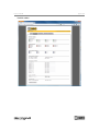
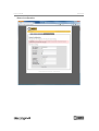
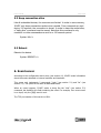
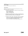
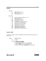
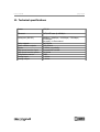
User's manual
v0.8
User's manual
page 2/25
Índice
1. Introduction..................................................................................................................3
2. Hardware description...................................................................................................3
2.1. Connection blocks...........................................................................................................4
2.2. Serial port (RS-232)........................................................................................................5
4. Web server.....................................................................................................................6
5. Command server.........................................................................................................10
5.1 Authentication................................................................................................................10
5.2 Variable set.....................................................................................................................10
5.2 Status...............................................................................................................................11
5.3 Keep connection alive.....................................................................................................12
5.3 Reboot.............................................................................................................................12
6. Event server................................................................................................................12
7. IO.XEC responses......................................................................................................13
8. Serial server................................................................................................................13
9. Factory defaults..........................................................................................................14
10. Configuration tool....................................................................................................15
10.1 Hardware features........................................................................................................15
10.2 Internal variables.........................................................................................................18
10.3 Logical Controller........................................................................................................19
11. Technical specifications...........................................................................................25
User's manual
page 3/25
1. Introduction
IO.XEC is a device that captures electrical signals, and transmits this information
through a TCP/IP connection, in an Ethernet network. It implements the following TCP
applications:
•
•
•
•
Web server (port 80)
Event server (port 8200)
Command server (port 8201)
Serial(RS232)-Ethernet bridge (port 9761)
2. Hardware description
Ports:
Ethernet
Serial (RS232)
Inputs:
8
1
1
1
general purpose digital inputs (several configurations are possible)
fast digital input, designed for incremental encoders
analogue temperature input (the recommended sensor is LM35)
analog input (0-10V)
Outputs:
3 relay digital outputs
5 open collector digital outputs
1 analog output (0-10V)
User's manual
page 4/25
2.1. Connection blocks
Bloco de terminais CON2
The connection blocks are accessible after opening the device's enclosure.
Bloco de terminais CON1
Power supply
CON 1
GND 12Vdc
1
2
CON 1
3
4
5
6
7
8
OUT7
OUT6
OUT5
OUT4
OUT3
OUT0
OUT1
OUT2
NO CMNC NO CMNC NO CMNC
COM OUT
Digital outputs
9 10 11 12 13 14 15 16 17
User's manual
page 5/25
IN7
IN6
IN5
IN4
IN3
IN2
IN1
IN0
COM IN
Digital inputs
CON 1
18 19 20 21 22 23 24 25 26
2.2. Serial port (RS-232)
RJ11
2
↔
4
↔
5
↔
RS232(DB9)
5
3
2
User's manual
page 6/25
4. Web server
The web server is available with a standard browser. The device's status and
configuration can be viewed and changed accessing the various pages. The default
username and password required to login are “admin” e “xec”, respectively.
Home page
User's manual
Variable status
page 7/25
User's manual
Upload of configuration file
page 8/25
User's manual
Network configuration
page 9/25
User's manual
page 10/25
5. Command server
The command server makes it possible to control and get status of the device. It
allows to activate the outputs and get the status of all the variables. In order to access
this service, a TCP socket must be created to the device, on port 8200. The default
username and password required to login, are “admin” and “xec”, respectively. The
TCP port number is 8200. All the commands must be terminated with <!>.
The variables whose status can be retrieved, and activated, are:
Qx: digital outputs
Bx: internal bits
C0: high speed counter
Nx: internal numerical variables
AO: analog output
Ix: digital input
AI0: analog input
AIT: analog temperature input
x: 0..8
x: 0..7
x: 0..7
x: 0..7
5.1 Authentication
Syntax: LOGIN, user,pass<!>
user: user name
pass: password
5.2 Variable set
All the settable variables above, can be set with this command.
Syntax: SET,var,val[,timer]<!>
var:
val:
Qx/Bx/C0/Nx/AO
0/1/T: Qx/Bx
-2147483648..2147483647: Nx/Cx
0..1000: AO
timer: 0..9999: Qx/Bx (in 1/10s)
User's manual
page 11/25
5.2 Status
If the STAT command is issued, the status of all the variables is retrieved.
Syntax: STAT<!>
The response of the command has several fields, according to the variable
type:
[IQB]=iiiiiiiiqqqqqqqqbbbbbbbb
i...:
q...:
b...:
i,q,b:
i,q,b:
i:
i,q,b:
i,q,b:
i:
i:
i:
[NMx]=y
x:
y:
[CN0]=y
y:
[AIx]=y
x:
y:
[AO]=y
y:
Digital variables
8 inputs
8 outputs
8 internal bits
f: variable is false (inactive)
t: variable is true (active)
r: push button is released
F: variable changed to false
T: variable changed to true
S: push button was pressed for a short time
L: push button was pressed for a long time
R: push button was pressed for a long time, and released
Value of numerical variables
0..7
-2147483648..2147483647
Value of the high speed counter
-2147483648..2147483647
Value of analog inputs
0, T
0..1000
Value of analog output
0..1000
User's manual
page 12/25
5.3 Keep connection alive
Like all embedded devices, the resources are limited. In order to save memory,
IO.XEC only keeps connections active when needed. If no commands are sent
during 120 seconds, the connection is closed. In order to keep the socket alive,
a “keep alive” command must be issued. Note that this command is only
needed if no other commands are sent for a 120 seconds period.
Syntax: KA<!>
5.3 Reboot
Reboots the device.
Syntax: REBOOT<!>
6. Event server
According to the configuration that is done (see section 10), IO.XEC sends information
about the events detected on internal variables and hardware.
This server only implements 2 commands: “login” (see section 5.1) and “ka” (see
section 5.3). The syntax is the same as described before.
When an event happens, IO.XEC sends a string like the “stat” (see section 5.2)
command, but limited to the field containing the event. For example, if an event occurs
in an input, only the [IQB] event is sent.
The TCP port number of this service is 8201.
User's manual
page 13/25
7. IO.XEC responses
Welcome!
Connection successfully opened
[OK]
Command successfully executed
[ERR]:100
[ERR]:200
[ERR]:300
[ERR]:400
[ERR]:500
[ERR]:800
[ERR]:900
Invalid command
Argument error: invalid variable
Argument error: invalid value
Argument error: invalid number of arguments
Login error
Command not allowed
Login not performed
8. Serial server
The serial server is a transparent bridge between a TCP socket and a serial port
(RS232). After a connection is established, all the bytes received on socket are
dispatched through the serial port, and all the bytes that arrive on the RS232 port are
forward to the TCP connection. The TCP port number is 9761. The baud rate of the
serial port is selected using the configuration tool (see section 10).
User's manual
page 14/25
9. Factory defaults
When IO.XEC is connected for the first time, it has the following network configuration:
DHCP:
IP address:
Subnet mask:
NetBIOS name:
Username:
Password:
active
169.254.1.1 (in case there is no DHCP server)
255.255.0.0 (in case there is no DHCP server)
XEC
admin
xec
To restore factory default parameters, locate the push-button on the board and do the
following:
•
•
•
•
turn off IO.XEC
press and hold the push-button
turn on the device
hold the push-button pressed for at least 5 seconds, during boot.
User's manual
page 15/25
10. Configuration tool
The configuration tool, allows to:
•
•
•
•
•
•
•
•
name the various variables, with suitable labels. These labels will be use to
identify the variables in the web server
define the type of hardware that is connected to the inputs
configure the events that are sent through the event server
define the baud rate of the serial port
define the time zone properties
implement some automation features
send configuration to IO.XEC
make test connections to the command and event server
10.1 Hardware features
User's manual
page 16/25
In this tab, the hardware is configured according to the application needs.
Inputs
In the inputs section, you can define, for each input:
•
•
•
the label
the type
◦ standard (a regular contact)
◦ push-button
the events that are captured and sent through the event server
Analog
In the analog section, you can define:
•
•
•
the label
the value of the analogue output on power up
the value variation that has to occur, in order to create an event
Counter
In this section, you can define:
•
•
•
•
•
the
the
the
the
the
label
value of the counter on power up
type of counter
value variation that has to occur, in order to create an event
divider (number of pulses detected to increment the counter)
Digital outputs
In this section, you can define:
•
•
•
the label
the value of each output on power up
the events that are captured
User's manual
page 17/25
TCP-serial bridge
Here you can define the baud rate of the RS232 port.
Time definitions
IO.XEC has an internal clock that synchronizes to ntp.org time server. In order to
adjust local time settings it can be defined:
•
the time zone, in terms of hours. For instance, if the device is located in:
◦ Lisbon, 0:00 should be used
◦ Paris, 1:00 should be used
◦ Azores, -1:00 should be used
◦ Helsinki, 2:00 should be used
•
Daylight Saving Time (DST) start and end patterns. These patterns have
four sections, separated by a dot (.). You can setup the day, month, day
of week, and hour where the DST start or end takes place.
•
The syntax is: <month>.<day>.<day of week>.<search>. For example:
◦ 04.01.6+2.2:00: start DST on the second Sunday of April, at 2:00
◦ 03.31.6-1.2:00: start DST on the last Sunday of March, at 2:00
◦ 03.31...2:00: start DST on the 31th March, at 2:00
◦ 10.31.6-1.2:00: end DST on the last Sunday of October, at 2:00
User's manual
10.2 Internal variables
Digital internal variables
They act as virtual IOs. It can be configured:
• the label
• the value on power up
• the events that are captured
page 18/25
User's manual
page 19/25
Numerical variables
These variables have length of 32bit (signed). It can be defined:
•
•
•
the label
the value on power up
the value variation that has to occur, in order to create an event
10.3 Logical Controller
The logical controller allows to implement automation functions. The device can
perform calculations logical combinations of the various variables (internal and
external).
User's manual
page 20/25
Variables
1. Boolean
• Ix
• Qx
• Bx
•
2. Numerical
•
•
•
•
•
•
•
•
•
•
•
•
Nx
C0
AO
AI0
AIT
TS
TM
TH
DD
DM
DY
DW
Digital input Ix, x: 0..7
Digital output Qx, x: 0..7
Internal bit Bx, x: 0..7
Numerical internal variable Nx, x: 0..7
High speed counter
Analog output (0..1000)
Analog input (0..1000)
Temperature analog input (0..90)
Internal clock: current second
Internal clock: current minute
Internal clock: current hour
Internal clock: current day
Internal clock: current month
Internal clock: current year
Internal clock: current week day
Function EVENT
This function detects an event on a digital IO or internal bit. Returns true when the
event occurs
Syntax:
var:
EVENT(var,event)
Ix/Qx/Bx
event: T: variable turns to true
F: variable turn to false
S: when a short push occurs in a push button
L: when a long push occurs in a push button
R: when a push button is released, after a long push
User's manual
page 21/25
Function IS
Returns true if the logical value of a digital IO or internal bit equals the value
parameter. Returns false, otherwise.
Syntax:
var:
IS(var,value)
Ix/Qx/Bx
event: T: variable is true
F: variable is false
S: during a short push in a push button
L: during a long push in a push button
R: after a push button is released
Function COMPARE
Returns the result (true or false) of the comparison between two numerical variables,
using a comparison operator.
Syntax:
COMPARE(var1,operator,var2)
var1: Nx/C0/AI0/AIT/AO/TS/TM/TH/DY/DM/DD/DW
var2: Nx/C0/AI0/AIT/AO/TS/TM/TH/DY/DM/DD/DW/x(32bit value)
event: >: returns true, if var1 is greater than var2
<: returns true, if var1 is less than var2
>=: returns true, if var1 is greater than or equal to var2
<=: returns true, if var1 is less than or equal to var2
!=: returns true, if var1 is different var2
User's manual
page 22/25
Function SET
If a true condition is met, assigns a value to a variable. This functions has 3 variations,
depending on the variables and parameters used.
Syntax 1:
SET(var)
Sets the value of the condition to var
var:
Syntax 2:
var:
Ix/Qx/Bx
SET(var,value[,tmr])
Sets var to value, if the condition is true. Does nothing
otherwise.
Ix/Qx/Bx
value: 0 (false) / 1 (true) / T (toggle)
tmr:
Syntax 3:
timer in 1/10s. optional.
SET(var1,var2)
Sets var1 with the value of var2, if the condition is true. var2 can
contain simple calculations, such as N4+10; C0*N1. Does
nothing otherwise.
var1: Nx/C0/AI0/AIT/AO/TS/TM/TH/DY/DM/DD/DW
var2: Nx/C0/AI0/AIT/AO/TS/TM/TH/DY/DM/DD/DW/x(32bit value)
simple calculations allowed.
User's manual
page 23/25
Syntax
The syntax is very simple. The automation concept is organized in lines, each one
divided in two sections (left and right).
The lines are executed one after the other. When the processor reaches the lats lien, it
jumps to the first one. While the logic controller is active, this process is repeated
endlessly.
As stated, each line has two sections: left and right. On the left, the combination of
events and status is performed using the functions IS, EVENT and COMPARE and the
following operators:
•
•
•
•
*: logical AND
+: logical OR
^: logical XOR
(): parenthesis to implement priorities in the evaluation
On the right a SET operation must be defined. According to the syntax used, an action
is performed. Some examples ar provided:
•
Toggle Q0, when I0 is active:
event(i0,t)=set(q0,t)
•
If I0 is true and I1 or I2 are true, activate Q1. Deactivate Q1 otherwise
is(i0,t)*(is(i1,t)+is(i2,t))=set(q1)
•
Blink an output every second:
compare(ts,!=,ts)=set(q1,1,5)
• Count the number of seconds that an input is active
is(i3,t)*compare(ts,!=,ts)=set(n0,n0+1)
Multiple lines can be added to achieve the required automation. The number of lines is
limited by the available memory. The configuration tool indicates how much memory is
occupied by the written lines.
Two blocks can be added. The first block is executed one time, in order to initialize the
process. The second is iterated.
The behavior of the logic controller on power up, can be one of the following:
•
•
•
Don't start: It can be started through the web page.
Start immediately: After the reboot, as soon as possible
Start after a successful time update. Waits until the NTP server is available and
an update to the current time is performed. It needs an Internet connection
The logic controller status is shown in the web server.
User's manual
page 24/25
11. Technical specifications
Power
12V/1A
Ethernet
10T/100T base @ 10Mbit/s
Serial port (RS-232)
4800bps / 9600bps / 19200bps / 57600bps /
115200bps
no parity, no flux control
6A/230Vac
12V/150mA
5-24Vdc, no polarity
Incremental encoder
10-30Vdc
LM35
0-10Vdc
0-10Vdc
Relay outputs
Open collector outputs
Inputs
High speed counter input
High speed counter power
Temperature sensor
Analog input
Analog output
User's manual
page 25/25