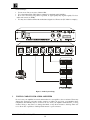
1
KRAMER ELECTRONICS, Ltd.
USER MANUAL
Distribution Amplifiers:
Models: VM-1110, VM-1610, VM-5AD, VM-80A
IMPORTANT: Before proceeding, please read paragraph entitled
"Unpacking and Contents"
Table Of Contents
Section
Name
Page
1
1.1
1.2
2
3
4
4.1
5
5.1
5.2
5.3
5.4
6
6.1
7
8
8.1
8.2
8.3
8.4
8.4.1
8.5
8.6
8.7
9
10
10.1
10.2
INTRODUCTION
A Word On Distribution Amplifiers
Factors Affecting Quality of Results
SPECIFICATIONS
How do I Get Started?
UNPACKING AND CONTENTS
Optional Accessories
VM SERIES AMPLIFIERS
Getting to Know Your VM-1110 Amplifier
Getting to Know Your VM-1610 Amplifier
Getting to Know Your VM-5AD Amplifier
Getting To Know Your VM-80A Amplifier
INSTALLATION
Rack Mounting
Connecting to Audio Devices
USING THE VM AUDIO AMPLIFIERS
Powering On the Amplifier
Coupling
Audio Control (VM-1610/80A Only)
Balanced\Stereo Control (VM-5AD Only)
Using A Microphone
Programming the VM-1110 and VM-1610
Programming the VM-80A
Audio System Setup
TAKING CARE OF YOUR AUDIO AMPLIFIER
TROUBLESHOOTING
Power and Indicators
Audio Signal
2
2
2
3
4
4
4
5
5
6
7
9
9
9
9
9
9
9
9
9
10
10
10
10
11
11
12
13
Figure
1
2
3
4
5
List Of Illustrations
VM-1110 Front/Rear Panel Features
VM-1610 Front/Rear Panel Features
VM-5AD Front/Rear Panel Features
VM-80A Front/Rear Panel Features
Audio System Setup
Page
5
6
7
8
11
List Of Tables
Table
1
2
3
4
VM-1110 Front/Rear Panel Features
VM-1610 Front/Rear Panel Features
VM-5AD Front/Rear Panel Features
VM-80A Front/Rear Panel Features
5
6
7
8
INTRODUCTION
Congratulations on your purchase of this Kramer Electronics amplifier. Since 1981 Kramer has been
dedicated to the development and manufacture of high quality video/audio equipment. The Kramer
line has become an integral part of many of the best production and presentation facilities around the
world. In recent years, Kramer has redesigned and upgraded most of the line, making the best even
better. Kramer’s line of professional video/audio electronics is one of the most versatile and complete
available, and is a true leader in terms of quality, workmanship, price/performance ratio and
innovation. In addition to the Kramer line of high quality amplifiers, such as the one you have just
purchased, Kramer also offers a full line of high quality switchers, processors, interfaces, controllers
and computer-related products. This manual includes configuration, operation and information for the
following products from the Kramer VM line of distribution amplifiers. All these VM amplifiers are
similar in operation and features.
VM-1110 – 1:10 Balanced Mono or 2x5 Stereo Audio Distributor
VM-1610 – 1:10 or 2x1:5 Balanced Stereo Audio Distributor
VM-5AD- 1:5 Balanced Mono/Unbalanced Stereo Audio Distributor
VM-80A- 1:8 or 2x 1:4 Balanced Stereo Audio Distributor
1.1
A Word On Distribution Amplifiers
Distribution amplifiers are used to distribute one source to several acceptors for simultaneous
recording or monitoring of one source, with no discernible signal degradation. They vary in the
number of inputs, programming capability, number of outputs and operating format. A good quality
distribution amplifier amplifies the incoming signal, pre-compensates the signal for potential losses
(resulting from the use of long cables, noisy source, etc.) and generates several identical buffered and
amplified outputs. Often, a signal processor is inserted between the source and the distribution
amplifier for correction and fine-tuning of the source signal before multiplication, so that all outputs
are corrected in the same way.
1.2
Factors Affecting Quality of Results
There are many factors affecting the quality of results when signals are transmitted from a source to
an acceptor:
Connection cables - Low quality cables are susceptible to interference, they degrade signal quality
and cause elevated noise levels. They should therefore be of the best quality.
Sockets and connectors of the sources and acceptors - So often ignored, they should be of highest
quality, since "Zero Ohm" connection resistance is the target. Sockets and connectors also must
match the required impedance (75 ohms in video). Cheap, low quality connectors tend to rust, thus
causing breaks in the signal path.
Amplifying circuitry - Must have quality performance when the desired end result is high
linearity, low distortion and low noise operation.
Distance between sources and acceptors - Plays a major role in the final result. For long distances
(over 15 meters) between sources and acceptors, special measures should be taken in order to avoid
cable losses. These include using higher quality cables or adding line amplifiers.
Interference from neighboring electrical appliances - These can have an adverse effect on signal
quality. Balanced audio lines are less prone to interference, but unbalanced audio should be
installed far from any mains power cables, electric motors, transmitters, etc. even when the cables
are shielded.
SPECIFICATIONS
VM-1110
VM-1610
VM-5AD
VM-80A
Configuration
1:10 or 2x1:5
1:10 or 2x1:5
1:5
Input Type
2 balanced audio
2 stereo balanced
audio
Input
Connections
Female XLR
connectors
Terminal block
connectors
1 audio-balanced
2 stereo audio balanced
mono, or unbalanced
stereo.
MIC state:
1 balanced mono Mic
or unbalanced stereo
Mic - 5mV/10kohm.
Female XLR
Terminal block
connectors
connectors
Input Level
+4dBm 50kohm
Up to
+24dBm/50Kohm
Output Type
10 (or 2x5) stereo
balanced audio
Output
Connector
10 balanced audio
(5 stereo balanced
audio)
Male XLR
connectors
Output Level
+4dBm/50ohm
Output
Coupling
AC
1:8 or 2x1:4
Up to
18Vpp/50Kohm MIC
state: 5mV/10kohm
5 mono balanced or
stereo unbalanced
audio
Male XLR
connectors
8 (or 2 x 4) stereo
balanced audio
Up to
+24dBm/50ohm
AC
Up to 20Vpp/50ohm
+4dBm, 49ohm
AC
AC
Audio S/N Ratio >95dB@1Vpp
>92dB@1Vpp
>88dB@1Vpp
100dB@1Vpp
Audio
Bandwidth
10-100kHz, -3dB
10-100kHz, -3dB
10-80kHz, -3dB
10-20kHz, -1dB
Channel
Matching
60dB
60dB
>60dB
-65dB
Max audio
Output
>20Vpp
26Vpp
20Vpp
20Vpp
Audio THD
<0.1% at 1kHz
0.011% at 1kHz
<0.02% at 1kHz
Gain Range
0.5 to 9.4dB
<0.011% at 1kHz
0.5dB to 9.5dB
15.5dB to 35.6dB
0.2 to 5.8dB
Crosstalk
-62dB
-84.5dB
NA
-60dB
Controls
Front selector
switches for 1:10 or
2x1:5 operation
Dimensions
(W, D, H)
48.3 x 17.8 x
4.5(cm)
19" x 7" x 1U
2.5 kg (5.5 lbs.)
Approx.
Front panel selectors
for 1:10 or 2x1:5
operation(4 trimmers
- two for each input
channel)
48.3 x 17.8 x
4.5(cm)
19" x 7" x 1U
2.6 kg (5.7 lbs.)
Approx.
Front panel
Front panel selectors
stereo/balance and
for 1:8, 2x1:4,
Mic/line pushbuttons operation, 4 front
accessible balanced
gain trimmers
24.5 x 18 x 4.5 (cm) 22 x 18 x 4.5 (cm)
9.6" x 7" x 1.8"
8.7 " x 7" x 1.8"
1.2kg. (2.7 lbs.)
Approx.
1.2kg. (2.7 lbs.)
Approx.
Power
Consumption
3.2VA
21VA
3.4VA
6.7VA
Power Source
230/115VAC,
50/60Hz(115V
U.S.A.)
230/115VAC,
50/60Hz(115V
U.S.A.)
230/115VAC,
50/60Hz(115V
U.S.A.)
230/115VAC,
50/60Hz(115V
U.S.A.)
Weight
Terminal block
connectors
+4dBm, 100kohm
Terminal block
connectors
HOW DO I GET STARTED?
The fastest way to get started is to take your time and do everything right the first time. Taking 15
minutes to read the manual may save you a few hours later. You don’t even have to read the whole
manual, focus on the relevant sections.
UNPACKING AND CONTENTS
The items contained in your Kramer VM amplifier package are listed below. Please save the original
box and packaging materials for possible future transportation and shipment of the amplifier.
Amplifier
AC power cable
User manual
Rubber feet
Kramer concise product catalog
4.1
Optional Accessories
The following Kramer accessories can enhance implementation of your amplifier.
Rack Adapter - Used to install smaller size machines in a standard 1U rack. One or more
machines may be installed on each adapter.
SP-4200 - (Audio ProcAmp) - can be serially connected between a VM- amplifier and the audio
source for noise reduction sound improvement. The machine provides full stereo signal processing
as follows: Noise Reduction by up to 25dB from any source without sonic artifacts, downward
audio expansion, dynamically adjusting adaptive threshold for all-level operation, effective Dolby
B(R) decoding, AGC operation and level transcoding.
FC-4208 - (Balanced/Unbalanced Audio Transcoder) can be serially connected between a VMamplifier and the audio source for audio conversion of different formats. The machine is a bidirectional Transcoder between two popular audio formats. It allows gain or attenuation while
transcoding to compensate for the 14dB change between IHF audio levels and the newly adopted,
balanced DAT input levels. Very low noise and distortion components are used throughout.
VM SERIES AMPLIFIERS
This section describes all the controls and connections of your amplifier. Understanding all of the
controls and connections helps you realize its full power.
5.1
Getting to Know Your VM-1110 Amplifier
The KRAMER VM-1110 is a full spec, state-of-the-art, 1:10 balanced audio distribution amplifier
designed for studio and other demanding applications. The VM-1110 splits the input source into ten
identical outputs with no discernible signal degradation. The VM-1110 has two inputs and can be
programmed by the user to function as a 1:10 Mono DA or as a 2 x 1:5 (stereo) DA. State-of-the-art
Bi-Fet amplifying circuitry and a high power discrete buffering system make the VM-1110 an
excellent performer. All circuitry is active with no transformers thus ensuring hum-free, full
bandwidth operation. The VM-1110 may also be used to distribute unbalanced signals, using an
appropriate adapter and grounding the negative polarity signal. Two VM-1110 machines can be used
for 1:10 stereo operation, in conjunction with the KRAMER VM-1010 (used for video).
Front/rear panel features of the VM-1110 are described in Figure 1 and
Table 1.
NOTE
For operation instructions refer to section 8.
Figure 1: VM-1110 Front/Rear Panel Features
Table 1: VM-1110 Front/Rear Panel Features
No.
Feature
1.
2.
Illuminated power switch
Mode 1:10 pushbutton
(Illuminates when pushed)
Mode 2 x1:5 pushbutton
(Illuminates when pushed)
XLR INPUT A female connector
XLR INPUT B female connector
XLR OUT 1A-5A male connectors
XLR OUT 1B-5B male connectors
A 3-prong power connector/fuse
3.
4.
5.
6.
7.
8.
Function
Supplies power to the unit.
Splits input "A" to all 10 outputs when pressed.
Splits inputs "A" and "B" to outputs "1A-5A" and "1B-5B"
respectively when pressed.
Audio input
Audio input
5 amplified and buffered audio outputs.
5 amplified and buffered audio outputs.
A 3-prong AC connector allows power to be supplied to the unit.
Directly underneath this connector, a fuse holder houses the
appropriate fuse.
5.2
Getting to Know Your VM-1610 Amplifier
The KRAMER VM-1610 is a full spec, state-of-the-art, 1:10 balanced stereo audio distribution
amplifier designed for studio and other demanding applications. The VM-1610 has two inputs and
can be programmed by the user to function as a 1:10 or as a 2 x 1:5 DA. State-of-the-art Bi-Fet
amplifying circuitry and a high power discrete buffering system make the VM-1610 an excellent
performer. All circuitry is active with no transformers thus ensuring hum-free and full bandwidth
operation. Front/rear panel features of the VM-1610 are described in Figure 2 and Table 2.
NOTE
For operation instructions refer to section 8.
Figure 2: VM-1610 Front/Rear Panel Features
Table 2: VM-1610 Front/Rear Panel Features
No.
Feature
1.
2.
Illuminated power switch
CH 2 LEVEL (Left) Gain trimmer
3.
4.
CH 2 LEVEL (Right) Gain
trimmer
MODE 1:10/2x1:5 selector
5.
CH 1 LEVEL (Left) Gain trimmer
6.
CH 1 LEVEL (Right) Gain
trimmer
CHANNEL 1 OUT 1-5 (L,R)
terminal block connector
CHANNEL 1 INPUT (L,R)
terminal block connector
CHANNEL 2 INPUT (L,R)
terminal block connector
CHANNEL 2 OUT 1-5 (L,R)
terminal block connector
A 3-prong power connector/fuse
7.
8.
9.
10.
11.
Function
Supplies power to the unit.
Controls the left channel audio gain (the machine is factory
preset for accurate 1:1 signal transparency).
Controls the Right channel audio gain (the machine is factory
preset for accurate 1:1 signal transparency).
1:10 (released): Splits channel "1" input to all 10 outputs.
2x1:5 (pressed): Splits channel "1" and channel "2" " to
outputs "1-5" of channels "1" and "2" respectively.
Controls the left channel audio gain (the machine is factory
preset for accurate 1:1 signal transparency).
Controls the Right channel audio gain (the machine is factory
preset for accurate 1:1 signal transparency).
5 amplified and buffered audio outputs.
Stereo audio balanced input.
Stereo audio balanced input.
5 amplified and buffered audio outputs.
A 3-prong AC connector allows power to be supplied to the unit.
Directly underneath this connector, a fuse holder houses the
appropriate fuse.
5.3
Getting to Know Your VM-5AD Amplifier
The KRAMER VM-5AD is a full spec, state-of-the-art, 1:5 balanced audio distribution amplifier
designed for studio and other demanding applications. The VM-5AD splits a single input source,
either mono balanced or stereo unbalanced into five identical outputs without any discernible signal
degradation. The VM-5AD has an audio level control knobs to change balanced or unbalanced audio
signal levels, it can accept microphone input level, balanced mono or unbalanced stereo, amplifying it
to a line level signal. The VM-5AD allows easy conversion between balanced and unbalanced signals
for maximal flexibility in studios. All circuitry is active with no transformers, thus ensuring humfree, full bandwidth operation. The VM-5AD may be used to convert balanced signal levels and
unbalanced signal levels in both directions, using the level knobs. A microphone signal
(balanced/unbalanced) may be converted to a standard +4dBm balanced level. Front/rear panel
features of the VM-5AD are described in Figure 3 and Table 3.
NOTE
For operation instructions refer to section 8.
Figure 3: VM-5AD Front/Rear Panel Features
No.
1.
2.
3.
4.
5.
6.
7.
8.
Table 3: VM-5AD Front/Rear Panel Features
Feature
Function
Illuminated Power Switch
Supplies power to the unit.
LEVEL R knob
Adjusts right stereo audio level when Stereo/BAL pushbutton
is in “Stereo” position.
LEVEL L/BAL knob
1.
Adjusts left stereo audio level when Stereo/BAL
pushbutton is in “Stereo” position.
2.
Adjusts balanced audio level when Stereo/BAL is in
“BAL” position.
Mic/Line pushbutton.
1.
Should be pressed (“Mic” position) whenever
microphone is used.
2.
Should be released (“Line” position) for normal
operation (no microphone).
Stereo/BAL pushbutton
1.
Enables stereo signal and should be pressed (“Stereo”
position) when a stereo signal is applied to the input.
2.
Enables balanced signal and should be released (“Bal”
position) when a balanced signal is applied to the input.
XLR INPUT female connector
XLR OUT1- OUT5 male connectors
3-prong power connector/fuse
Audio input
5 amplified and buffered audio outputs.
A 3-prong AC connector allows power to be supplied to the
unit. Directly underneath this connector, a fuse holder houses
the appropriate fuse.
5.4
Getting To Know Your VM-80A Amplifier
The KRAMER VM-80A is a Broadcast quality, state-of-the-art, balanced stereo audio distribution
amplifier designed for demanding applications, such as broadcast and production studios. The VM80A has two balanced stereo audio inputs, each splitting the input source into four identical outputs.
The VM-80A can function as a 1:8 DA or as two 1:4 DAs. It has trimmers on the front panel to fine
tune levels of each channel individually. Units in the 80 series come in a convenient, compact size
enclosure. Any two units fit side by side in a 19" rack using a special 1U-rack adapter. To achieve a
larger distribution system, the inputs of several machines may be looped by a parallel connection. For
signal enhancement and noise reduction, an audio signal processor may be inserted. Front/rear panel
features of the VM-80A are described in Figure 4 and Table 4.
NOTE
For operation instructions refer to sections 8.1, 8.6.
Figure 4: VM-80A Front/Rear Panel Features
Table 4: VM-80A Front/Rear Panel Features
No.
1.
2.
3.
4.
5.
6.
7.
8.
9.
10.
11.
12.
Feature
Function
Illuminated Power Switch
1:8 operating mode touch switch
(Illuminated when pressed)
2x1:4 operating mode touch switch
(Illuminated when pressed)
CH 2 LEVEL Left trimmer
CH 2 LEVEL Right trimmer
CH 1 LEVEL Left trimmer
CH 1 LEVEL Right trimmer
CH 1 IN (L,R) terminal block connector
CH 2 IN (L,R) terminal block connector
CH 2/1 OUTPUTS (L,R) terminal block
connectors
CH 1 OUTPUTS (L,R) terminal block
connectors
Power Connector
Supplies power to the unit.
Splits channel "1" input to all 8 outputs (channels
"1"&"2")when pressed.
Splits channels "1"&"2" inputs to output channels "1"&"2"
respectively when pressed.
Controls Channel "2" (left) audio gain.
Controls Channel "2" (Right) audio gain.
Controls Channel "1" (left) audio gain.
Controls Channel "1" (Right) audio gain.
Stereo audio balanced input.
Stereo audio balanced input.
Amplified and buffered audio outputs.
Amplified and buffered audio outputs.
A 3-prong AC connector allows power to be supplied to the
unit. Directly underneath this connector, a fuse holder houses
the appropriate fuse.
INSTALLATION
6.1
Rack Mounting
The VM-1110 and VM-1610 amplifiers may be rack mounted in a standard 19” EIA rack assembly,
and include rack “ears” at the ends of the front panel. Each of these devices uses one unit (1U) of rack
height, 1.75", and does not require any specific spacing above or below the unit for ventilation. To
mount these amplifiers, simply place the unit against the rails of your rack, and insert standard screws
through each of the four corner holes in the rack ears. The VM-80A and VM-5AD amplifiers require
a special (see section 4.1) rack adapter (contact your KRAMER dealer) to be mounted in the 1U rack.
For installation of the VM-80A and VM-5AD, follow the instructions, in the installation guide,
enclosed with the adapter.
CONNECTING TO AUDIO DEVICES
Audio sources and output devices (such as amplifiers or recorders) may be connected to the amplifier
through the female XLR type connectors (VM-1110 and VM-5AD models), or through terminal
block type connectors (VM-1610 and VM-80A models) located at the back of the machine.
USING THE VM AUDIO AMPLIFIERS
8.1
Powering On The Amplifier
NOTES
1.
The amplifier should only be powered on after all
connections are completed and all source devices have been
powered on. Do not attempt to connect or disconnect any
audio or control signals to the amplifier while it is powered
on!
2.
The socket-outlet should be near the equipment and
should be easily accessible. To fully disconnect equipment,
remove power cord from its socket after turning it off.
1. Press the toggle switch (on the far-left of the front panel) to the up position. The toggle switch
illuminates and the configuration button illuminates as well (where applicable).
2. Operate the acceptors.
8.2
Coupling
The coupling implemented in the amplifiers described in this manual is AC.
8.3
Audio Control (VM-1610/80A Only)
Using a flat screwdriver, gently adjust the GAIN trimmers of the appropriate RIGHT or LEFT
channels, located at the front of the machine, for satisfactory audio level.
8.4
Balanced\Stereo Control (VM-5AD Only)
Balanced audio is a signal that is divided into two antiphase signals, traveling on two wires (and
sometimes with a third - a ground reference wire). Transmitting a balanced signal achieves a better
signal-to-noise ratio, and the signal is more immune to noise and interference. On the receiving end
there is a differential amplifier, which amplifies only the difference between the antiphase signals,
thus canceling noise which is picked up along the way. The balanced system is usually used either
when very low signals are to be transmitted over long distances (such as those generated from high
quality microphones) or at broadcast audio studios, for highest quality signal recreation. To enable
stereo audio control, select the “Stereo” position by pressing the Stereo/BAL pushbutton to the "In"
position. Then gently adjust the Level R/Level L Gain knobs to control the appropriate channel audio
gain for satisfactory audio level. To enable balanced audio level control, select “BAL” position by
releasing the Stereo/BAL pushbutton to the "Out" position. Then using the LEVEL L/BAL knob
gently adjust the audio stereo level for satisfactory audio level.
8.4.1
Using A Microphone
A microphone is a device which converts sound waves to electrical impulses. High quality
microphones usually generate a very low signal level. Low noise, high fidelity pre-amplification is
required to boost the output of a microphone before the signal reaches the main audio amplifier where
it is processed as a regular audio signal. Pre-amplifying low level microphone signals is achieved by
precise matching of microphone impedance and use of low noise electronic amplifying devices. In
order to obtain the highest quality output signal from a microphone, its internal impedance should be
matched to that of a pre-amplifier with exactly the same input impedance. Microphone impedance
may vary from a few ohms to several mega-ohms.
When a microphone is used/not used, perform the following steps:
1. Press the Mic/Line pushbutton located at the front of the machine, to switch to “Mic” position.
This is done in order to compensate for microphone low input level.
2. Release Mic/Line pushbutton (no microphone) in normal operation (“Line” position).
8.5
Programming The VM-1110 and VM-1610
The mode of operation (programming) is selected by activating one of the 1:10, 2x1:5, operating
mode switches. These programming switches illuminate as the selection is made and function as
follows:
1.
2.
3.
4.
5.
8.6
1:10 position - splits channel "1" Input (VM-1610) or input "A" (VM-1110) to all 10 outputs.
2x1:5 position - splits channel "1" and channel "2" inputs " to outputs "1-5" of channels "1" and
"2" respectively (VM-1610). Or: Splits input "A" and input "B" " to outputs "1A-5A" and "1B5B" respectively (VM-1110).
Connect a balanced audio source to the input sockets located on the rear panel of the machine,
using the appropriate cables and connectors and noting the correct polarity (+/-) of the input
signal.
Connect up to 10 acceptors to the output sockets, using the appropriate cables and connectors.
Operate source, acceptors and the VM-1110/1610.
Use the 1:10, 2x1:5, operating mode switches to select the desired mode of operation.
When in stereo mode, connect each channel to the appropriate inputs and outputs and select 2x1:5
mode of operation.
Programming The VM-80A
The VM-80A mode of operation can be selected by pressing one of the 1:8, 2x1:4 operating mode
switches. These programming switches illuminate as the selection is made and function as follows:
1.
2.
3.
4.
8.7
1:8 position - splits channel "1" input to all 8 outputs (channels "1"&"2") when pressed.
2x1:4 position - splits channels "1"&"2" inputs to output channels "1"&"2" respectively when
pressed.
Connect a balanced stereo audio source to the terminal blocks located on the rear panel of the
machine, using the appropriate cables and connectors and noting the correct polarity (+/-) of the
input signal.
Connect up to 8 acceptors to the output sockets, using the appropriate cables and connectors and
noting the correct polarity.
Operate source, acceptors and the VM-80A.
Use the 1:8 or the 2x1:4 operating mode switches to select the desired mode of operation.
Audio System Setup
In broadcast and in high quality industrial studios, audio signals are of the balanced type. In order to
distribute balanced audio signals, a balanced audio source is needed. Figure 5 illustrates a typical
usage of a balanced audio amplifier.
Perform the following steps if necessary):
1. Connect the audio source to the balanced audio DA (VM-5AD for example).
2. Connect the audio acceptors to the output sockets of the balanced DA.
3. Use the controls of the DA (if available) to adjust signal levels (see sections 8.3 and 8.4 for more
details).
Some useful tips:
Use two mono Das as one stereo balanced DA.
Use a dual channel DA (VM-1110 for example) for maximal studio flexibility.
Do not use excessively long cables if possible, as signal quality may degrade rapidly. Use best
cables and connectors (XLRs).
You may feed a balanced DA with an unbalanced signal via a Transcoder (FC-4208 for example).
Figure 5: Audio System Setup
TAKING CARE OF YOUR AUDIO AMPLIFIER
Do not locate your amplifier in an environment where it is susceptible to dust or moisture. These may
damage the electronics, and cause erratic operation or failure. Do not locate your amplifier where
temperature and humidity may be excessive. Do not clean your amplifier with abrasives or strong
cleaners. Doing so may remove or damage the finish, or may allow moisture to build up. Take care
not to allow dust or particles to build up inside unused or open connectors.
TROUBLESHOOTING
NOTES
1. Please note that if the output signal is disturbed or
interrupted by very strong external electromagnetic
interference, it should return and stabilize when such
interference ends. If not, turn the power switch off and on
again to reset the machine.
2. If the recommended actions still do not result in satisfactory
operation, please consult your KRAMER Dealer.
10.1 Power And Indicators
Problem
Remedy
No Power
1.
10.2
Confirm that the rocker switch is in the “ON” position, and that the
Power lamp is illuminated.
2. Confirm that power connections are secured at the amplifier and at the
receptacle. Make sure the receptacle is active, outputting the proper mains
voltage.
3. If there is still no power, check the fuse. Remove power cord from the
AC outlet and from the machine and then, using a flat head screwdriver,
remove the fuse holder located directly below the power connector.
Confirm that the fuse is good by looking at the wire connected to the ends
of the fuse. If the wire is broken, replace the fuse with another, with the
same value.
Audio Signal
Problem
Remedy
No audio at the output
device, regardless of
input selected
1.
Confirm that your sources and output device are powered on and
connected properly. Audio signals connected to the input of your amplifier
should be properly wired to the output of your source. Audio signals
connected to the output of your amplifier should be properly wired to the
input of your amplifier or recorder.
2. Confirm that any other amplifiers in the signal path have the proper
input and/or output selected.
Audio level is too low
1.
Confirm that the connecting cables are of high quality and properly
built. Take special care in noting the wiring configuration of balanced to
unbalanced cables.
2. Verify that both of the antiphase wires of the balanced audio inputs and
outputs are properly connected.
3. Check level controls located on your source input device or output
display or recorder.
Problem
Remedy
Low frequency hum in
the output signal
60Hz hum (ground loop) is caused by a difference in the ground
potential of any two or more devices connected to your signal path. This
difference is compensated by passing that voltage difference through any
available interconnection, including your audio cables.
WARNING!
DO NOT DISCONNECT THE GROUND
FROM ANY PIECE OF AUDIO
EQUIPMENT IN YOUR SIGNAL PATH!
Check the following to remove ground loops:
Confirm that all interconnected equipment is connected to the same
phase of power, if possible.
2. Remove equipment connected to that phase that may introduce noise,
such as motors, generators, etc.
3. Disconnect all cables and reconnect them one at a time until the ground
loop reappears. Disconnect the affected cable and replace, or insert an
isolation device (opto isolator or transformer) in the signal path.
1.
LIMITED WARRANTY
Kramer Electronics (hereafter Kramer) warrants this product free from defects in material and
workmanship under the following terms.
HOW LONG IS THE WARRANTY
Labor and parts are warranted for three year from the date of the first customer purchase.
WHO IS PROTECTED
Only the first purchase customer may enforce this warranty.
WHAT IS COVERED AND WHAT IS NOT COVERED
Except as below, this warranty covers all defects in material or workmanship in this product. The
following are not covered by the warranty:
1. Any product which is not distributed by Kramer or which is not purchased from an authorized
Kramer dealer. If you are uncertain as to whether a dealer is authorized, please contact Kramer at
one of the agents listed in the web site www.kramerelectronics.com.
2. Any product, on which the serial number has been defaced, modified or removed.
3. Damage, deterioration or malfunction resulting from:
a. Accident, misuse, abuse, neglect, fire, water, lightning or other acts of nature.
b. Product modification, or failure to follow instructions supplied with the product.
c. Repair or attempted repair by anyone not authorized by Kramer.
d. Any shipment of the product (claims must be presented to the carrier).
e. Removal or installation of the product.
f. Any other cause, which does not relate to a product defect.
g. Cartons, equipment enclosures, cables or accessories used in conjunction with the product.
WHAT WE WILL PAY FOR AND WHAT WE WILL NOT PAY FOR
We will pay labor and material expenses for covered items. We will not pay for the following:
1. Removal or installations charges.
2. Costs of initial technical adjustments (set-up), including adjustment of user controls or
programming. These costs are the responsibility of the Kramer dealer from whom the product was
purchased.
3. Shipping charges.
HOW YOU CAN GET WARRANTY SERVICE
1. To obtain service on you product, you must take or ship it prepaid to any authorized Kramer service
center.
2. Whenever warranty service is required, the original dated invoice (or a copy) must be presented as
proof of warranty coverage, and should be included in any shipment of the product. Please also
include in any mailing a contact name, company, address, and a description of the problem(s).
3. For the name of the nearest Kramer authorized service center, consult your authorized dealer.
LIMITATION OF IMPLIED WARRANTIES
All implied warranties, including warranties of merchantability and fitness for a particular purpose,
are limited in duration to the length of this warranty.
EXCLUSION OF DAMAGES
Kramer’s liability for any defective products is limited to the repair or replacement of the product at
our option. Kramer shall not be liable for:
1. Damage to other property caused by defects in this product, damages based upon inconvenience, loss
of use of the product, loss of time, commercial loss; or:
2. Any other damages, whether incidental, consequential or otherwise. Some countries may not allow
limitations on how long an implied warranty lasts and/or do not allow the exclusion or limitation of
incidental or consequential damages, so the above limitations and exclusions may not apply to you.
This warranty gives you specific legal rights, and you may also have other rights, which vary from
place to place.
NOTE: All products returned to Kramer for service must have prior approval. This may be obtained
from your dealer.
NOTICE
This equipment has been tested to determine compliance with the requirements of:
EN-50081:
EN-50082:
CFR-47
"Electromagnetic compatibility (EMC);
generic emission standard.
Part 1: Residential, commercial and light industry"
"Electromagnetic compatibility (EMC) generic immunity standard. Part 1:
Residential, commercial and light industry environment".
FCC Rules and Regulations:
Part 15- “Radio frequency devices:
Subpart B- Unintentional radiators
CAUTION
Any user who makes changes or modifications to the unit without the express approval of the
manufacturer will void user authority to operate the equipment.
Use the supplied AC power cord (when applicable) to supply power to the machine and
controllers.
Please use recommended interconnect cables to connect the machine to controllers and other
components.
For the latest information on our products and a list of
Kramer distributors, visit our Web site:
www.kramerelectronics.com.
Updates to this user manual may be found at
http://www.kramerelectronics.com/manuals.html.
We welcome your questions, comments and feedback.
Kramer Electronics, Ltd.
Web site: www.kramerelectronics.com
E-mail: [email protected]
P/N: 2900-001002 REV 2