1
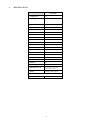
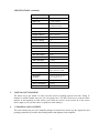
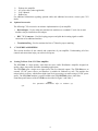
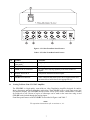
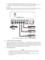
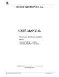
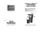
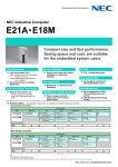
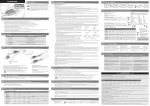
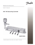
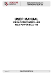
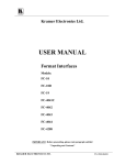
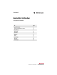
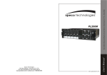
CVG-50V
1x5 Video Distribution Amplifier
CVG-50A
1x5 Audio Distribution Amplifier
USER MANUAL
CONTENTS
1. INTRODUCTION
3
1.1
A Word On Distribution Amplifiers
3
1.2
Factors Affecting Quality of Results
3
2. SPECIFICATIONS
4
3. HOW DO I GET STARTED?
5
4. UNPACKING AND CONTENTS
5
4.1
6
Optional Accessories
5. CVG SERIES AMPLIFIERS
6
5.1
Getting To Know Your CVG-50A Amplifier
6
5.2
Getting To Know Your CVG-50V Amplifier
7
6. INSTALLATION
8
7. CONNECTING TO VIDEO DEVICES
8
8. CONNECTING TO AUDIO DEVICES
9
9. USING THE CVG VIDEO/AUDIO AMPLIFIERS
9
9.1
Powering On The Amplifier
9
9.2
Looping
9
9.3
Coupling
9
9.4
Installing an Amplifier In a Mixed AC/DC Video/Audio System
9
10. TAKING CARE OF YOUR AMPLIFIER
10
11. TROUBLESHOOTING
10
11.1
Power And Indicators
111
11.2
Audio Signal
11
11.3
Video Signal
12
FIGURES
FIGURE 1: CVG-50A FRONT/REAR PANEL FEATURES
FIGURE 2: CVG-50V FRONT/REAR PANEL FEATURES
FIGURE 3: INSTALLING AN AMPLIFIER IN A MIXED AC/DC VIDEO/AUDIO SYSTEM
7
8
10
TABLES
TABLE 1: CVG-50A FRONT/REAR PANEL FEATURES
TABLE 2: CVG-50V FRONT/REAR PANEL FEATURES
7
8
1
1.
INTRODUCTION
Congratulations on purchasing your Video/Audio Distribution Amplifiers. This user manual describes
the following products:
CVG-50A
CVG-50ACVG-50V-
1.1
CVG-50V
1:5 Audio Distributor
1:5 Video Distributor
A Word On Distribution Amplifiers
Distribution amplifiers are used to distribute one source to several acceptors for simultaneous
recording or monitoring of one source, with no discernible signal degradation. They vary in the
number of inputs, looping capability, programming capability, number of outputs, operating format,
bandwidth and input/output coupling. A good quality distribution amplifier amplifies the incoming
signal, pre-compensates the signal for potential losses (resulting from the use of long cables, noisy
source, etc.) and generates several identical buffered and amplified outputs.
1.2
Factors Affecting Quality of Results
There are many factors affecting the quality of results when signals are transmitted from a source to an
acceptor:
Connection cables - Low quality cables are susceptible to interference; they degrade signal quality
due to poor matching and cause elevated noise levels. They should therefore be of the best quality.
Sockets and connectors of the sources and acceptors - So often ignored, they should be of highest
quality, since "Zero Ohm" connection resistance is the target. Sockets and connectors also must match
the required impedance (75 ohms in video). Cheap, low quality connectors tend to rust, thus causing
flaws in the signal path.
Amplifying circuitry - Must have quality performance when the desired end result is high linearity,
low distortion and low noise operation.
Distance between sources and acceptors - Plays a major role in the final result. For long distances
(over 15 meters) between sources and acceptors, special measures should be taken in order to avoid
cable losses. These include using higher quality cables or adding line amplifiers.
Interference from neighboring electrical appliances - These can have an adverse effect on signal
quality. Balanced audio lines are less prone to interference, but unbalanced audio should be installed
far from any mains power cables, electric motors, transmitters, etc. even when the cables are shielded.
3
2.
SPECIFICATIONS
CVG-50A
Configuration
1:5
Input Type
1 stereo audio
Input Connections
RCA
Input Level
Looping +4dbm/50kohm
Output Type
5 stereo audio
Output Connector
RCA connectors
Output Level
+4dBm/100ohm
Output Coupling
AC
S/N Ratio
83db unweighted
Audio Bandwidth
50khz, -3db
Video Bandwidth
NA
Max audio Output
25Vpp
Max video Output
NA
Differential Gain
NA
Differential Phase
NA
Audio THD+N
<0.018%
Second harmonic
0.003%
K-Factor
NA
SDI eff. Range
NA
Dimensions (W, D, H)
16.5cm x 12cm x 4.5cm
6.5" x 4.72" x 1.77"
Weight
0.62Kg (1.4lbs) Approx.
Power consumption
0.78VA
Power Source
12VDC, 40mA
4
SPECIFICATIONS (continued)
CVG-50V
3.
Configuration
1:5
Input Type
1 video, looping
Input Connections
BNC connector with
termination switch
Input Level
1Vpp/75ohm
Output Type
5 video
Output Connector
BNC connectors
Output Level
1Vpp/75ohm
Output Coupling
AC
S/N Ratio
73db
Audio Bandwidth
NA
Video Bandwidth
480MHz -3dB
Max audio Output
NA
Max video Output
2Vpp
Differential Gain
0.05%
Differential Phase
0.12Deg
Audio THD+N
NA
K-Factor
<0.05%
Level Controls
Gain Range = -0.8 to 1.9db
EQ. control: 0 to 3.2db
Gain Range
-0.8 to 1.9dB
Dimensions
(W, D, H)
16.5cm x 12cm x 4.5cm
6.5" x 4.72" x 1.77"
Weight
0.62Kg (1.4lbs.)
Power consumption
0.48VA
Power Source
12VDC, 40mA
HOW DO I GET STARTED?
The fastest way to get started is to take your time and do everything right the first time. Taking 15
minutes to read the manual may save you a few hours later. You don’t even have to read the whole
manual. At the beginning of each section, you’ll find an overview of the section. So if the section
doesn’t apply to you, you don’t have to spend your time reading it.
4.
UNPACKING AND CONTENTS
The items contained in your CVG amplifier package are listed below. Please save the original box and
packaging materials for possible future transportation and shipment of the amplifier.
5
Desktop size amplifier
AC power cable (where applicable)
User’s Manual
Rubber feet
For additional information regarding optional cables and additional accessories, contact your CVG
dealer.
4.1
Optional Accessories
The following CVG accessories can enhance implementation of your amplifier.
Rack Adapter - Used to adapt non-standard size machines to a standard 1U rack. One or more
machines may be installed on each adapter.
BNC "Y" Connector - Used for looping purposes and splits the incoming signal to enable
connection of an additional machine.
Termination Plug - Used to terminate the line to 75ohm for proper matching..
5.
CVG SERIES AMPLIFIERS
This section describes all the controls and connections of your amplifier. Understanding all of the
controls and connections helps you realize its full power.
5.1
Getting To Know Your CVG-50A Amplifier
The CVG-50A is a high quality, state-of-the-art stereo audio Distribution Amplifier designed for
studios, shops, showrooms and other demanding applications.
The CVG-50A splits a single stereo input source into five identical outputs. The CVG-50A uses an
external 12V DC power source, and therefore is suitable for fieldwork as well. The machine has
unique built-in circuitry, which allows high signal level processing even while using a 12VDC power
source. The CVG-50A machine is a perfect match to the CVG-50V/50S video/s-video DAs.
Front/Rear panel features of the CVG-50A are described in Figure 3 and Table 3.
NOTE
For operation instructions refer to sections 9.1,
9.2.
6
Figure 1: CVG-50A Front/Rear Panel Features
Table 1: CVG-50A Front/Rear Panel Features
No.
1.
2.
3.
4.
5.
5.2
Feature
Function
Illuminated power switch (on
front panel)
IN (L, R) RCA connectors
LOOP in RCA connectors
Supplies power to the unit.
OUTPUTS 1-5 RCA
connectors
12VDC feed connector
Audio input.
Provides audio looping capability to increase number of
outputs.
5 amplified and buffered audio outputs.
A DC connector that allows power to be supplied to the unit.
An internal fuse holder houses the appropriate fuse.
Getting To Know Your CVG-50V Amplifier
The CVG-50V is a high quality, state-of-the-art, video Distribution Amplifier designed for studios,
shops, showrooms and other demanding applications. The CVG-50V splits a single input source into
five identical outputs. The CVG-50V uses an external 12VDC power source, and therefore is suitable
for fieldwork as well. Dozens of copies of videotapes can be made at the same time using several
CVG-50V units chained through the looping inputs.
Front/Rear panel features of the CVG-50V are described in Figure 6 and Table 7.
NOTE
For operation instructions refer to sections 9.1, 9.2.
7
Figure 2: CVG-50V Front/Rear Panel Features
Table 2: CVG-50V Front/Rear Panel Features
No.
Feature
Function
1.
Supplies power to the unit.
2.
Illuminated power switch (on
front panel)
Hi-Z/75 Ohms switch
3.
4.
INPUT BNC connector
LOOP BNC connector
5.
OUTPUTS 1- 5 BNC
connectors
12VDC feed connector
6.
6.
Selects "75ohm" or "HI-z" impedance (pressed="75ohm").
For looping select "Hi-z".
Video input
Provides audio looping capability to increase number of
outputs.
5 amplified and buffered video outputs.
A DC connector that allows power to be supplied to the unit.
An internal fuse holder houses the appropriate fuse.
INSTALLATION
The amplifier is provided with four rubber feet packed in a separate bag. Affix the feet to the unit,
place it on a table away from heat generating sources and make the required connections. Use a rack
adapter in case a rack installation is required (see section 4.1 "Rack Adapters"), in which case do not
attach the feet.
7.
CONNECTING TO VIDEO DEVICES
Video sources and output devices (such as amplifiers or recorders) may be connected to the amplifier
through the BNC connectors (CVG-50V models) located at the back of the machine. Please keep in
mind that the output signal format will match that of the input signal format. All signal connections
that use more than one cable interconnecting between devices should be of equal length.
8
8.
CONNECTING TO AUDIO DEVICES
Audio sources and output devices (such as amplifiers or recorders) may be connected to the amplifier
through the RCA type connectors (CVG-5A) located at the back of the machines.
9.
USING THE CVG VIDEO/AUDIO AMPLIFIERS
9.1
Powering On The Amplifier
NOTES
1.
Amplifier should only be powered on after all connections are completed and all source
devices have been powered on. Do not attempt to connect or disconnect any video, audio or
control signals to the amplifier while it is powered on!
2.
The socket-outlet should be near the equipment and should be easily accessible. To fully
disconnect equipment, remove power cord from its socket.
1) Press the toggle switch on the far-left front panel to the up position. In the up position, the toggle
switch glows, and the active input button illuminates as well.
2) Operate the acceptors.
9.2
Looping
The looping function enables the operator to extend the number of outputs per input. The following
example describes looping performed by using 3 amplifiers with one input and 5 outputs each: A video
signal reaches input of amplifier No. 1. From looping connector of amplifier No. 1 a cable is connected
to input socket of amplifier No. 2. The loop output of amplifier No. 2 is connected to the input socket
of amplifier No. 3. In this way the input signal is divided into 15 separate output signals. The operator
must always switch to "Hi-z" the termination switch of all the amplifiers but the last. The last
amplifier’s termination switch should always be at "75ohm" to maintain well-matched video line (of
75ohm impedance) from first to last amplifier. Note that if looping function is not used, the
termination switch should be set to "75 ohm".
9.3
Coupling
The coupling function enables the operator to determine whether the incoming video signal is DC or
AC coupled. When DC coupling is selected and proper standard video signal is applied to the
amplifier’s input, the output signal is equal to the input signal. When AC coupling is selected, DC
components of the incoming signal are removed. DC coupling is always preferable since AC coupling
might cause some linearity distortions in low and high frequencies (due to non-ideal behavior of
capacitors). A problem may arise when the incoming signal is riding on a DC offset especially when
the acceptors are highly effected by deviation of DC offsets (A to D converters for example), which in
turn results in a distorted picture.
9.4
Installing an Amplifier In a Mixed AC/DC Video/Audio System
Video accessories use two basic forms of connection to sources and acceptors: AC coupled or DC
coupled. Each form has its own advantages. DC coupling provides a non-distorted signal, transferring
accurately the DC contents of input signals to the outputs. AC coupling suffers from problems related
to bad quality, low frequency response and the "breathing" effect. However, AC coupling isolates the
acceptors from an erroneous DC level sometimes found in video sources. If a video acceptor is too
sensitive to the DC content transferred to it via the DA from the source, AC coupling is preferred. AC
coupling may be initiated by either using a "AC/DC" coupling switch available on some of the video
DAs, or adding DC-removing components externally.
Perform the following steps (if necessary):
1) Connect the video source to the DA.
9
2) Add external coupling capacitors to each output of the DA that needs AC coupling.
3) Connect the acceptors to the outputs of the DA. Connect the DC coupled acceptors directly and
connect the AC coupled acceptors via back to back connected 1000µF/25V capacitors.
A useful tip:
The capacitor may be "stitched" on the coaxial cable directly, by carefully separating the shield from
the signal leading conductor, cutting this conductor and connecting the capacitor serially.
Figure 3: Installing an Amplifier in a Mixed AC/DC Video/Audio System
10.
TAKING CARE OF YOUR AMPLIFIER
Do not locate your amplifier in an environment where it is susceptible to dust or moisture. These may
damage the electronics, and cause erratic operation or failure. Do not locate your amplifier where
temperature and humidity may be excessive. Do not clean your amplifier with abrasives or strong
cleaners. Doing so may remove or damage the finish, or may allow moisture to build up. Take care not
to allow dust or particles to build up inside unused or open connectors.
11.
TROUBLESHOOTING
NOTES
1. Please note that if the output signal is disturbed or interrupted by very strong external
electromagnetic interference, it should return and stabilize when such interference ends. If
not, turn the power switch off and on again to reset the machine.
2. If the recommended actions still do not result in satisfactory operation, please consult
your CVG Dealer.
10
11.1 Power And Indicators
Problem
No Power
Remedy
1.
2.
Confirm that the rocker switch is in the “ON” position, and that the
red LAMP/LED is illuminated.
Confirm that power connections are secured at the amplifier and at the
receptacle. Make sure the receptacle is active, outputting the proper
mains voltage.
For models CVG-50A, CVG-50V perform the following:
1.
2.
3.
Using a Philips screwdriver, remove screws attaching the machine's
cover.
Locate fuse holder located inside your amplifier. Confirm that the fuse
is good by looking for the wire connected between the ends of the
fuse. If this wire is broken, replace fuse with another, with the same
rating.
Install cover by tightening the Philips screws.
.
11.2 Audio Signal
(CVG-50A only)
Problem
No audio at the Output
Device, Regardless of
Input Selected
Remedy
1.
2.
Audio level is too low
1.
2.
Confirm that your sources and output device are powered on and
connected properly. audio signals connected to the input of your
amplifier should be properly wired to the output of your source. audio
signals connected to the output of your amplifier should be properly
wired to the input of your amplifier or recorder.
Confirm that any other amplifiers in the signal path have the proper
input and/or output selected. Pay special attention to input amplifiers
that may be built into your amplifier or recording device.
Confirm that the connecting cables are of high quality and properly
built. Take special care in noting the wiring configuration of balanced
to unbalanced cables.
Check level controls located on your source input device or output
device.
11
11.3 Video Signal
(CVG-50V only)
Problem
No video at the
output device,
regardless of input
selected
Video level is too
high or too low
Noise bars "roll" up
or down in the output
image
or:
Low frequency hum
in the output signal
Remedy
1.
Confirm that your sources and output device are powered on and
connected properly. Video signals connected to the input of your
amplifier should be of an identical signal format at the output of your
source. Video signals at the output of your amplifier should be of an
identical signal format as at the input of your display or recorder.
2. Confirm that any other amplifiers in the signal path have the proper input
and/or output selected.
1. The amplifiers in this manual (except for the CVG-2N) have termination
switches on each input. Verify that the video line is well interfaced
through 75ohm impedance; otherwise it results in a video level that is too
high or too low. Check if looping is used and if termination switch is in
the proper position for this state.
2. Confirm that the connecting cables are of high quality, properly built and
terminated with 75ohm BNC connectors. Check level controls located on
your source input device or output device.
Hum bars (ground loop) are caused by a difference in the ground potential of
any two or more devices connected to your signal path. This difference is
compensated by passing that voltage difference through any available
interconnection, including your video cables.
WARNING!
Do not disconnect the ground from any piece of
video equipment in your signal path!
Check the following to remove hum bars:
1.
2.
3.
Confirm that all interconnected equipment is connected to the same phase
of power.
Remove equipment connected to this phase that may be introducing
noise, such as motors, generators, etc.
Disconnect all cables and reconnect them one at a time until ground loop
reappears. Disconnect the affected cable and replace, or insert an isolation
device (opto isolator or transformer) in the signal path.
For Technical Support, contact us at:
Comprehensive Video Group
55 Ruta Court
South Hackensack, NJ 07606
800-526-0242
e-mail:[email protected]
www.comprehensivevideo.com
12