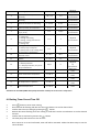
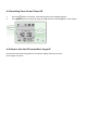
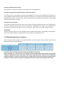
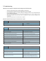
1
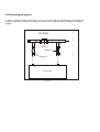
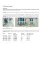
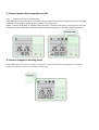
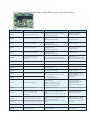
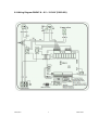
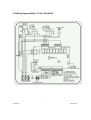
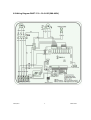
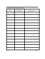
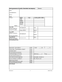
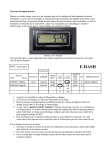
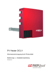
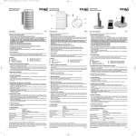
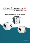
SWIMMING POOL
HEAT PUMP
Model ZWPA / ZWPT
INSTALLATION AND USER’S MANUAL
05022014RM
This manual is valid for all ZWPA / ZWPA swimming pool heat pumps.
Dear customer,
In order to have more ease of the remote control of your pool heat pump, we advise you to place
the LED display with the mounting bracket by using the extension cable (11 meter) in a shady
place. For example next to the pool control.
Beste klant,
Om nog meer bedieningsgemak van de afstandsbediening van uw zwembadwarmtepomp te
hebben, adviseren wij u om de LED display met de bijgeleverde verlengkabel (11 meter) met de
montagehouder te plaatsen op een schaduwrijke plaats. Bijvoorbeeld naast de pool control.
Sehr geehrter Kunde,
Um mehr Leichtigkeit der Fernbedienung Ihres Pool Wärmepumpe zu haben, empfehlen wir, die
LED-Anzeige mit der Halterung mit dem mitgelieferten Verlängerungskabel (11 Meter), in einem
schattigen Ort platzieren. Zum Beispiel neben dem Pool Kontrolle.
Cher
client,
Afin d'avoir plus d'aisance de la télécommande de votre pompe à chaleur de piscine, nous vous
conseillons de placer l'écran LED avec le support de montage en utilisant le câble de rallonge (11
mètres) dans un endroit ombragé. Par exemple en regard de la commande de la piscine.
ZWEMBAD WARMTEPOMP
Dear customers, please read this instruction carefully before the installation and applicationof this
product, otherwise it may lead to damage to the instrument or operators as well asfinancial loss. When
you might need further information please contact your local distributor. With the gradual advancement
of science and technology, the product series and specifications will change as well, so you are invited to
keep up with the latest products. In reading this instruction, if you need any technical consultations,
contact your local distributor.
ATTENTION:
√
In selecting the heat pump water heater unit to install, check whether the corresponding power
supply agrees with the specifications for heat pump water heater unit power, For detail, refer to the
tag on the unit or the installation and operation instruction.
√
Make sure electricity leakage protection equipment is installed properly according to the
regulations and guidelines valid in your area. If you’re not sure please contact a professional
electrician.
√
The water heater unit must be reliably ground. It is forbidden to use this unit with no reliable
grounding. It is forbidden to connect the ground wire to the zeroline or running water pipes.
√
In wire connection, the electrician must refer to the connection map and wiring diagrams, which can
be found in the back of this manual.
√
For safety, do not change or repair the heat pump water heater unit without permission. If
necessary to make any adjustments you should always contact your local distributor before
adjustment.
√
It is forbidden to insert any tools into the heat pump unit in case it may touch the fan to damage the
unit or lead to accidents (especially for children).
√
Hot water with a temperature of more than 52℃ can lead to burns. Therefore, only when the hot
water in water tank combines with cold water can it be used.
√
Do not use the water heater unit with the grid or plate work removed in case it may lead to any
accidents or abnormal operation of the unit.
√
If the unit is soaked by water, contact immediately with our factory or its service department. The
unit can be reused only after check and solution by the technical staff.
√
Unqualified technical staff are not allowed to adjust the switches, valves or controllers in the unit.
CONTENTS:
Description
Chapter 1: General Information
1.1 Performance and features
1.2 Working principles
1.3 Technical specifications of the heat pump
Page
6
6
7
Chapter 2: Installation
2.1 Installation of the swimming pool heat pump
2.2 Dimensions of the swimming pool heat pump (9.5 – 21.0 kW)
2.3 Dimensions of the swimming pool heat pump (26 kW)
2.4 Location of the heat pump
2.5 Distance from the pool
2.6 Installation of the check-valve
2.7 Pool system set-up
2.8 Installing the pipings and by-pass
2.9 Electrical Hook-Up
9
11
11
12
13
13
14
15
16
Chapter 3: Start-up
3.1 Starting up the heat pump
3.2 On/off release of the heat pump
3.3 Balancing the flow with the by-pass
17
18
19
Chapter 4: Controlling the heat pump
4.1 Operating the LED controller
4.2 Power on the heat pump
4.3 How to set the working mode
4.4 How to set the desired water temperature
4.5 How to check and set the parameter values
4.6 How to set the clock
4.7 Parameter table
4.8 How to set the timer on/off function
4.9 How to cancel the timer settings
4.10 How to (de)block the controller
20
21
21
22
22
22
23
24
24
24
Chapter 5: Protection systems
5.1 Built-in protections of the heat pump
5.2 Swimming pool water chemistry
25
26
Chapter 6: Maintenance and inspection
6.1 Winterizing the swimming pool heat pump
6.2 Restarting the heat pump after winter
6.3 Check-up
6.4 Maintenance
27
27
28
28
Chapter 7: Troubleshooting
7.1 Troubleshooting
7.2 Failure codes table
29
31
Chapter 8: Wiring Diagrams
8.1/8.2 Wiring diagrams of 1-phase 220/240V units
8.3/8.4 Wiring diagrams of 3-phase 380/400V units
33
35
1.1 Performance and features
√
With a CO P value up to 5.0 our heat pumps are very efficient w hen trans ferring heat from the air
to the s w imming pool w ater. You can s ave as much as 80% of cos t compared to an electrical
heater.
√
√
The heat exchanger is made of PVC and Titanium tube, which can withstand and prolong exposure
to swimming pool water.
The unit is very easy to operate: simply switch it on and set the desired pool water temperature.
The system includes a micro-computer controller, allowing all operation parameters to be set.
Operation status can be displayed on the controller with LED display.
1.2 Working principles
√
√
√
√
√
Heat pumps utilize the sun's free heat by collecting and abs orbing energy from the outs ide air. This energy
is then compressed and transferred to the pool w ater. Your exis ting w ater pump circulates the water
through the heater, usually next to the pool equipment, and the water warms up. The heat pump timer
could be set to operate during daylight hours, for example, usually 9am to 5pm.
The unit contains a fan that draws in outside air and directs it over the surface of the evaporator (energy
collector).The liquid refrigerant within the EVAPORATOR coil absorbs the heat from the outside air becomes
a gas.
The warm gas in the coil passes through the COMPRESSOR concentrating and increas ing the heat to form a
very hot gas which then passes to the CONDENSER (water heat exchanger).It is here that the heat exchange
occurs as the hot gas gives off heat to the cool swimming pool water circulating through the coil.
The pool water becomes warmer, and the hot gas cooling as it flow s through the CO N D EN S ER coilreturns to its liquid form and, after passing on through the CAPILLARY TUBE, the whole process begins
again.
The state of the heat pump technology can efficiently collect heat from the outside air down to the 7℃ to 10
range. For tropic and subtropical climates, this means that the pool can be maintained at 26℃ to 32℃.
1.3 Technical specifications of the swimming pool heat pump (220-240V)
•
•
If differences are found between the information in this manual and on the name plate of the pump, always follow the data on the
product itself.
1) Sound pressure dB(A) measured at a distance of 10 meter.
1.3 Technical specifications of the swimming pool heat pump (380-415V)
•
•
If differences are found between the information in this manual and on the name plate of the pump, always follow the data on the
product itself.
1) Sound pressure dB(A) measured at a distance of 10 meter.
2.1 Installation of the swimming pool heat pump
Remark:
The delivery of the pool heat pump only includes the swimming pool heat pump, other necessary parts
must be purchased separately.
Attention:
Please follow these steps carefully when installing the heat pump:
√
√
√
√
The heat pump must always be placed on a firm, flat surface. Always use vibration dampers to
avoid vibration and unnecessary noise production.
The heat pump must always remain in upright position (even during transport). It is recommended
that the heat pump stands steady for at least 24 hours after transport or movement before you
turn on the system.
The heat pump may only be serviced by an authorized installer.
Always use original parts! The use of other parts than the original ones, may lead to efficiency
problems and/or damage the unit.
Warranty is only applicable when:
√
√
√
√
√
√
√
The heat pump is installed in accordance with the guidelines in this manual.
The electrical supply and security components such as circuit breaker and fuses meet the
requirements in your local area’s guidelines.
The installation meets the hydronic conditions as stated in the technical specifications on page 5.
Placement of the heat pump is in accordance with the terms and conditions on page 8/9
The heat pump is switched in the right way
The heat pump is serviced by a certified technician on a yearly basis
The unit is not exposed to frost
2.2 Dimensions of the swimming pool heat pump (7.8 – 21.0 kW)
Model
ZWPA7.8H1F
ZWPA9.5H1F
ZWPA12.5H1F
ZWPA17.0H1F
ZWPT17.0H3P
ZWPT21.0H3P
A
584
594
594
722
711
958
B
554
564
564
694
694
944
C
85
85
85
85
85
85
The above dimensions are given in mm.
D
250
300
300
400
400
500
E
968
1044
1044
1108
1108
1078
F
360
370
370
416
416
446
G
313
340
340
386
386
420
2.3 Dimensions of the swimming pool heat pump (26 kW)
Model
ZWPT26.0H3P
A
1258
B
1244
C
85
The above dimensions are given in mm..
D
620
E
1108
F
446
G
420
2.4 Location of the swimming pool heat pump
The unit will perform well on any location provided three factors are present:
1. Fresh air supply
2. Electricity
3. Swimming pool filter piping
The unit may be installed virtually anywhere outdoors providing minimum distance requirements are met
with respect to other objects (see diagram below).For indoor pools please consult your installer. If the unit
is placed in a windy area, no problems occur with e.g. the pilot light, as opposed to what is often the case
with gas heaters.
Attention:
Do not place the unit in an enclosed area with a limited air volume where the unit's discharged air will be
re-circulated or near shrubs that could block the air inlet. These locations deny the unit a continuous fresh
air supply, which reduces its efficiency and may prevent adequate heat yield. See diagram below for
minimum required distances.
2.5 Distance from the pool
Normally, the pool heat pump is installed within a 7.5 meter radius of the pool. The greater the distance
from the pool, the greater the heat los s from the piping. S ince the piping is buried for the mos t part, heat
loss is minimal for distances of up to 30 meters (15 meters to and from the pump= 30 meters total), unless
the soil is wet or the water level is high. Heat loss per 30 meters could roughly be estimated at 0.6 kw hour (2000 BTU ) for every 5 ℃ temperature difference betw een the pool w ater and the s oil
surrounding the pipe, which translates to an operation time increase of 3-5%.
2.6 Installation of the check-valve
When using automatic chlorine and PH dosage systems, it is of uttermost importance to protect the heat
pump from high concentrations of these chemicals that could corrode the heat exchanger. Therefore, such
systems should add the chemicals in the conduits located downstream of the heat pump and it is
recommended to install a check-valve in order to prevent backflow when there is no water circulation.
Damage to the heat pump caused by disregarding any of these recommendations will invalidate the
warranty.
2.7 Pool system set-up
Ensure that the heat pump is installed above the pool level. Please make sure that it is possible for the
water to run out of the heat pump automatically when the circulation pump is switched off, because then
the flow switch will turn of the heat pump. When the heat pump continues running without any flow it
could cause enduring errors and or damage you heat pump.
2.8 Connecting the by-pass
In order to regulate the heat pump’s water circuit, you must provide a by-pass between the incoming and
outgoing connections. Therefore the piping must feature three regulation-valves according to the below
diagram.
T
F
BY-PASS
r
o
o
m
p
o
o
f
Valve 1
Valve 2
l
i
l
t
e
Valve 3
r
OUT
IN
HEATPUMP
Figure 1-8
2.9 Electrical hook-up
IMPORTANT!
Although the heat pump is electrically isolated from the rest of the unit, this only prevents the passage of electricity to or from the
pool water. Grounding the unit is still required to protect yourself from short circuits inside the unit. Please contact a certified
electrician to make sure your heat pump is grounded correctly..
For horizontal models (VBK / ZWPT / ZWPA) the electrical connection area is located behind the cover on the right side next to the
fan opening.
Connect the electrical wires with the terminal block labelled “Power Supply”. Next to this connection, there is a second terminal
block labelled “Water Pump”,to which the filter pump (max . 5A/240V) can be connected. This connection makes it possible to
control filter pump operation with the heat pump. See further at Parameter setting table (Parameter 9) for the different
possibilities.
Remarks for models with 3 phases:
for models with 3 phases, switching 2 phases may cause in inversion in the rotational direction of electrical motors, which could
damage the unit. Therefore, a protection device has been built in, which will interrupt the circuit if the connection has not been
performed correctly.
Model
Voltage (V)
ZWPA-7.8H1F
ZWPA-9.5H1F
ZWPA-12.5H1F
ZWPA-17.0H1F
ZWPT-17.0H3P
ZWPT-21.0H3P
ZWPT-26.0H3P
220-240
220-240
220-240
220-240
3 x 380
3 x 380
3 x 380
Fuse (A)
Slow C-curve
16 traag (C)
16 traag (C)
20 traag (C)
25 traag (C)
16 traag (C)
16 traag (C)
16 traag (C)
Nominal
Current(A)
7,9
9,7
12,7
14,5
6,4
8,0
9,8
2
Cable diameter (mm )
Max. length of 15 m.
2x2,5 + 2,5
2x2,5 + 2,5
2x2,5 + 2,5
2x4,0 + 2,5
4x2,5 + 2,5
4x2,5 + 2,5
4x2,5 + 2,5
3.1 Starting up the heat pump (first-time)
Attention!
In order for the unit to heat the pool (or spa), the filter pump must be running so that the water can
circulate through the heat pump. Without this circulation, the heat pump will not start.
When all connections have been made and checked, you should follow these steps:
√
Turn on the filter pump. Check for leaks and verify flow to and from the pool.
√
Turn on the electrical power supply to the unit, then press the ON/ OFF key on the electronic
control panel. The unit should start when the time delay period has lapsed.
√
When the unit has been running for a couple of minutes, check if the air leaving the unit is cooler.
√
Check the performance of the flow switch as follows: with the unit running, turn the filter pump off.
The unit should also switch off automatically. If not, the flow switch must be readjusted.
√
All the unit and filter pump to run 24 hours a day until the desired pool water temperature is
reached. When the set temperature is reached, the unit switches itself off. The unit will now
automatically restart (as long as your filter pump is running) when the temperature of the pool
water experiences a drop of more than 1℃ below the set temperature.
Depending on the starting temperature of the pool water and the air temperature, it can take several days
for the water to reach the desired temperature. Covering the pool can drastically reduced this period.
Water Flow Switch
The unit is equipped with a flow switch that is switched on when enough water has
flowed through the unit and that is switched off when the water flow becomes too low. (For example when
the filter pump is switched off).
Time delay
The unit is equipped with a built-in 3-minute s tart delay included to protect electrical
components and contacts. After this time delay, the unit will automatically be restarted. Even a brief
interruption of the pow er supply will activate the s tart delay and prevent the unit from s tarting
immediately. Additional interruptions of the power supply during the delay period will have no effect on
the 3-minute countdown.
Condensation
When the swimming pool water is being heated by the heat pump, the incoming air is cooled down quite a
bit, which can cause condensation on the fins of the evaporator. Condensed volumes can attain several
liters per hour under high atmospheric humidity. Sometimes, this is wrongfully interpreted as a water leak.
4.1 Controlling the heat pump with the LED controller
When heat pump is supplied with power, controller will display with full screen, shows that it is already
connected. If connection fails in 10 seconds, please check connections between communication cable and
control display, or replace with another control display.
Button functions:
Turns the heat pump on or off
Timer button to set timer on and timer off
Gives access to the parameter list and is used to confirm settings
To set the desired working mode: heating, cooling or auto mode
To decrease
or increase
value
LED display icon defitioning:
heating icon, showing heat pump is in heating mode
cooling icon, showing heat pump is in cooling mode
auto icon, showing heat pump is in auto mode
compressor icon, showing compressor status
water pump icon, showing water pump status
fan icon, showing fan status
defrost icon, showing defrost status
four way valve icon, showing four way valve status
electric heater icon, showing if external electric heater is activated or not.
electric heater running icon, showing electric heater is running or not
alarm icon, showing system alarm
fan speed icon, showing high (3), medium(2) and low(1) fan speed
key pad lock icon, showing buttons on the control display are locked.
Remark:
1. Heat pump is not equipped with electric heater internally, only provides terminal for external connection.
2. Fan speed is automatically controlled by ambient temperature, not manually.
4.2 How to power the heat pump on or off?
Press
button to switch on the heat pump.
Once the heat pump is powered on all related running component icons will be lightened as well as POWER
displayed in the middle of display to show system is in running status.
Figure 2-2 shows heat pump in standby status and figure 2-3 shows heat pump in running status. The left
temperature shows flow water temperature while the right temperature is the return water temperature.
4.3 How to change the working mode
Press MODE button to select auto, heating or cooling mode, related indicator icon will be lightened as a symbol to
show the heat pump is in either auto, heating or cooling mode.
.
4.4 Adjust desired water temperature
1.
First select the desired mode; auto, heating or cooling.
2. Then use the arrow buttons to increase or decrease the set value. The LED display will show the set value.
4.5 How to check and set the parameters
1.
Press “MENU” button for 5 seconds. The Parameter number and value will start flashing together on the LED
display.
2. Use the arrow buttons to navigate to the required parameter number.
3. Press the “MENU” button to choose the required parameter. The parameter number stays fixed, while the
value will continue to flash.
4. Use the arrow buttons to set the desired value for the chosen parameter. You can press the MENU button to
confirm the settings. Without any further movement on the display buttons in 5 seconds i twill return to the
main interface automatically.
ATTENTION!
You can always enter the parameter list and check the values, but the set values can only be changed when the heat
pump is in standby status.
4.6 Setting the time
1.
2.
3.
4.
5.
6.
Press MENU button in a quick stop to activate time setting
The hour numbers start flashing, adjust them with the arrow buttons
Press MENU button to confirm the hour setting
The minute numbers start flashing, adjust them by using the arrow buttons
Press MENU button to confirm the minutes setting
The LED display will return to the main interface
4.7 Parameter Table
Parameter
0
1
Omschrijving
Desired water temperature in
cooling mode
Desired water temperature in
heating mode
Range
Default
8 – 37 °C
28 °C
5 – 40 °C
28 °C
Remark
End User
(page. 20)
End User
(page. 20)
2
3
4
Defrosting cycle
Coil temperature set point to start
defrosting
Coil temperature set point to stop
defrosting
30 – 90 min
45 min
-30 – 0 °C
-7 °C
2 – 30 °C
13 °C
Adjusted
by Technicians
Adjusted
by Technicians
Adjusted
by Technicians
Adjusted
by Technicians
Adjusted
by Technicians
Adjusted
by Technicians
5
Maximum duration for defrosting
1 – 15 min
8 min
6
System quantity of compressors
1–2
1
0–1
1 (yes)
0–3
1
Adjusted
by Technicians
0–1
0
Adjusted
by Technicians
8 – 40 °C
40 °C
1 – 10 °C
2 °C
0/1/2
0
7
8
9
10
Restart after power failure
(1=yes, 0=no)
Mode lock:
0 = cooling only
1 = heating and cooling
2 = heating, cooling and external
electrical heatern
3 = heating only
Working mode of water pump:
0 = water pump is always on
1 = water pump is only running when
the heat pump is switched on
Desired water temperature in
automatic mode
11
Hysteria
12
Low pressure switch detection:
0 = default protection
1-2 = delayed protection, only to be
set by manufacturer
A
Actual inlet water temperature
-9 – 99 °C
B
Actual outlet water temperature
-9 – 99 °C
C
Coil temperature in system 1
-9 – 99 °C
D
Coil temperature in system 2
-9 – 99 °C
E
Ambient temperature
-9 – 99 °C
Adjusted
by Technicians
Adjusted
by Technicians
Adjusted
by
manufacturer
Measured
value
Measured
value
Measured
value
Measured
value
Measured
value
Attention! For the ZWPA/ZWPT heat pumps Parameter 6 always has to be set to 1 compressor!
4.8 Setting Timer On and Time Off
√
√
Press
button to enter timer setting
Hour data will be flashing with ON. Use the arrow buttons to set the desired hour.
√
√
Confirm the Timer On setting by pressing the
button.
Minute data starts flashing once hour setting is confirmed. Use the arrow buttons to set the desired
minutes.
Confirm the set minutes by pressint the
button
The heat pump will switch on at the set time
√
√
Once Timer On is set and confirmed, Timer Off will be activated. Follow the above steps to set the
Timer Off time.
4.9 Cancelling Timer On and Timer Off
√
√
Press the
button to activate, time and ON /OFF starts flashing together.
Press MENU button to cancel the timer and ON/ OFF icons will disappear on the display.
4.10 How to lock the LED controller’s key pad?
Press both arrow buttons together for 5 seconds, display will show lock icon.
Do this again to unlock.
5.1 Protection systems
Water flow switch
Equipped w ith flow s w itch the heat pump w ill not w ork w hen the filter pump is not w orking (and the
water is not circulating). This system prevents the heat pump from heating only the water present in the
heat pump itself. The protection also stops the heat pump if water circulation is cut off or stopped.
Refrigerant gas high and low pressure protection
The high pressure protection makes sure the heat pump is not damaged in case of over pressurisation of
the gas. The low pressure protection emits a signal when refrigerant is escaping from the conduits and the
unit can not be kept running.
Overheating protection on the compressor
This protection protects the compressor from overheating.
Automatic defrost control
When the air is very humid and cold, ice can form on the evaporator. In that event, a thin layer of ice
appears that will grow increasingly bigger as long as the heat pump is running. When the temperature of
the evaporator has become too low, automatic defrost control will be activated, which will reverse the heat
pump cycle so that hot refrigerant gas is sent through the evaporator during a brief period of time to
defrost it.
Temperature difference between inflowing and outflowing water
During normal operation of the heat pump, the temperature difference between inflowing and outflowing
water will approximate 1 to 2℃.In the event that the pressure switch does not work and that the water
stops circulating, the temperature probe monitoring the outflowing water will always detect a rise in
temperature. As soon as the temperature difference between inflowing and outflowing water exceeds
13℃, the heat pump will be automatically turned off.
Low temperature cut-out
If, during cooling, the temperature of the outflowing water reaches 5℃ or drops below this temperature,
the heat pump will turn itself off until the water temperature reaches or exceeds 7℃ again.
Anti-frost protection during winter
This protection can only be activated if the heat pump is in STAND-BY status.
First anti-frost protection (switching external water filter pump)
If the filter pump is controlled by the heat pump (regardless of the value for parameter 9) and when the
water temperature lies between 2 and 4℃,and the air temperature is lower than 0℃,the filter pump will be
automatically turned on to prevent the water from freezing in the piping. This protection is deactivated
when the temperature rises again.
Second anti-frost protection
If the water temperature drops even more, that is, below 2℃ (during long frost periods), the heat pump will
also start running to heat the water until its temperature approximates 3℃.When this temperature is
reached, the heat pump will stop, but anti-frost protection will remain active until conditions change.
ATTENTION!
The first anti-frost protection is only available when the external water pump is switched by the heat pump.
If the external water pump is not operated by the heat pump it should always be on.
5.2 Swimming pool water chemistry
Special attention should be paid to the chemical balance of the pool water. The pool water values should
always stay within the following limits:
Important: failure to comply with these limits will invalidate the warranty.
Note: exceeding one or several limits can damage the heat pump beyond repair. Always install water
treatment equipment past the heat pump's water outlet, especially if the chemicals are automatically
added to the water. A check-valve should also be installed between the outlet of the heat pump and this
equipment in order to prevent products from flowing back into the heat pump if the filter pump stops.
6.1 Heat pump winterizing
Important: failure to take the necessary precautions for winterizing can damage the heat pump, which
will invalidate the warranty.
The heat pump, filter pump, filter and conduits must be protected in areas where the temperature can drop
below the freezing point, Evacuate all water from the heat pump as follows:
√
√
√
√
√
Interrupt the electrical power supply to the heat pump
Close the water supply to the heat pump
Completely close valves 2 and 3 of the by-pass
Disconnect the water inlet and outlet coupler fittings of the heat pump and let the water drain out
of the unit.
Loosely reattach water inlet and outlet coupler fittings to the heat pump in order to prevent dirt
from setting into the conduits.
6.2 Restarting the pump after winter
If you purged your heat pump for winterizing, you should undertake the following steps to restart it in
spring:
√
√
√
√
Check first if there is no dirt in the conduits and if there are no structural problems
Check if the water inlet and outlet coupler fittings are adequately fastened to the heat pump
Start the filter pump to start the water flow to the heat pump. Set the by-pass again
Reconnect the electrical power supply to the heat pump and turn it ON.
6.3 Check-up
Our heat pumps have been developed and built to last, that is, if they have been installed correctly and can
run under normal conditions . Regular check-ups are important if you w ant your heat pump to function
safely and efficiently for years on end.
√
Make for easy access to the service panel
√
Keep the area surrounding the heat pump free of contingent organic waste
√
Prune the vegetation near the heat pump so that there is enough free space around the pump
√
Remove contingent water sprinklers from the vicinity of the heat pump. They can damage the heat
pump.
√
Prevent rain from directly running off a roof onto the heat pump. Install proper drainage
√
Do not use the heat pump if it has been flooded. Immediately contact a qualified technician to
inspect the heat pump and repair it if should prove necessary
Condensation can occur when the heat pump is running. This condensation can flow away through an
opening in the base pan of the unit. The amount of condensation water will increase when atmospheric
humidity is high. Remove any dirt that could possibly hamper the evacuation of condensation. 10 to 20
litres of condensation water can be produced while the unit is running. If more condensation is produced,
stop the heat pump and wait for one hour before checking for leaks in the conduits.
Note: a quick way to verify that the water running through the condensation drain is indeed condensation,
is to shut off the unit and keep the pool pump running. If the water stops running out of the condensation
drain, it is condensation. AN EVEN QUICKER WAY is to TEST THE DRAIN WATER FOR CHLORINE. If no
chlorine is detected, the drain water is a result of condensation.
Also take care to leave air inlet and exhaust passages free. Prevent exhaust air from immediately reentering the unit through the inlet.
6.4 Maintenance
√
√
√
√
√
√
Check the water inlet and drainage often. The water and air inflow into the system should be
sufficient s o t h a t i t s p e r f o r m a n c e a n d r e l i a b i l i t y d o e s n o t g e t c o m p r o m i s e d
. Yo u s h o u l d c l e a n t h e p o o l f i l t e r regularly to avoid damage to the unit caused by
clogging of the filter
Theareaaroundtheunitshouldbespaciousandwellventilated.Cleant
h e s i d e s o f t h e h e a t p u m p regularly to maintain good heat exchange and to save energy
Check if all processes in the unit are operational and pay special attention to the operation perssure
of the refrigerant system
Check the power supply and cable connections regularly. Should the unit begin to function
abnormally or should you notice a smell from an electrical component, arrange fro timely repair or
replacement
You should als o purge the w ater if the unit w ill not w ork for an extended period of time
You s hould check all parts of the unit thoroughly and completely fill the s ys tem w ith w ater
before turning it on again afterwards.
7.1 Trouble shooting
Attention! Do not attempt to modify the internal configuration of the heat pump.
-
Keep your hands and hair clear of the fan blades to avoid injury.
Do not attempt to modify the internal configuration of the heat pump.
Do not attempt to adjus t or s ervice w ithout cons ulting your dealer or your professional pool
or air conditioning contractor
Read the entire installation and user manual before attempting to use, service or adjust the unit
Start the heat pump at least 24 hours after its installation in order to prevent damage to the
compressor
Switch off the power prior to maintenance or repairs.
Attention! Switch off the power prior to maintenance or repairs.
Problem:
the heat pump doesn't work
Observation:
the screen does not light up and the fan/compressor doesn't make a sound
Possible cause
Solution
No electrical power supply
Check power supply (wiring, fuses,… …… …)
Problem:
the heat pump works normally but there is no or insufficient heating
Observation:
The screen displays the temperature but no error codes
Possible cause
Solution
1. In sufficient capacity of the heat pump in proportion to the
size of the swimming pool
1. Install a larger sized model or an extra heat pump.
Cover the pool to limit heat loss
2. The compressor works but the fan doesn't
2. Check the electrical wiring of the fan. Replace the
condenser or the fan motor if necessary.
3. The fan works but the compressor doesn't
3. Check the electrical wiring of the compressor.
Replace the condenser or the compressor if necessary.
4. The heat pump has not been placed on an optimal location
4. Make for sufficient air circulation(see manual for
details)
5. Faulty temperature setting
6. By-pass not adjusted
7. Massive ice formation on the evaporator
8. Not enough refrigerant
5. Set the correct temperature
6. Have the by-pass readjusted by the installer
7. Have the settings for automatic defrost control
checked by the installer
8. Have the heat pump checked by a refrigeration
technician
Problem:
The heat pump works normally but the water is cooling down instead of heating up
Observation:
The screen displays the temperature but no error codes
Possible cause
1.The wrong mode has been selected
2. The controller is out of order
3. The 4-way valve is out of order
Solution
1.Verify the parameters, select the correct mode
2. Check the voltage in the electrical wiring to the
4-way valve. If no electric potential is measured,
replace the controller
3. Check the voltage in the electrical wiring to the
4-way valve. If electric potential is measured,
replace the coil. If the problem persists, have the
heat pump checked by a refrigeration technician
Problem:
the heat pump doesn't stop
Observation:
the screen displays the temperature but no error codes
Possible cause
Solution
1.Wrong setting of parameters
2. Pressure switch out of order
3. Electrical failure
1.Check the set parameters and adjust them if necessary
(settings just above the capacity of the heat pump)
2. Check operation of the pressure switch by turning
off the filter pump and restarting it. If the heat pump
doesn't react to this, the pressure switch must be
adjusted or replaced.
3. Contact your installer
Problem:
water leak
Observation:
there's an amount of water under the heat pump
Possible cause
Solution
1.Condensation due to atmospheric humidity
1.No action required
2.Water leak
2.Try to localize the leak and check for the presence
of chlorine in the water. If that is the case, the heat
pump must be temporarily replaced during repair.
Problem:
abnormal amount of ice formed on the evaporator
Observation:
the evaporator is for the most part covered in ice
Possible cause
1.Insufficient air inflow
2.High water temperature
3.Incorrect setting of automatic defrost control
4.The 4-way valve is out of order
5.Not enough refrigerant
Solution
1.Check the location of the heat pump and remove any
dirt that could be present on the evaporator
2.If the pool water is already quite hot (warmer than
29?),the probability of ice formation increases.
Lowering the set temperature is a possible option
3.Check the setting of the defrosting function together
with your installer.
4.Check the voltage in the electrical wiring to the 4
-way valve. If electric potential is measured, replace
the coil. If the problem persists, have the heat pump
checked by a refrigeration technician.
5.Have the heat pump checked by a refrigeration
technician.
5.3 Failure code table for plug-in type PCB single system (4 cables)
Wire controller
Protection/Failure
PP01/PP1
Inlet water temp. sensor failure
1. Check the connection of inlet water
sensor.
2. Check if the sensor is broken.
1. Reconnect the sensor.
2. Replace the sensor.
PP02/PP2
Outlet water temp. sensor failure
1. Check the connection of outlet water
sensor.
2. Check if the sensor is broken.
1. Reconnect the sensor.
2. Replace the sensor.
PP03/PP3
Coil 1 temp. sensor failure
1. Check the connection of coil 1
temperature sensor.
2. Check if the sensor is broken.
1. Reconnect the sensor.
2. Replace the sensor.
PP04/PP4
Coil 2 temp. sensor failure
1. Check the connection of coil 2
temperature sensor
2. Check if the sensor is broken.
1. Reconnect the sensor.
2. Replace the sensor.
PP05/PP5
Ambient temp. sensor failure
1. Check the connection of ambient
temperature sensor.
2. Check if the sensor is broken.
1. Reconnect the sensor.
2. Replace the sensor.
PP06/PP6
Protection for excessive temp.
difference between water
inlet & outlet
1. Check if there is any jam in the water circuit.
2. Check if the water flow volume is enough.
3. Check if the water pump has failed to work.
1. Remove the jam.
2. Increase the water flow volume.
3. Repair or replace the water pump.
PP07/PP7
Anti-freeze protection for cooling
Refer to PP06.
PP07/PP7
Winter anti-freeze protection Ⅰ
No action required
PP07/PP7
Winter anti-freeze protection Ⅱ
No action required
PP08/PP8
Return gas temp. sensor failure
1. Check the connection of Return gas temp.
2. Check if the sensor is broken.
1. Reconnect the sensor.
2. Replace the sensor.
EE01/EE1
High pressure protection in system 1
EE02/EE2
High pressure protection in system 2
1. Check if high pressure switch is
broken.
2. Check if there's jam in water circuit or
water flow n ot enough.
3. Check if refrigerant circuit jam.
1. Replace new pressure switch.
2. Adjust less water flow.
3. Send heat pump to dealer for
detailed check.
1. Reconnect the wiring.
2. Increase enough water flow.
3. Replace flow switch.
4. Repair or replace water pump.
Check
Solution
Refer to PP06.
EE03/EE3
Water flow switch failure
1. Check if w iring connection of flow s w
itch is in pos ition.
2. Check if enough w ater flow.
3. Check if flow s w itch is broken.
4. Check if w ater pump failure.
EE04/EE4
Order of phases incorrect
Order of phases incorrect
Reconnect the phases in right order
EE05/EE5
Failure of over-big temp.
difference between water
inlet & outlet
1. Check if there is enough water flow
volume.
2. Check if inlet / outlet water temp.sensor
failure.
1. Adjust bigger water flow.
2. Replace related sensor.
EE06/EE6
Low pressure protection in system 1
EE07/EE7
Low pressure protection in system 2
No display
Defrosting
EE08/EE8
Communication failure
1. Check if high or low pressure switch is
broken.
2. Check if lack of refrigerant.
3. Ambient temp. and water inlet temp. is
too low.
1. Replace new pressure switch.
2. Charge enough refrigerant.
3. Remove jam or adjust bigger
water flow.
Check the connection
Reconnect the
connection wire.
8.1 Wiring Diagram ZWPA7.8 – 9.5 – 12.5H1F (220-240V)
ZWPA/ZWPT
2
RM20140205
8.2 Wiring Diagram ZWPA 17.0 H1F (220-240V)
ZWPA/ZWPT
3
RM20140205
8.3 Wiring Diagram ZWPT 17.0 – 21.0 H3P (380-400V)
ZWPA/ZWPT
4
RM20140205
8.4 Wiring Diagram ZWPT 26.0 H3P (380-400V)
ZWPA/ZWPT
5
RM20140205
NOTES
ZWPA/ZWPT
6
RM20140205
Swimming Pool Heat Pump Service History
Date:
ZWPA/ZWPT
Description of
service actions:
Serviced by:
7
RM20140205
ZWPA/ZWPT
8
RM20140205
ZWPA/ZWPT
9
RM20140205
Deze handleiding is met de grootst mogelijke zorg samengesteld. Desondanks kunnen er ten aller tijde wijzigingen doorgevoerd
worden aan het product en de bijbehorende technische specificaties. Derhalve zijn zet- en drukfouten voorbehouden. In
gevallen waar de gegevens op de kenplaat van de warmtepomp afwijken van de gegevens in deze handleiding, dient u altijd de
gegevens op het toestel te volgen. Aan de gegevens in deze handleiding kunnen geen rechten worden ontleend.
ZWPA/ZWPT
10
RM20140205