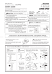
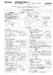
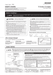
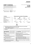
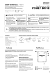
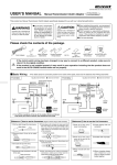
1
Mega
(VS-M As of March, 2008 No.2)
Voltage Stabilizer
High Capacity System & Battery Performance Monitor
Mega RAIZIN
Please check the contents of the package.
USER'S GUIDE
Thank you for purchasing PIVOT “Mega RAIZIN”. Please read these instructions carefully
before installing or using this device. Please do not lose this user’s guide, as you will held liable
for the cost of reissuing it.
CAUTION
Main Unit
M6 Nut
Double-sided
Tape 3
2
User’s Guide
Improper use or disregard of these warnings may result in the injury or death of people.
•Do not work in areas where there is excessive exhaust •Please securely fasten the product to a stable place
•Safety Precautions for Installation and Checking Operations •Do not crush the cable
Due to vehicle exhaust emission poisoning or fire may result in a damage
to humans.
Make sure to install and fasten the unit to a safe place that will not
become entangled in a fan or belt.
When the key is switched to ON, there is a possibility that the fan or belt
may suddenly begin moving and cause bodily injury. When doing any
work, make sure that the key is switched to OFF and when checking
operation make sure not to put your face or hands in a close position
which could cause bodily injury.
Please do not place the unit or the wires in any place that is exposed to
high temperature nor near any rotating objects such as a fan or belt.
Wires may become broken causing a short and/or fire. Do not splash
water on the unit.
•Do not allow water to come into contact with the unit.
The unit has been processed for water resistance but do not splash
with water when washing the car and so on.
•This product is for DC12V cars;
installation cannot be carried out on cars with other voltage
batteries.
Stabilize Voltage and Know when Battery Performance is Reduced !
FEATURES
Results you can 1.The unit assesses battery performance through changes in lowest voltage readings and when it has been judged to be reduced allows the user to take
necessary measures to improve performance (replacement, recharging, etc...) and thereby provide voltage stability to all electronic devices.
count on
2.The condenser circuitry reduces electrical noise and provides a stable voltage supply to the ignition coil as well as all other electronic devices.
NOTE
•About Improved Performance......
•About Judging Battery Life......
Installation of this product will lead to improvement in electrical aspects of your automobile but due to actual car and driving conditions
these improvements may be negligible or in some cases no change will occur.
Depending on the characteristics of the battery itself even a small change in the lowest voltage reading may signal the end of a battery's life.
Voltage Stabilizer
A World's First: View Battery Performance via Lowest Voltage Display
Our newly designed three-fold (compared to Blue Raizin) large capacity condenser
and our newly designed filter circuitry results in decreases in both circuitry noise
and high frequency impedance which results in a more stable supply of voltage to
the ignition coil and all electronic devices as well as improvements in power loss.
Displaying two types of voltage, both "Real" and "Lowest" Voltage (world first) at
engine start makes it easy to see battery life and loss in battery performance. This
also helps to protect against trouble caused by shortages in voltage to various
electronic devices.
INSTALLATION PROCEDURE
Make sure that
and
BASIC WIRING
WARNING
Please install safely and surely by following these
instructions.
In particular, please be very careful about
connecting the
and
cables. Mixing these up
will cause damage to the product.
are connected correctly.
M6 Nut
Battery terminal
Battery terminal
Cable
M6 Nut
Red Colored
Insulation Cap
Blue Colored
Insulation Cap
RAIZIN
Unit
. Wrenches (Socket Wrench . Combination Wrench)
. Vinyl Electrical Tape . Cloth . Absorbing Agent
1 Installation Preparation
3 Connect the
terminal of the battery.
1 Remove the cover from the
cable (one with red colored
Connect the unit's
battery cable.
insulation cap) to the terminal of the
Cable terminal
CAUTION
Battery terminal
Insulate with
vinyl tape.
To prevent making any mistakes with the
and
and causing a short during installation,
please make sure to insulate.
2 Installing the RAIZIN unit.
.
.
If you're installing on the top surface,
make sure the car hood will not to
hit the unit when closed.
. Fasten with an M6 nut to the original bolt.
. Fasten between the original nut and the terminal.
Original Bolt
M6 Nut
2 Replace the cover after completing the connection.
Red Colored
Insulation Cap
Cable
4 Check Wiring
terminal of the battery.
1 Remove the vinyl tape from the
cable (with blue cap) to the battery's minus
terminal.
2 Connect the minus
3 If the wiring has been completed correctly the voltage should appear and after ten seconds
automatically shut off.
and
are correct.
Please make sure to check about connecting the
and
WARNING cables. Mixing these up will cause damage to the product.
the cables go out the bottom.
Connect the unit's
Do not to install in areas subject to water.
Due to characteristics of the product, upon
to the battery's
contact of the RAIZIN'S
or upon the shorting of the flow of
current sparks may be emitted. This is not a defect.
.
bottom of the unit.
Waterproof Sheeting, etc.
2 Clean off all oil and dirt from the bottom of the main
unit and affix the double-sided tape included in the kit.
3 Clean off all oil and dirt from the installation place and
fasten the main unit.
5 Connect the
Cable
1 Properly connect the
cable terminal to the
battery
terminal.
2 Connect the unit's
cable (one with blue colored
battery cable.
insulation cap) to the terminal of the
. Fasten with an M6 nut to the original bolt.
. Fasten between the original nut and the terminal.
CAUTION
1.If you're installing on the side surface, the double-sided
tape will take about two hours to become secure.
During that time do not allow any vibration to the unit.
2.Reinstalling will cause the tape's adhesive strength to
weaken, so please do not to it.
cable
Sparking upon Contact
Circuitry has waterproof coating. But do not to install in areas subject to water or spray
with water.
If you install with the cables
Do not allow water to come
going out the top, water
into contact with the unit.
may enter the unit and
If it is a good chance of water
cause damage. Make sure
coming into contact, please
to install with cables
cover with waterproof
sheeting.
going
out
the
.
Cable terminal
Battery
terminal
. If voltage is not displayed = please check the connection and make sure
If you're installing on the side surface, install so
that
Cable
If the cover does not insulate properly, please use
vinyl tape to ensure proper insulation.
1 Decide installation place.
Without forcing, make sure you can connect
the two cables to the correct terminals.
Make sure the installation place is a flat
surface where the unit can be fixed with
double-sided tape.
Ex) The top or side of the battery or any other
flat surface near the battery. (fuse box, etc...)
1
Battery terminal
Cable
1 Remove the
2 Insulate the
cable from the
battery terminal.
battery terminal with vinyl tape.
Earth Terminal
Cable
Digital
Display
Things to prepare
If an earth terminal is installed...
Battery
terminal
Original Bolt
M6 Nut
Blue Colored
Insulation Cap
Cable
If an earth terminal is installed, connect the cable to the terminal.
(See [BASIC WIRING])
CLEAN TO REMOVE
OIL & DUST
6 Arranging the Cables
Arrange the cables with the lock ties included.
ASSESSING BATTERY PERFORMANCE
The lowest voltage at engine start is measured and if a change (lower measurement) is detected the battery's performance and life will be
judged to have been reduced.
HOW TO CHECK VOLTAGE
Judging Reduced Battery Performance (Lowest Voltage)
Judgments about reduced battery performance (life) can be made by checking the lowest voltage reading for a new battery at engine start and using that
reading for comparison. In order to do this, this unit measures and displays lowest voltage at engine start and thereby helps to prevent the following troubles
associated with reduced battery performance.
Possible Causes
Trouble
Reduced electronic device output caused by unstable voltage supply.
Poor mileage, reduced torque, poor starting, sound and reduced light brightness.
Reduced electronic device output caused by increased noise.
Reductions in mileage and torque as well as in sound quality due to increase in noise.
Reduced output due to lack of battery charge.
Troubles in starting engine and dead batteries.
About Judging Reductions in Performance from Changes in Voltage
Voltage(V)
15
ACC
IG ON
Engine Start
Real Voltage
14
If the difference in lowest voltage measurements for a new battery falls
13
1V to 1.5V , the battery's performance can be deemed to be reduced and
Engine Running
12
we strongly suggest taking the battery to a repair shop for checking and
recharging.
11
10
By "new battery" we mean a battery that has not been used for more than six
months; if a battery has been used for more than six months a change of
9
0.5V to 0.8V
7
Lowest Voltage
New Battery
Ex : 7.5V
8
should be viewed as a sign that performance has been
reduced and the battery should be checked.
Normal Range
1~1.5V
6
0
5
10
Reduced Battery
Performance
(Check Required)
20
(S)
Judgment Method
Engine Start
Check the Lowest
Voltage of New Battery
Please have battery checked periodically (every
month) or if the following occurs:
Periodic Check
.The engine seems not to start well
.The lights seem dark .The battery frequently dies out
0.7V reduction since new
ON
Usable
Ex : 7.5V (Blink)
Note that this method can only provide a rough
guideline and battery life varies greatly depends on the
individual characteristics of batteries and automobiles.
Normal
Ex : 6.8V (Blink)
2.1V reduction since new
Check
Ex : 5.4V (Blink)
Also note that even with properly working batteries, large
reductions (about 1V) in lowest voltage readings can occur
when outside temperatures are low (below 5 ) or starting
after having forgotten to turn off the lights.
Note that this measurement method can only provide a
rough guideline and that lowest voltage readings and battery
life varies greatly depending on the individual characteristics
of the battery being used.
Reductions in
Performance
Checking while Engine is Running (Real Voltage)
If voltage falls outside an acceptable range while the engine is running one of the following may be the reason and a check should be carried out.
If it is too high (15V or more)
Possible
Causes
Trouble
If it is too low (11.5V or less)
The alternator is broken (Regulator)
Possible
Causes
1. The fan belt is too loose or is torn.
2. The alternator or battery does not work properly.
Lowered performance of electronic devices or reduced battery life.
Trouble
Deterioration in mileage, torque, starting, sound and light brightness.
Measurement Method
When the engine is started, two types of voltage measurement (lowest voltage at engine start and real voltage) will be displayed for a
short time (about one minute) and then will automatically shut off.
Engine Start
Voltage Displays (Displayed alternately for about sixty seconds)
Lowest
Voltage (3 Seconds)
Real
Voltage (5 Seconds)
Lowest
Voltage (3 Seconds)
After 60 seconds
Real
Voltage (5 Seconds)
ON
After 60
seconds
Ex : 7.5V (Blink)
Ex : 14.2V (Light up)
Ex : 7.5V (Blink)
Automatically
turned off
Ex : 13.8V (Light up)
If you wish to re-measure the lowest voltage at engine start please perform only after the display has automatically turned off.
Note that if you are using a remote control starter to start your engine, the display will turn off after about one minute
and cannot be viewed.
PIVOT CORPORATION
87-3, Shimookada Okada, Matsumoto-shi, Nagano, 390-0313 Japan
TEL0263-46-5901
h ttp ://p ivotjp.com/
2