1
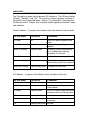
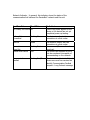
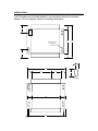
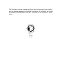
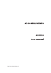
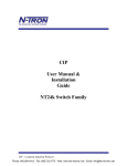
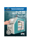
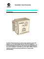
DeviceNet* Dual Clinometer
DESCRIPTION:____________________________________________
The Matric Dual Inclinometer is a smart sensor capable of measuring
angles of +/- 55º in two orthogonal axes. The unit is capable of
communicating to a DeviceNet* scanner, which is the gateway to a PLC
or PC monitoring & control system. The fully sealed rugged aluminum
enclosure is designed to withstand long-term abuse, making it ideal for
industrial applications requiring measurement of several axes
simultaneously.
SPECIFICATIONS:__________________________________________
Performance
• Total Range: +/- 55º
• Linear Range: +/- 40º
• Threshold: 0.001º
• Linearity:
Null to 5º: +/- 0.1º
5 to 40º: +/- 1%
40 to 55º: monotonic
• Null Repeatability: 0.05º
• Cross Axis Error: <1% up to 45º
• Time Constant: 0.3 second
• Frequency Response (-3db): 0.5 Hz
Power Requirements
• Network supplied
11-24 VDC
110-55 mA respectively
Communications
• 125K, 250K, 500K baud
• Media Access Control Identifier (MAC ID)
• Group 2 predefined master/slave connection set
• Binary Range: 15 bits + sign bit
• Scale Factor: 500 counts / degree
Diagnostics
• LEDs
Bi-color, red/green
DeviceNet* standard (Module, Network, I/O)
Environmental
• Sealed: IP65
• Operating Temperature: -30º to 65º C
• Storage Temperature: -55º to 65º C
• Temperature Coefficient
Null: 0.008º / ºC
Scale Factor: 0.1% / ºC
Dimensions
• Enclosure: 3.343 inches X 4.7 inches X 2.926 inches
• Mounting Flange: 5.669 inches X 3.9 inches
APPLICATION:____________________________________________
The Dual Inclinometer measures inclination in two axis using liquid filled
capacitive sensors and outputs the data in response to a poll message from a
DeviceNet* scanner. The nature of the sensors provides a certain vibration
dampening effect that is desirable in certain applications.
The Dual Inclinometer is calibrated to absolute “zero” (level) at the factory by
establishing an internal offset in software. In other words, the angle sensors
inside the unit are not physically leveled with respect to the enclosure, but the
unit’s software will compensate and give the proper “zero” degree reading when
the unit is level. A side effect of this calibration method is that the angular
measurement range specification of the sensors will be asymmetrical by their
particular amount of offset from “zero”. A similar process can be used after the
Dual Inclinometer is mounted to equipment to determine an offset that the
equipment logic can use to determine level.
CONFIGURATION:__________________________________________
The Dual Clinometer is configured via DeviceNet* using a configuration device
such a handheld Allen Bradley DeviceView or a PC running RS Linx and RS
Networx. DeviceNet devices use Electronic Data Sheets (EDS) to provide the
information needed to configure the device and setup a scanner and PLC for
communication with the device. An EDS file for the Clinometer is available on
the Matric web site. A device profile document is also available which provides
additional information on the objects supported by the Clinometer.
The Dual DeviceNet Clinometer is shipped with a MACID set to 63 (decimal). It
is typical for new DeviceNet devices to have a MACID of 63, therefore, the
MACID should be set to a different network address after the Clinometer is
added to a network. To avoid conflicting addresses and confusing device
identities, make sure network address 63 is available before adding the
Clinometer to a network.
When the Clinometer is first added to a network, the indicators will show Module
solid green (indicating that the device is functioning), Network blinking green
(indicating that the device is not connected to any device in the network), and IO
blinking green (indicating that the device has data available, but is not being
asked to produce data). RS Linx will discover the Clinometer and add it to the
network as node address 63, DUALINCL.
The PLC and scanner can request sensor data from the Clinometer using an
explicit “Get Attribute Single” without adding it to the scanner card’s scanlist.
While the Clinometer is processing the explicit message the Network indicator
will show solid green, but the IO indicator will continue blinking since the device
is not being polled. If the Clinometer is commissioned and added to the
scanner’s scanlist, all indicators will show solid green indicating that it is working,
connected to the scanner, and being polled.
Run time data is produced by the Clinometer and is available by executing a Get
Attribute explicit message sequence. RS Networx provides a dialog called the
Class Instance Editor which can be used to manually execute a Get Attribute
request. The Clinometer sensor data is the third Attribute (3) in the first
Instance (1) of the Assembly Object (Class 4). The Clinometer will respond to a
Get Single Attribute request by producing two 16 bit values. The first word
corresponds to the A axis shown on the Clinometer label. The second word
corresponds to the B axis. The most significant bit of the value is a direction bit.
When the direction bit is set (1), the Clinometer is tilted in the “-” direction as
shown on the Clinometer label.
Data tables and ladder logic can be used to execute the explicit Get Single
Attribute request in an operational PLC control system. The system integrator
will create a data table which holds the explicit request information as shown
below. An explicit request consists of a Transaction Header followed by
Transaction Data. In the Transaction Header, the COMMAND field is set to 1 to
tell the scanner to execute the request, the SERVICE field is set to 0x0E to
request a Get Single Attribute, and the SIZE field is 6 to show the number of
bytes of transaction data in the request. The remaining header field values are
chosen by the system integrator. In the Transaction Data, the first word is the
CLASS (4), the second word is the INSTANCE (1) and the last word is the
ATTRIBUTE (3). This data is copied by the PLC to the scanner’s M0 file to
execute the request. The scanner will place the Clinometer’s response in the M1
file for the PLC to retrieve.
TxId (0x??)
Command (0x01)
Port (0x??)
Size (0x06)
Service (0x0E)
MAC Id (0x??)
Class (0x0004)
Instance (0x0001)
Attribute (0x0003)
For more information, please refer to the following documents which are
available from Allen Bradley / Rockwell or the ODVA (Open DeviceNet Vendors
Association).
BULLETIN 1203-GK5 & 1336-GM5, 1747-SDN DEVICENET SCANNER (SLC-500)
EXPLICIT MESSAGING, Faxback Document # 3040, Web Location www.ab.com,
Pages 7 and 8 show how to set up data tables to send explicit messages and
receive the response message. Page 9 shows how to set up ladder logic to
communicate using explicit messages. Pages 10-14 give examples of data
tables.
THE CIP NETWORKS LIBRARY, Volume 1, Common Industrial Protocol,
Publication Number: PUB00001, Web Location www.odva.org, Appendix A covers
explicit messaging and section A-4-12 deals specifically with the Get Attribute
Single service request. Chapter 7 deals with EDS files and configuration issues.
1747-SDN DeviceNet Scanner Module User Manual, Catalog Number 1747-SDN
Series C, Publication 1747-UM655B-EN-P, Web Location
www.rockwellautomation.com, Appendix E deals with explicit messaging. Page
144 gives a basic overview of how a DeviceNet* system processes an explicit
message. Pages 150 and 151 contain tables showing service codes and error
codes.
INDICATORS:________________________________________________________
The Clinometer provides three diagnostic LED indicators. The LEDs are labeled
“Module”, “Network”, and “I/O”. The behavior of these indicators conforms to
DeviceNet* and is described below. Refer to “The DeviceNet* Communication
Model and Protocol” Chapter 8 for complete details regarding DeviceNet* states
and indicators.
Module Indicator - In general, this indicator shows the status of the unit itself.
For This State:
The LED is:
To Indicate:
No Power
Off
Device Operational
Green
Device In Standby
Flashing Green
There is no power applied to the
device.
The device is operating in a normal
condition.
The device needs commissioning
due to configuration missing,
incomplete, or incorrect.
Minor Fault
Flashing Red
Unrecoverable Fault Red
Device Self Testing
The device has a recoverable fault.
The device has an unrecoverable
fault and may need to be replaced.
Flashing Red/Green The device is in self test.
I/O Indicator - In general, this indicator shows the status of the unit.
For This State:
The LED is:
To Indicate:
No Power
Off
Not used.
I/O Active
Green
I/O Ready
Flashing Green
The unit is transmitting angle data
to the network.
The unit is reading angle data from
the sensors but is not being polled.
N/A
Flashing Red
Error
Red
N/A
Not used.
The unit is not reading data from
the sensors.
Flashing Red/Green Not used.
Network Indicator - In general, this indicator shows the status of the
communication link between the DeviceNet* network and the unit.
For This State:
The LED is:
To Indicate:
No Power/ Not Online Off
There is no power applied to the
device or the device has not yet
completed power up testing.
Online, Not
Connected
Flashing Green
The device is online, but has no
connections to other nodes.
Link OK
Green
Connection
Time Out
Critical Link Failure
Flashing Red
The device is online, and has
connections to other nodes.
One or more I/O connections have
timed out.
The device has detected an error
that has rendered it incapable of
communicating on the network.
Communication
Faulted
Flashing Red/Green The device has detected a Network
Access error and has received an
Identify Communication Faulted
Request – Long Protocol message.
Red
INSTALLATION:_______________________________________________________
The Clinometer can be bolted directly to a control panel using the mounting
flanges. See the diagram below for mounting dimensions.
0.59
1.06
DEVICE
NET
3.56
4.75
See Detail A for
mounting hole
dimensions
1.16
0.59
0.28
5.66
0.66
2.91
1.44
0.66
0.66
Detail A
0.75
4.16
0.75
5.06
0.30
0.30
The Clinometer provides a sealed male (pins) mini style connector that complies
with the physical standards for DeviceNet* connectors. A DeviceNet* tap is used
to interface to the DeviceNet* trunk line. The pinout for the connector is shown
below.
5
4
1
2
3
1 - Drain
2 - V+
3 - V4 - CAN_H
5 - CAN_L
Matric
2099 Hill City Road
Seneca, PA 16346
814-677-0716
www.matric.com
Document: OM 185-0058 R1.doc
*DeviceNet is a registered trademark of ODVA
Copyright 2008, Matric