1
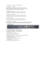
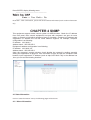
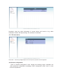
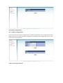
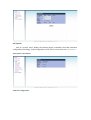
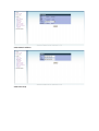
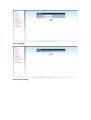
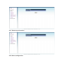
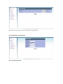
AD INSTRUMENTS AD2028 User manual http://www.abacantodigital.com Caution Statements: Please observe the following safety requirements before operating the equipment. CONTENTS Chapter 1 Introduction.....................................................................................................................1 1.1 OVERVIEW...........................................................................................................................1 1.2 MAIN FEATURES...............................................................................................................1 1.3 SPECIFICATIONS…...........................................................................................................1 MPEG-TS Input..................................................................................................................................1 1.4 Illustraion.............................................................................................................................3 1.4.1 Front panel..................................................................................................................3 1.4.2 Rear panel...................................................................................................................4 Chapter 2 Installation.......................................................................................................................5 2.1 Unpacking...........................................................................................................................5 2.2 Installation............................................................................................................................5 2.2.1 Device’s Installation Flow Chart Illustrated as following˖...........................5 2.2.2 Environment Requirement......................................................................................5 2.2.3 Grounding Requirement..........................................................................................6 2.2.4 Frame Grounding......................................................................................................6 2.2.5 Device Grounding......................................................................................................6 Chapter 3 Operation.........................................................................................................................7 3.1General Config.....................................................................................................................7 3.2Detail Config.........................................................................................................................7 3.2.1Output Config..............................................................................................................8 3.2.2.Transmission..............................................................................................................9 3.3 TS Info..................................................................................................................................10 3.4 Alarm....................................................................................................................................10 3.5 System..................................................................................................................................11 3.5.1 System Info...............................................................................................................11 3.5.2 System Config..........................................................................................................11 3.5.2.1 Test Confgi.............................................................................................................11 3.5.2.2 Network...................................................................................................................13 3.5.2.3 Time Setup.............................................................................................................13 3.5.2.4 Language................................................................................................................13 3.5.2.5 Factory Settings...................................................................................................13 3.5.2.6 Delete Log Info......................................................................................................14 CHAPTER 4 SNMP..........................................................................................................................15 4.1 State information.................................................................................................................15 4.1.1 Alarm information...................................................................................................16 4.1.2 TS information.........................................................................................................16 4.2 General configuration.........................................................................................................17 4.3 Detail configuration.............................................................................................................17 4.3.1 output configuration..............................................................................................17 4.3.2 Transmitting parameter.........................................................................................18 4.4 System...................................................................................................................................18 4.4.1 Systme information..............................................................................................19 4.4.2 Test configuration................................................................................................19 4.4.3 Network address...................................................................................................20 4.4.4 Time setup..............................................................................................................20 4.4.5 Language................................................................................................................21 4.4.6 factory setting........................................................................................................21 4.4.7 Delete log information.........................................................................................22 4.4.8 Alarm configuration.............................................................................................22 4.4.9 Subscriber management.....................................................................................23 4.4.10 Log information...................................................................................................23 Chapter 1 Introduction 1.1 OVERVIEW DMB-2028 DVB-T modulator is designed to meet the most demanding of today’s digital terrestrial TV broadcast market, which is applied especially to the medium and small terrestrial digital TV systems and enterprises. It supports DVB-T whole working modesూhierarchical mode as well as VHF and UHF band frequency agile signal output. With high quality RF signal, it directly drives the low power digital TV transmitter, and contains such three test modes as NULL insertion, PRBS sequence, test stream, which supply comprehensive and reliable DVB-T signal source system for R&D company or manufacturer. DMB-2028 DVB-T modulator is the cost-effective modulator. 1.2 MAIN FEATURES · · · · · · · · DVB-T supported 2K, 8K modes supported Frequency agile 48MHz ~870MHz, in 1Hz step 0dBm RF output level,10dB attenuation range, in 0.1dB step Bit rate adaptation and PCR re-stamping High quality RF modulation 3 kinds of TS test modes Web browser remote control, SNMP supported 1.3 SPECIFICATIONS MPEG-TS Input · comply with ETS 300744 and TS101191 · 1 ASI input, bit rate adaptation · 188 Bytes supported · ASI packet modes: burst/byte · Max effective bit rate: up to 31.67Mbps · Connector: BNC, 75 ohm RF Output · Frequency48MHz ~ 870MHz, in 1Hz step · Main Output Level: 0dBm Attenuation: -10dB–0dB in 0.1dB step Monitoring output: -20 dB Return Loss: >15dB Level Stability: ±0.5dB · I/Q amplitude unbalanced: <0.05% · I/Q quadrature error: <0.05º · MER: >40dB · Spurious: >55dB(related to the whole signal power) · Connector: N, 50ohm TS Test Mode · NULL symbol insertion · PRBS sequence · Test stream Modulation and code · Supported ETS 300744 standard · · · · · · · · Supported Modes: DVB-T FFT: 2K, 8K Guard Intervals: 1/4, 1/8, 1/16, 1/32 FEC: 1/2, 2/3, 3/4, 5/6, 7/8 Constellations: QPSK, 16QAM, 64QAM Inner interleave: Native Channel Bandwidth: 6MHz, 7MHz, 8MHz, TPS signal: DVB-T Clock and Synchronization · Internal reference clock 10MHz (OCXO) Control · Front Panel · Web browser remote control, SNMP supported Mechanical Parameter · Voltage: AC 90~260V, 50~60Hz · Consumption: 40W · Operating temperature: -10~50ఁ͑͑ · Storage temperature: -20~70ఁ͑͑ · Humidity: 10%-95% · Dimension: 400mm(L)X430mm(W)X45mm(H) · Weight: 6kg 1.4 Illustration 1.4.1 Front panel There are 2x40 character LCD, 3 indicators, 6 buttons in the front panel. 1.4.1.1 Indicator · Power indicator (green) If the indicator is light, it means power on. · Alarm indicator (redి͑͑ If the equipment is working abnormal, the indicator will be light. The alarm indicator will be lit if appear the following one or several cases None TS input Input bit rate overload͑ష͑͑ · Lock indicator(red) LO is unlocked, the indicator will be red. 1.4.1.2 Button There are 4 cursor keys, 1 Enter key, and 1 Cancel key, which can browse and operate menu system to complete system configuration. · UP keyాUPి͑͑ Move up the cursor key in the status of browsing the menu. Rotate parameter in the editing status of enumerating parameter Add parameter in the status of parameter editing · DOWN keyాDOWNి͑͑ Move down the cursor key in the status of browsing the menu. Rotate parameter in the editing status of enumerating parameter Reduce parameter in the status of parameter editing · LEFT keyాLEFTి͑͑ Move left the cursor key in the status of browsing the menu. Move left the cursor key in the status of parameter editing · RIGHT keyాRIGHTి͑͑ Move right the cursor key in the status of browsing the menu. Move right the cursor key in the status of parameter editing · ESC key:ాESCి͑͑ Return to previous menu in the status of menu browsing Return to current menu in the status of parameter editing. · ENTER keyాENTERి͑͑ Enter into the sub-menu which cursor locate in when browse the menu system. Save the results of amending parameter in the state of editing parameter. 1.4.2 Rear panel · RF output connectorాRF OUTి͑͑ N-type connectorా50ohmిూoutput RF signal · Output monitor connectorాRF MONITORి͑͑ BNC connectorా50ohmిూmonitor RF output · Input connectorాASI INి͑͑ 1 BNC connectorా75ohmి,input ASI · Output connectorాASI OUTి͑͑ 1 BNC connectorా75ohmి,output ASI which is same as ASI IN · RS-232 connector DB9ాmaleి͑connector is for remote control · 10/100 Base T connector RJ-45 connectorూconnect with Ethernet · Power connector Power socket, there is ON/OFF switch. P-5 Chapter 2 Installation 2.1 Unpacking Please unpack the box to check whether all of the following items are included in the packaging˖ · DMB-2028 DVB-T Modulator User Manual Power cord BNC cable · · · 2.2 Installation When users install device, please follow the below steps. The details of installation will be described at the rest part of this chapter. Users can also refer rear panel chart during the installation. The main content of this chapter including: · Checking the possible device missing or damage during the transportation · Preparing relevant environment for installation · Installing equipment · Connecting communication port (if it is necessary) 2.2.1 Device’s Installation Flow Chart Illustrated as following˖ 2.2.2 Environment Requirement Item Requirement Machine hall space When user install machine frame array in one machine hall, the distance between 2 row of machine frames should be 1.2~1.5m and the distance to wall should be no less than 0.8mDŽ Machine hall floor Electric Isolation, Dust Free Grounding current limiting resistance: 1M Floor bearing should be greater than 450Kg/m 2 Environment temperature 5~40(C sustainable ˈ0~45(C short timeˈ installing air-conditioning is recommended 20%~80% sustainable 10%~90% short time Relative temperature Pressure Door & window Wall Fire protection Power 86~105KPaDŽ Installing rubber strip for sealing door-gaps and dual level glasses for window It can be covered with wallpaper, or brightnessless paint. Fire alarm system and extinguisher Requiring device power, air-conditioning power and lighting power are independent to each other. Device power requires AC power 220V 50Hz. Please carefully check before running. 2.2.3 Grounding Requirement All function modules’ good grounding designs are the base of reliability and stability of device. Also, they are the most important guarantee of lightning arresting and interference rejection. Therefore, system must follow this rule. Coaxial cable’s outer conductor and isolation layer should keep sound electric conducting with the metal housing of device. Grounding conductor must adopt copper conductor in order to reduce high frequency impedance, and the grounding wire must be as thick and short as possible. The 2 terminals of grounding wire must make sure for well electric conducting, and process for antirust. It is prohibited that users use other devices as part of grounding wire’s electric circuit The section of the conjunction between grounding wire and device’s frame should be equal or greater than 25mm2 2.2.4 Frame Grounding All the machine frames should connect to protective copper strip. The grounding wire should be as short as possible and avoid circling. The section of the conjunction between grounding wire and grounding strip should be equal or greater than 25mm2 2.2.5 Device Grounding Connecting the device’s grounding rod to frame’s grounding strip with copper wire. Chapter 3 Operation Power on, the LCD will display following information: ---------------------------------------------------------- Hangzhou DIGICAST DVB-T Modulator ---------------------------------------------------------Press ENTER key to enter into main menu(switch menu via UPER/DOWN key, press ENTER to enter) Display following information: ---------------------------------------------------------- Alarm… TS Info… General Config… Detail Config… System… ---------------------------------------------------------- 3.1General Config Move the cursor to General Config, press ENTER key , display following menu: ---------------------------------------------------------- Signaling mode˖ DVB-T(*) ---------------------------------------------------------- 3.2Detail Config Move cursor to Detail Config, press ENTER, display following menu:˖ ---------------------------------------------------------- Output Config… Transmission… ---------------------------------------------------------Press UP/DOWN key to browser men, press ENTER key to enter into sub-menu, press EXIT to return previous menu. 3.2.1Output Config Move cursor to Output Config, press ENTER, display following menu:˖ ---------------------------------------------------------- RF Center Freq˖ 720000000Hz˄48 ˉ870M˅ RF attenuation˖ 1.6dB(0.0 - 10.0dB) RF Output˖ Close RF Output Delay 2Min˄0ˉ5Min˅ ---------------------------------------------------------All menus can be switched via UP/DOWN keys. Explain the function of each menu as following: RF center frequency range˖48̚870MHz default˖720 MHz note˖adjustment in 1Hz step ƽRF attenuation range˖0 ̚10dB default˖1.6dB illustration˖adjustment in 0.1dB step ƽRF output range˖open/close default˖close illustration˖open means RF output is working, close means RF output is prohibited. ƽRF output delay range˖0 ˉ5Min default˖2Min illustration˖power on, system RF will open time delay configuration automatically. 3.2.2.Transmission 0RYHFXUVRUWR7UDQVPLVVLRQSUHVV(17(5GLVSOD\WKHIROORZLQJPHQX ---------------------------------------------------------- Modulation˖ 64QAM(*) Code Rate˖ 2/3(*) Guard Interval 1/4(*) FFT Mode 8K(*) Channel Bandwidth 8MHz(*) ---------------------------------------------------------Explain the function of each menu as following: ƽChannel Bandwidth range˖6 MHzˈ7 MHzˈ8 MHz default˖8 MHz illustration˖channel bandwidth ƽFFT mode range˖2Kˈ8K default˖8K illustration˖2Kˈ8K optional ƽguard interval range˖1/32ˈ1/16ˈ1/8ˈ1/4 default˖1/4 illustration˖guard interval ƽModulation range˖64QAMˈ16QAMˈQPSK default˖64QAM illustration˖modulation ƽCode rate range˖1/2ˈ2/3ˈ3/4ˈ5/6ˈ7/8 default˖2/3 illustration˖code rate 3.3 TS Info Move cursor to menu, press ENTER to display following menu: ---------------------------------------------------------- Packet Length˖ 188 TS Input Bit rate˖ 0.000000Mbps TS Payload˖ 0.000000Mbps ---------------------------------------------------------- 3.4 Alarm Display related alarm information, alarm information include: 1ˊASI input missing illustration˖don’t find the TS input, check whether the correction is correct. 2ˊTS overload illustration˖the input TS payload is greater than output bit rate of current system mode. 3ˊLO unlocked illustration˖up-converter LO is unlocked 3.5 System Move cursor to menu, press ENTER to display following menu: ---------------------------------------------------------- System Info… System Config… ---------------------------------------------------------Press ENTER to browser menus, press ENTER to enter into sub-menu, press EXIT to return previous menu. 3.5.1 System Info ----------------------------------------------------------------------- Unit Name˖DVBˉT Modulator HW #˖HW-1.0.0.04 SW Version… ---------------------------------------------------- 3.5.2 System Config ---------------------------------------------------------- Test Config… Network… Time Setup… Language… Factory Settings… Delete Log Info… ---------------------------------------------------------- 3.5.2.1 Test Config ---------------------------------------------------------- SRRC filter Working(*) Single Tone˖ disable(*) TS Test mode˖ disable(*) Spectrum˖ invert(*) --------------------------------------------------------- ƽSRRC filter range˖bypassˈworking default˖working illustration˖it should be working under normal condition, otherwise the spectrum shoulder will be very bad; During MER test, if test equipments is none balance, it should be bypassing filter, otherwise MER is not good. ƽsingle tone range˖disableˈenable default˖disable illustration˖disable, normal spectrum mode, enable single mode ƽTS test mode range˖1.disable; 2.PRBS; 3.test stream; 4.Null is inserted˗ fault˖disable illustration˖ 0: TS from ASI connector 1: PRBS which is native generated 2: test stream which is native generated 3: MPEG null package which is native generated ƽSpectrum invert range˖normalˈinvert default˖invert illustration Normal: normal spectrum output invert: invert spectrum output 3.5.2.2 Network ---------------------------------------------------------- IP˖192.168.000.118 Mask˖255.255.255.000 Gateway˖192.168.000.001 ---------------------------------------------------------Press UP/DOWN key to switch for choose, press ENTER to enter into editing status, direction key is for amending, press ENTER to confirm 3.5.2.3 Time Setup ---------------------------------------------------------- Date˖1999.11.30 Time˖00:43:13 ---------------------------------------------------------Press UP/DOWN key to switch for choose, press ENTER to enter into editing status, direction key is for amending, press ENTER to confirmDŽ 3.5.2.4 Language illustration˖Chinese/English menu switch press ENTER to edit, direction key to amend, press ENTER to confirm the amending. 3.5.2.5 Factory Settings Press ENTER, display following menu: ---------------------------------------------------------- Factory Settings˛ Enter ˙YesˈExit ˙No illustration˖press ENTER, system will return to factory settings. 3.5.2.6 Delete Log Info Press ENTER, display following menu: ---------------------------------------------------------- 'HOHWH/RJ,QIR" Enter ˙YesˈExit ˙No ---------------------------------------------------------illustration˖after confirmation, system will cancel the data information( such as alarm information etc) CHAPTER 4 SNMP This equipment support remote control system via WEB browser. Check the IP address from front panel, then connect equipment’s net port with computer’s net port via cross cable; or connect to LAN which equipment locate in via switch. Computer’s IP address and equipment’s IP address are set into same address segment, for example, computer configuration is as following˖ IP address˖192.168.0.2 Address mask˖255.255.255.0 Equipment’s address configuration is as following: IP address˖192.168.0.119 Address mask˖255.255.255.0 Open the computer’s console window, check whether the network is working smoothly among the equipments via ping tool. If the connection is right, we open the computer’s web browser, input equipment’s IP address (such as http://192.168.0.119/) in the address bar ,then you can see the following interface : 4.1 State information Click on “state information” menu, the following pages will be shown: 4.1.1 Alarm information illustration˖show the alarm information of current device and record to log, alarm information include: ASI input missing, TS overload, LO unlocked˗ 4.1.2 TS information illustration˖show the package depth of current input TS, input bit rate and payload 4.2 General configuration Click on “General configuration” menu, display the following pages, subscriber can make parameter configuration accordingly, finish configuration, press “save” to save them into equipments. 4.3 Detail configuration 4.3.1 output configuration Click on the sub-menu “output configuration” of “detail configuration” menu, display the following pages, subscriber can make parameter configuration accordingly, finish configuration, press “save” to save them into equipments 4.3.2 Transmitting parameter 4.4 System Click on “system” menu, display the following pages, subscriber can make parameter configuration accordingly, finish configuration, press “save” to save them into HTXLSPHQWV 4.4.1 System information 4.4.2 Test configuration 4.4.3 Network address 4.4.4 Time setup 4.4.5 Language 4.4.6 factory setting 4.4.7 Delete log information 4.4.8 Alarm configuration Illustration: configuration need to record alarm to log information 4.4.9 Subscriber management 4.4.10 Log information