1
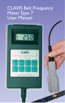
®
pT oe w
n es ri o tr
n Ra int s em i Bs es li o
t n f Pr Re Oq Du UC
e nT cS y
M et et ne sri o n r i t e
®
TensionRite Belt Frequency Meter
®
User Manual
Folio Edition
D i s t r i b u t e d B y:
Applied Industrial Technologies
1-877-279-2799
1
T e n s i o n R i t e
®
B e l t
f r e q u e n c y
M e t e r
Table of Contents
SECTION
PAGE
1.0Safety Tips....................................................... 3
2.0 Device Description............................................ 4
3.0Quick Start...................................................... 5
4.0Functions
4.1 Keys...................................................... 6
4.2Audio/Visual Display................................ 8
4.3Optical Sensor........................................ 9
4.4 Battery Condition.................................... 10
4.5Charging Batteries................................... 11
5.0Setup & Use Procedure..................................... 12
6.0Operating Tips.................................................. 14
7.0 Meter Range.................................................... 15
8.0Calibration
8.1Spot Check............................................. 16
8.2Annual Certification................................ 17
9.0 Technical Specifications.................................... 18
10.0Useful Formulas & Conversions.......................... 19
Appendix
1.0 Belt Mass Constants................................ 20
2.0 Theory of Operation................................. 23
3.0FAQ’s..................................................... 24
4.0 Tensioning Tables.................................... 28
5.0Limited Warranty.................................... 30
2
T e n s i o n R i t e
®
B e l t
f r e q u e n c y
M e t e r
1.0 GENERAL SAFETY TIPS
SAFETY FIRST –
Read and understand this manual before operating the
TensionRite® Meter.
• Do not drop meter or subject either meter or optical sensor to other sharp impact.
• Do not put water, solvents (including cleaning solutions) or any other liquid on the unit. Clean meter and sensor with a dry cotton cloth.
• Do not pull on sensor cord. Disconnect sensor from meter by grasping the connector grip only.
• Do not leave the unit in places that are humid, hot, dust filled or in direct sunlight. Hint: When the TensionRite® Meter is not to be used for a while, remove the
batteries and store unit in the case provided.
• Do not use your TensionRite® Meter in any explosive environment.
• Do not disassemble or attempt to modify either the meter or the sensing head.
LOCK OUT – TAG OUT
Switch off and isolate any belt drive system prior to taking tension measurements or
attempting any other installation work.
3
T e n s i o n R i t e
®
B e l t
f r e q u e n c y
2.0 Device Description
LED
Aiming
Beam
M e t e r
Display
Window
see Section 4.2
Key Pad
see Section 4.1
Optical Sensor
see Section 4.3
Cable
Plug-in
The TensionRite® Belt Frequency Meter from Goodyear Engineered Products is a two
component system consisting of a hand-held meter attached to an optical sensor via
an electronic cable. The sensor uses an infrared beam to detect the vibration of a belt
strand and sends a signal to the meter. (The sensor includes an LED that produces an
orange light beam to help aim the invisible infra-red ray). Comparing this input to the
vibration of a quartz crystal, the meter computes the natural frequency of the belt. The
result is shown in the display window as hertz (oscillations per second). The internal
programming of the meter is also able to report the belt tension in units of force (either
newtons or pounds-force) provided the operator has entered the belt mass and span
length using the manually operated key pad.
The meter operates on four “AA” batteries. Battery life is approximately 20 hours. The
battery compartment is accessible at the back of the meter.
An abridged manual, a tuning fork for checking calibration and a storage case are
included with the complete kit.
4
T e n s i o n R i t e
®
B e l t
f r e q u e n c y
M e t e r
3.0 Quick Start
Following these simple steps will allow you to measure the vibration frequency of the
belt. This value is independent of span or mass values but is very useful as an index for
belt system maintenance, sometimes the only number you will need. For example, the
MAXIMIZER™ drive analysis program gives tensioning targets in Hz as well as in force
units (newtons and pounds-force).
For tensioning results in units of force, follow the procedures defined in Section 5.0.
5
T e n s i o n R i t e
®
B e l t
f r e q u e n c y
M e t e r
4.0 Functions
4.1 Keys
ON/OFF
SPAN
(m)
MASS
(kg/m)
This key switches the meter on or off. If the meter is on and sits idle for
more than 3 minutes, it automatically switches off to preserve battery life.
When the meter is first switched on a battery check is made. See Section
4.4 for a description of the visual and audible low battery signal.
This key is used to enter the belt span length. Hold down the span key and
use the UP or DOWN keys to set the belt span in meters. Releasing the
span key results in an audible beep to indicate the setting has been
accepted. Pressing a MEM(ory) key immediately after releasing the SPAN
key will load the span constant just entered into the appropriate memory
register. Pressing the SPAN key alone shows the current setting.
This key is used to enter the belt mass. Hold down the mass key and use
the UP or DOWN keys to set the belt mass in kilograms/meter (kg/m)).
Releasing the mass key results in an audible beep indicating that the
setting has been accepted. Pressing a MEM(ory) key immediately after
releasing the MASS key will load the mass constant just entered into the
appropriate memory register. Pressing the MASS key alone displays the
current setting.
Important Note:
Belt span and belt mass are required entries if tension results in force units (newtons or
pounds-force) are desired. Entries must be in SI units (meters and kg/meter).
UP
(Hz/N)
This key has two functions. The first is to increase either the SPAN or
MASS parameters when used in conjunction with those keys. The second
use is to toggle between the Hz and the newton measurement modes. If
this key is pressed while either the SPAN or MASS keys are being held
down, the number shown in the display window will increase in value. If
only this key is pressed, the display will automatically toggle between
frequency and newtons. The calculation of the force in newtons will be
based upon the mass and span constants currently in the active register.
6
T e n s i o n R i t e
DOWN
(Hz/Lbs)
MEM 1
MEM 2
MEM 3
®
B e l t
f r e q u e n c y
M e t e r
This key has two functions. The first is to decrease either the SPAN or
MASS parameters when used in conjunction with those keys. The second
use is to toggle between the Hz and the pounds-force measurement modes.
If this key is pressed while either the SPAN or MASS keys are being held
down, the number shown in the display window will decrease in value.
If only this key is pressed, the display will automatically toggle between
frequency and pounds. The calculation of the force in pounds will be based
upon the mass and span constants currently in the active register.
The memory keys allow up to three sets of belt parameters to be stored
in the meter registry. Pressing the MEM 1 key recalls the first set of belt
parameters and likewise for MEM 2 and MEM 3. To store the belt
parameters to a key, the belt span and mass parameters must first be
entered and then immediately after release of either the SPAN or MASS
keys the selected MEM key should be pressed. Two beeps indicate that
the parameters have been successfully assigned to the key.
To use the stored span and mass constants simply press the desired
MEM(ory) key prior to taking a measurement. To check if you have the
correct values you may press the SPAN or MASS keys and the current
constant will show in the display window.
7
T e n s i o n R i t e
®
B e l t
f r e q u e n c y
M e t e r
4.0 Functions
4.2 Audio/Visual Display
The TensionRite® Belt Frequency Meter is an interactive tool. It provides
both visual and audible communication with the operator. Each signal or
combination of signals has meaning. While all these signals are discussed
in other sections of this manual, here will be presented a compilation of all
the available signals.
Generally visual signals alone give measurement results while audible
signals, either alone or in combination with a visual signal, indicate some
operational step.
VISUAL MEASUREMENT RESULTS
Hz
lbs
N
lbs
N
Hz
000
000
000
Tension displayed in newtons
Frequency mode, results displayed as hertz (cycles/sec).
Tension displayed in pounds-force.
A dark oval will appear to indicate the units associated with the number
displayed.
AUDIBLE SIGNALS
Signal
when
means
One beep
Upon release of “Span” key
Upon release of “Mass” key
While sensor is aimed at vibrating belt
Upon pushing “memory” key after
releasing “Span” key
Upon pushing “memory” key after
releasing “Mass” key
Combined with “000” newton display
Combined with “000” pound display
After pushing “On” key and combined
with “zero” countdown
Input accepted
Input accepted
Measurement taken
Span data has been stored
Two beeps
Four beeps
Mass data has been stored
Newton result is out of range
Pound result is out of range
Low battery condition
8
T e n s i o n R i t e
®
B e l t
f r e q u e n c y
M e t e r
4.0 Functions
4.3 Optical Sensor
The sensor uses an invisible infrared beam to detect vibrations of the belt.
A narrow angle orange LED generated beam is provided to guide the aiming
of the sensor.
The very best signal from the belt is seen
when the sensor is held perpendicular to
the belt at the center of the span and at
a 3/8” (9.5mm) distance. It is also a good
practice to orient the long edge of the
sensor head parallel to the centerline of
the belt. This helps to reduce the effect
of any divergence between the aiming
beam and the infrared sensing beam.
When physical restrictions are present, it is possible to get useable readings
with the sensor at up to 2” distance from the belt and/or tipped up to 45
degrees from perpendicular.
It is possible to take measurements from
the edge of the belt. The toothed side of
a belt is equally acceptable as a target
for the sensor.
The sensor LED’s should be kept clean by wiping with a soft cotton cloth.
Solvents are never to be used.
9
T e n s i o n R i t e
®
B e l t
f r e q u e n c y
M e t e r
4.0 Functions
4.4 Battery Condition
When the TensionRite® Belt Frequency Meter is first switched on, a
battery condition check is automatically performed. A low battery condition
is signaled both visually and audibly. The display window will flash an array
of zeros, starting with four and progressing to only one. There will be an
audible signal of four “beeps” as the display changes.
N
Hz
lbs
N
Hz
lbs
N
Hz
lbs
N
Hz
lbs
0000
000
00
0
BEEP
BEEP
BEEP
Low
Battery
Signal
BEEP
If these signals are seen and heard, batteries should be replaced. Batteries
are accessed through the removable cover on back of meter. New batteries
should be inserted within 30 seconds of removal of old batteries. Taking
longer risks loss of any data stored by the memory keys.
Batteries are expected to provide approximately 20 hours of continuous
operation before replacement is required.
Dispose of old batteries in an environmentally sensitive manner as prescribed
by the battery manufacturer. In no case should the batteries be disposed of
in open flame.
10
T e n s i o n R i t e
®
B e l t
f r e q u e n c y
M e t e r
4.0 Functions
4.5 Charging Batteries
— IMPORTANT —
Do not charge batteries with the sensor head attached to the meter. Do
not attempt to use the meter while batteries are being charged. Damage
to the optical sensor could result.
The TensionRite® Belt Frequency Meter is compatible with user supplied
rechargeable batteries and recharging unit. A convenient 3.5mm, positive
center charging socket is located on the bottom end of the meter body
adjacent to the sensor cable plug-in port.
• Batteries – 1300 mAH minimum (user supplied)
• Charging unit – 12 to 15 volt DC output (user supplied)
• Connection – 3.5mm O.D. positive tip mini plug/socket
The built-in circuit of the meter controls the charging current, automatically
providing a fast and a trickle charge. Charging current is internally limited
to 100 mA. Charging time is typically 12-14 hours for a full charge.
You may turn the unit on while charging. The meter’s software will then
signal that the batteries are charging. The display window will flash an
array of zeros, starting with only one and progressing to four. There will
be an audible signal of four “beeps” as the display changes.
Alternatively, a separate battery charging station may be utilized. Using two
sets of batteries, one set in use with the meter, the other set in the charging
station would ensure freshly charged batteries were always available. Again,
batteries should have a minimum rating of 1300 mAH.
11
T e n s i o n R i t e
®
B e l t
f r e q u e n c y
M e t e r
ON/OFF
5.0 Setup & Use Procedure
SPAN
(m)
1.Plug sensor head into meter body. This is a keyed plug. Line it up, do not use force!
ON/OFF
MASS
(kg/m)
SPAN
2. Turn unit on (m)
by pressing
ON/OFF
ON/OFF
3. Load span and mass data or recall previously loaded data.
SPAN
ON/OFF
(m)
SPAN
To load span data
simply hold down
MASS
while using
(kg/m)
UP
(Hz/N)
or
DOWN
(Hz/Lbs)
(m)
SPAN
to set the number.
(m)
DOWNMASS
When the correct number appears
display window, simply release the
(kg/m)in the
MASS
(Hz/Lbs)
SPAN key. The unit will beep once to acknowledge
acceptance of this setting.
(kg/m)
DOWN
(Hz/Lbs)
To load mass data
simply hold down
DOWN
(Hz/Lbs)
while
using
UP
(Hz/N)
or
DOWN
MEM
1
(Hz/Lbs)
MASS
(kg/m)
to set the number.
MEM 21
When the correct number appears
in the display window, simply release the
MASS key. The unit will beep once
UP to acknowledge acceptance of this setting.
(Hz/N)
UP
MEM 3memory,
2
MEM 1entries into
To save individual
press the appropriate memory key
(Hz/N)
MEM 1
,
MEM 2
or
MEM 3
MEM 1
UP
(Hz/N)
as soon
span
3 or mass keys have been released. The meter will beep
MEM 2 as theMEM
MEM 2 into memory.
twice to acknowledge the entry
MEM 3
12
MEM 1
T e n s i o n R i t e
®
B e l t
f r e q u e n c y
M e t e r
MEM 2
MEM 1
To recall stored span and mass data simply press
MEM 1
according to where you previously entered the values.
MEM 2
4. Aim sensor at center of selected
ON/OFF practice is to orient
belt span. (Best
sensor with the long edge parallel to
the belt centerline as shown. Best
gap is approximately ½˝.) Tap or
pluck the belt.
Tapping the belt with
SPAN
the handle of a small tool such as a
(m)
screwdriver is a good way to make
the belt vibrate. The meter will beep
once to indicate that a measurement
was taken.
,
MEM 2
or
MEM 3
MEM 3
MEM 3
MASS
(kg/m)
5. Display window will show frequency results.
Hz
lbs
N
6. Press
7. Press
UP
(Hz/N)
DOWN
(Hz/Lbs)
to toggle results to newtons.
to toggle results to poundsƒ.
lbs
N
Hz
97.4
0225
0050
NOTE: Pressing either toggle a second time will return display to the Hz value.
8. Readjust belt tension and repeat measurement until target tension results are attained.
MEM 1
13
T e n s i o n R i t e
®
B e l t
f r e q u e n c y
M e t e r
6.0 Operating Tips
Here are some procedures and “best” practices that may ease use or help increase
the reliability of your belt tensioning efforts.
LOCK OUT - TAG OUT
• Take your tension reading as close to the center of the selected span as is practical.
• Use the longest belt span that can be readily accessed. Minimum useable span length is equal to 20 times the belt tooth pitch for synchronous belts and 30 times the belt
top width for “V” configuration belts. Using too short a span yields indicated tensions
that may be much higher than actual belt tension due to effects of belt stiffness.
• When possible, orient the sensor head with the long edge of the sensor parallel to
the centerline of the belt. This tends to eliminate any non-reading condition due to
aiming error.
• On new installations, hand rotate the system at least one full revolution of the belt to seat and normalize the components.
• If the top surface of the belt is not accessible, try to beam the sensor against the edge of the belt. The inside surface of the belt is equally acceptable.
• The meter will not give a measurement for a belt under extremely low tension. Simply increase the drive tensioning until the meter responds. The meter will beep to indicate that a reading has been taken.
• It is a good practice to take three successive readings. This will show the consistency
of your methods. If the readings vary by more than 10%, reassess your measurement
technique.
• Taking multiple readings at different belt orientations may help you identify problems with other drive components. Tension excursions are indicative of component problems such as a bent shaft, poorly mounted sprocket or pulley or an irregular pulley groove.
• The TensionRite® Belt Frequency Meter will measure vibration frequency (Hz) of all
style belts, even belts from manufacturers other than Goodyear Engineered Products.
Tension values will also be computed provided you input the appropriate span and
mass constants.
• When tensioning an array of multiple V-belts, use a single belt toward the center
of the array. Banded belts (Torque Team®, etc.) are to be treated as a single unit with
the mass constant calculated as a multiple of the single belt value (see “Belt Mass Constants”).
14
T e n s i o n R i t e
®
B e l t
f r e q u e n c y
M e t e r
7.0 Meter Range
The TensionRite® Belt Frequency Meter is capable of measuring belt vibration frequencies
between 10Hz and 400Hz.
If the measured frequency is below 10Hz, the meter will display “10.00” briefly and then
change to “000.0”. If the measured frequency is above 400Hz, the meter will display
“400” briefly and then change to “000”.
If these limits are exceeded on a multi-shaft (three or more shafts) system it may be
possible to get valid measurements by selecting a different belt span for measurement.
If the measured frequency is below 10Hz choose an available shorter span. If the
measured frequency is above 400HZ choose a longer span if available.
It is possible to have a frequency reading that is within the meter’s range but the
calculated force numbers are beyond the meter’s range. The meter is capable of
calculating belt tensions up to 9,990 newtons and 2,200 pounds-force. When these
limits are exceeded the meter will react as follows.
Hz
lbs
BEEP
BEEP
BEEP
BEEP
000
N
Hz
A“000” newton reading accompanied by four
“beeps” indicates the result is out of range.
A“000” pound reading accompanied by four
“beeps” indicates the result is out of range.
000
BEEP
BEEP
BEEP
BEEP
Belt tensions greater than these values are unusual. It is therefore advisable to
check that the span and mass parameters have been entered correctly. If they are
found to be correct then check the calculation of your target values. If everything
looks correct then this drive is simply beyond the capacity of the meter’s tension
range. The drive will have to be tensioned by using frequency (Hz) values alone. Of
course, traditional force and deflection techniques can also be used.
SPECIAL NOTE:
Tensioning a drive generally involves moving one component shaft with respect to
another. On some drives, especially larger installations, tensioning the drive will
involve sufficient movement that the span length is appreciably altered. Frequency
(Hz) values will remain accurate but if a precise tension value is to be calculated it
may become necessary to update the span input to reflect the new shaft spacing.
15
T e n s i o n R i t e
®
B e l t
f r e q u e n c y
M e t e r
8.0 Calibration
8.1 Spot Check
The measurement system of the TensionRite® Belt Frequency Meter is
based upon a very stable quartz crystal that should never wander. However,
a precision mechanical resonator (tuning fork) is included with the meter
so that a calibration check at a spot frequency of 250Hz may be preformed
at any time.
Tap tip of the tuning fork on a hard
surface and then hold steady in front
of optical sensor at a distance of 1⁄2”.
The meter will measure a frequency
of 250HZ thus demonstrating that it
is in calibration.
Results within +/- 1% are acceptable. There is no adjustment possible. If
greater variance is experienced, meter should be returned for recalibration.
See Section 8.2 for recalibration return procedures.
16
T e n s i o n R i t e
®
B e l t
f r e q u e n c y
M e t e r
8.0 Calibration
8.2 Annual Certification
Technical support relating to calibration certification and/or operation of
the TensionRite® Belt Frequency Meter can be obtained from the
manufacturer at:
[email protected]
phone: 011-44-191-2627869
fax: 011-44-191-2620091
The meter may be returned to the manufacturer for repair or
recalibration at any time.
A factory calibration certificate is included with each meter. Although the
very stable solid-state quartz crystal based system is not likely to go out of
calibration, some operating procedures call for annual gauge certification.
For certification/calibration purposes the meter may be returned to the
manufacturer at yearly intervals to have the meter recalibrated and certified
to NAMAS / UKAS (National Accreditation of Measurement and Sampling /
United Kingdom Accreditation Standards) standards.
The manufacturer must be contacted for detailed cost and shipping
procedures prior to any return. Contact information for Integrated Display
Systems Limited (Clavis) is shown in Appendix 5.0.
There will be a charge for these services.
17
T e n s i o n R i t e
®
B e l t
f r e q u e n c y
M e t e r
9.0 Technical Specifications
Measurement Range
Frequency Range.................................. 10 to 400Hz
Measurement Accuracy
Below 100Hz................................... +/- 1 significant digit
Above 100Hz................................... +/- 1%
Belt Mass input range........................... 0.001 to 0.990kg/m
Belt Span input range........................... 0.001 to 9.990 meters
Maximum Belt Tension display............... 9990 newtons
2200 pounds
Environmental conditions
Operating Temperature.......................... +10°C to +50°C
+50°F to +122°F
Shipment & Storage Temp..................... -5°C to +70°C
+23°F to +158°F
Protection Class.................................... IP54
Sensor
Type.................................................... Infra-red Optical
IR Wavelength...................................... 970mm
Visible Aiming Beam............................. Narrow angle orange LED
Housing............................................... Machined Aluminum
Cable length......................................... 1 meter
Power Supply
Type.................................................... Dry Cell Battery
Voltage................................................. 6 volt
Battery Type......................................... AA (MN1500) Alkaline
Number............................................... 4
Expected life........................................ 20 hours
Compartment location........................... back of meter
Optional Rechargeable Batteries
Battery Type......................................... AA (1300 mAH min.)
Charger................................................ 12 – 15VDC output
Socket/Polarity...................................... 3.5mm OD/positive center
18
T e n s i o n R i t e
®
B e l t
f r e q u e n c y
M e t e r
10.0 Formulas & Conversions
Force Conversion Constants
newtons x 0.2248 = poundsƒ
poundsf x 4.4482 = newtons
kilograms x 9.8067 = newtons
Length Conversion Constants
inches x 0.0254 = meters
meters x 39.3701 = inches
mm x 0.001 = meters
Span Length Calculation
S=
CD2-
(D-d)2
4
where:
S = Span Length (mm)
CD = Center Distance (mm)
D = Large Pulley Diameter (mm)
d = Small Pulley diameter (mm)
Weight (for Mass calculation use)
ounces x 0.02835 = kilograms
pounds x 0.45359 = kilograms
Reminder: Belt span and belt mass inputs to the meter must be
in SI units, meters for the belt span and kg/m for the belt mass.
19
T e n s i o n R i t e
®
B e l t
f r e q u e n c y
M e t e r
Appendix
1.0 Belt Mass Constants
Belt Mass is defined as weight per unit length and is expressed as
kilograms per meter (kg/m).
HAWK Pd®
EAGLE Pd
PitchWidth
™
PitchWidth
kg/m
Belt Mass
kg/m
8M.......... Yellow........ 0.071
White......... 0.142
Purple....... 0.283
14M........ Blue.......... 0.254
Green........ 0.380
Orange....... 0.507
Red........... 0.761
FALCON Pd®
PitchWidth
Belt Mass
Belt Mass
kg/m
8M.......... 12mm....... 0.064
21mm....... 0.112
36mm....... 0.192
62mm....... 0.330
14M........ 20mm....... 0.163
37mm....... 0.301
68mm....... 0.550
90mm....... 0.738
125mm..... 1.023
5M.......... 9mm......... 0.034
15mm....... 0.057
25mm....... 0.095
8M.......... 20mm....... 0.118
30mm....... 0.176
50mm....... 0.289
85mm....... 0.507
14M........ 40mm....... 0.438
55mm....... 0.583
85mm....... 0.913
115mm..... 1.233
170mm..... 1.835
20M........ 115mm..... 1.583
170mm..... 2.341
230mm..... 3.167
290mm..... 3.993
340mm..... 4.681
BLACKHAWK Pd™
PitchWidth
Belt Mass
kg/m
8M.......... 12mm....... 0.045
22mm....... 0.069
35mm....... 0.159
60mm....... 0.226
14M........ 20mm....... 0.164
42mm....... 0.344
65mm....... 0.532
90mm....... 0.737
120mm..... 0.983
20
T e n s i o n R i t e
®
Pd™ (trapezoidal)
PitchWidth
B e l t
Belt Mass
f r e q u e n c y
M e t e r
DUAL Hi-Performance Pd™
PitchWidth
kg/m
Belt Mass
kg/m
MXL........ 0.12”........ 0.006
0.19”........ 0.009
0.25”........ 0.010
XL .......... 0.25”........ 0.014
0.37”........ 0.023
L............. 0.50”........ 0.047
0.75”........ 0.071
1.00”........ 0.094
H............ 0.75”........ 0.083
1.00”........ 0.111
1.50”........ 0.167
2.00”........ 0.222
3.00”........ 0.333
XH.......... 2.00”........ 0.549
3.00”........ 0.823
4.00”........ 1.098
XXH........ 2.00”........ 0.782
3.00”........ 1.172
4.00”........ 1.563
5.00”........ 1.954
8M.......... 20mm....... 0.206
30mm....... 0.313
50mm....... 0.517
85mm....... 0.876
14M........ 40mm....... 0.739
55mm....... 1.006
85mm....... 1.548
Super Torque Pd®
POLY-V®
Pitch
Belt Mass
PitchWidth
Belt Mass
kg/m
XL........... 0.25”........ 0.028
0.37”........ 0.040
L............. 0.50”........ 0.053
0.75”........ 0.080
1.00”........ 0.107
H............ 0.75”........ 0.092
1.00”........ 0.122
1.50”........ 0.183
2.00”........ 0.244
3.00”........ 0.366
Pitch
kg/m
S3M........ 0.061
S4.5M..... 0.090
S5M........ 0.100
S8M........ 0.143
S14M...... 0.298
DUAL Pd™ (trapezoidal)
Belt Mass
kg/m
x
x
x
x
x
inch
inch
inch
inch
inch
width
width
width
width
width
J............. 0.009 x # of ribs
K............ (weigh actual belt)
L............. 0.041 x # of ribs
M............ 0.154 x # of ribs
21
T e n s i o n R i t e
®
HY-T® WEDGE
Pitch
Belt Mass
B e l t
f r e q u e n c y
M e t e r
HY-T® WEDGE TORQUE TEAM®
Pitch
Belt Mass
kg/m
kg/m
3V........... 0.086
5V........... 0.207
8V........... 0.581
3VX......... 0.073
5VX......... 0.169
8VX......... 0.561
3VX......... 0.096
5VX......... 0.217
3V........... 0.103
5V........... 0.249
8V........... 0.598
HY-T® PLUS
TORQUE TEAM PLUS®
Pitch
Belt Mass
Pitch
kg/m
x
x
x
x
x
#
#
#
#
#
of
of
of
of
of
ribs
ribs
ribs
ribs
ribs
Belt Mass
kg/m
A............ 0.100
B............ 0.162
C............ 0.296
D............ 0.671
5VF......... 0.242 x # of ribs
8VF......... 0.615 x # of ribs
TORQUE-FLEX®
HY-T® TORQUE TEAM®
Pitch
Belt Mass
Pitch
Belt Mass
kg/m
kg/m
AX........... 0.080
BX.......... 0.161
CX........... 0.290
B............ 0.216
C............ 0.367
D............ 0.755
BX.......... 0.213
CX........... 0.344
x
x
x
x
x
#
#
#
#
#
of
of
of
of
of
ribs
ribs
ribs
ribs
ribs
HEX (double-V)
Pitch
Belt Mass
kg/m
AA.......... 0.137
BB.......... 0.238
CC.......... 0.407
CCP........ 0.602
FHP
Pitch
Belt Mass
kg/m
2L........... 0.031
3L........... 0.066
4L........... 0.099
5L........... 0.144
22
T e n s i o n R i t e
®
B e l t
f r e q u e n c y
M e t e r
Appendix
2.0 Theory of Operation
The vibration frequency of a plucked string is dependant upon the tension
of that string. As the tension is increased, the vibration frequency also
increases. Laboratory investigations show that power transmission belts
react in a similar manner. Data indicates that there is a direct
relationship between belt tension and a belt’s natural frequency of
vibration. This relationship holds true except for the very extreme
high-tension zones (well above where any belt system can operate). Using
load cells and accelerometers while applying Newtonian law, the linkage
between strand tension and natural vibration frequency has been defined.
It was found that unlike with string, the mass of a belt does play a role
in the results. The relationship between tension and frequency has been
determined to be:
T = 4ml2 f2
where
T = belt tension in newtons (N)
m = mass per unit length expressed as kilograms/meter (kg/m)
l = span length in meters (m)
f = vibration frequency in Hertz (Hz)
String theory ignores flexural stiffness. A belt does have some stiffness so
the calculated tension for a given frequency will be slightly higher than the
actual tension. For belt spans greater than 0.25m the above equation will
provide results within 10% of the actual values. Beam analysis may give
improved accuracy but the required inputs are generally too cumbersome
for field application.
The TensionRite® Belt Frequency Meter is a dual function tool. The optical
sensing head uses an invisible infrared beam to detect vibration while the
integral calculator determines the time base and performs the necessary
calculations to support the results shown in the display window.
The Goodyear Engineered Products’ TensionRite® Belt Frequency Meter
may be used with a power transmission belts regardless of type or
construction.
23
T e n s i o n R i t e
®
B e l t
f r e q u e n c y
M e t e r
Appendix
3.0 Frequently Asked Questions (FAQ)
I am more comfortable using inches and pounds rather than millimeters and newtons. Why SI units?
Belt tensioning became particularly critical with the advent of 2nd generation synchronous belts. All
such belts are of metric design with the tooth pitch, width and length specified in SI (System
International d’Unites) units. It follows that tools for use with such belts should also utilize the SI
system. While the TensionRite® Belt Frequency Meter requires span and mass inputs to be made in SI
units, the output can be toggled to pounds-force if you wish. Conversion factors for English to SI and SI to
English are also shown in the TensionRite Belt Frequency Meter User Manual.
Which is the best span to use when tensioning a multi-span drive (a dR with more than one dN)? Best
practice is to use the longest span that can be readily accessed. Using too short a span can
compromise accuracy. The natural frequency of a span should be between 10 Hz and 400 Hz to be
properly read by the TensionRite Belt Frequency Meter. It is highly unlikely that your drive will be outside
this window. However, if the measured frequency is below 10 Hz, choose a shorter span. If the measured
frequency is above 400 Hz, chose a longer span.
What constitutes “too short a span” and why? Let’s start with the “why” part of your question.
Transverse vibration of string theory (the science behind frequency based tension measurement)
overlooks the rigidity of the string. Although hard to quantify, belts have considerable internal rigidity
(stiffness). The shorter the span, the greater is the effect of this stiffness in dampening both the
natural frequency and amplitude of strand vibration. The effect is that belt tension in a short span is
lower than the vibration frequency would indicate (measured results are much higher than actual belt
conditions).
To limit such error there have evolved some informal guidelines for the most common belt
constructions. For synchronous belts (toothed belts) the recommended minimum span length is
defined as greater than 20 times the tooth pitch. For example: an 8mm pitch belt would require a
minimum span of 160mm (approximately 6.3”) to yield reliable frequency based tension data. For V-belts
the recommended minimum span length is about 30 times the belt top width.
These are guidelines or rules of thumb that have evolved over time. It is the link between frequency
and tension, as well as the optical signal that degrades as these minimums are approached. A
practical test is to take several reading (from 3 to 5 repeats) under identical conditions. If the results
vary wildly or if frequency exceeds 400Hz (top of Meter range) you need to select a longer span. If
you have concerns about a specific drive, you should contact Goodyear Engineered Products’ Technical
Support or your local Goodyear EP Distributor. Telephone or e-mail contact information for Goodyear EP’s
Technical Support is given in the User Manual.
What if I cannot access the top surface of the belt span selected? If the flat face of the belt is not
accessible it may be possible to beam the sensor onto the edge of the belt to take your measurement.
The inside surface (toothed side of a synchronous belt) is equally acceptable as a target for the
sensor. Regardless of the surface selected, the best readings are obtained with the sensor held
square to the target surface at a distance of 3/8”. In practice, valid readings have been taken at
distances up to 2” and at angles varying from vertical to plus/minus 45 degrees.
Does the sensor need to be aimed at the exact center of the span? Let specific drive conditions be
your guide. Best shop practice is to take your reading as close to the span center as is practical.
A strummed belt vibrates with the same frequency everywhere along the unsupported span. The
amplitude of vibration is greatest in the center of the span, degrading geometrically as the tangent
points (sprocket or pulley contacts) are approached. Bigger features are generally the easiest to see
(think eye chart). The TensionRite Belt Frequency Meter is an optical system so the best reading is taken
directly above the center of the span although, on most belts valid and accurate readings can be achieved
almost anywhere along the belt span.
24
T e n s i o n R i t e
®
B e l t
f r e q u e n c y
M e t e r
Sometimes I have trouble getting a reading on a narrow belt such as a Torque Flex 4X, any
suggestions? Best shop practice is to orient the sensor with the long edge of the sensor parallel to
the centerline of the belt. There may be a slight difference in focus between the aiming LED and the
infrared beam at the distance you happened to be holding the sensor. Orienting with the long edge
parallel to the belt centerline simply provides a larger target area thus easing the need for very precise
aiming. This suggestion also applies when taking measurements from the edge of a belt.
What are some of the advantages of the new TensionRite® Belt Frequency Meter over the older sonic
meter? Accuracy, reliability and ease of use are the primary benefits of the TensionRite Belt Frequency
Meter. The accuracy of measurement is largely determined by the method of measurement. While both
sonic and optical tension meters rely upon the same transverse vibration of string theory (think tuning a
violin) to determine belt strand tension, the two methods differ in how the frequency of vibration (Hz) is
actually determined.
A sonic meter (also know as an acoustical meter) indirectly measures vibration. It predicts vibration
frequency based upon sensing disturbances in the pressure of the air (essentially noise) adjacent to
the belt. The sensor is really a specialized microphone. Ambient conditions are a critical factor.
Background noise and air currents can and will affect the accuracy of this type sensor. Some sonic
meters incorporate internal filters in an attempt to counter stray inputs while other units include a
“gain” adjustment for the sensor.
An optical meter directly measures belt vibration. Using advanced solid-state infra-red technology, the
sensor actually “sees” the belt surface. Any displacement of the belt is observed and the frequency of
displacement over time is measured. This method of direct measurement is unaffected by ambient
conditions resulting in superior accuracy without the need for filters or manual tuning.
If the meter uses an infra-red beam, what is the lighted spot I see on the belt? The orange lighted spot
is generated by a narrow angle LED (Light Emitting Diode). It is focused to the same area as is the
infrared generator and is to be used as an aiming guide for the invisible infrared beam.
What about operator safety, isn’t an infrared beam really an invisible death ray? Don’t confuse the
optical sensor with a laser. Lasers are intensifiers that project a coherent beam (parallel rays) with low
divergence and high brightness. The result is a focused beam with very high energy density. The
sensor of the TensionRite Belt Frequency Meter uses the non-coherent infrared output of a small
low-energy diode.
Do I need to input span length and belt mass parameters each time the meter is used? Not
necessarily. If you are dealing with a drive on a regular basis, the memory feature of the TensionRite Belt
Frequency Meter may be to your advantage. Up to three different sets of belt parameters can be stored in
the meter, each assigned to one of the three “MEM” keys. The next time that particular drive is tensioned,
pressing the appropriate key will recall and load the belt mass and span information.
You can also eliminate completely the need for span and mass parameters by working directly with the
belt vibration frequencies (f ) measured in hertz (Hz) rather than with belt tension values (expressed in
units of force). Hz values are independent of mass and span values. The output of the MAXIMIZER™
program gives target Hz values in addition to traditional tension values. Armed with the correct Hz
information simply follow the steps shown in the “Quick Start” section of the User Manual.
25
T e n s i o n R i t e
®
B e l t
f r e q u e n c y
M e t e r
How do I determine span length? There are three common methods to determine span length: using
the output from the MAXIMIZER™ drive-analysis program, performing a mathematical calculation or by
direct measurement.
Goodyear Engineered Products’ user friendly drive analysis program, MAXIMIZER, will automatically report
belt tensioning parameters (including span length) as part of your drive selection process. Or, you can
make the calculation manually using the formula shown in the User Manual. You must know the center
distance (dimension between shaft centers) as well as the diameter of both driveR and driveN to complete
the calculation.
The least accurate but sometimes most practical method to determine span length is by direct
measurement. Span length is defined to be the length of the unsupported belt between the exit point
of one pulley and the entry point of the adjacent pulley. Simply locate these two tangent points as
best as you can and then measure between them along the back of the belt. The resulting
measurement (expressed in meters) is your span length.
Our company operating procedures require periodic calibration and certification of measuring tools.
Are there such procedures for the TensionRite® Belt Frequency Meter? Yes there are. The solid-state
circuitry of the TensionRite Belt Frequency Meter is based upon a very stable quartz crystal which
requires no adjustment. Included with your meter is a precision mechanical resonator (fancy term for
a tuning fork) to allow a spot check at a frequency of 250Hz any time you wish. See section “Calibration”
in the User Manual for a depiction of the procedure. Labeling the meter as a “Process Aid” coupled with
performance of this spot check on a periodic basis might well satisfy your procedural requirements.
If more rigorous documentation is required, the meter may be returned to the manufacturer at yearly
intervals to have the calibration certified to NAMAS / UKAS (National Accreditation of Measurement
and Sampling / United Kingdom Accreditation Standards). Such certification is generally acceptable
for ISO9001. The manufacturer must be contacted for detailed return procedure prior to sending the
meter. There will be a charge for this service. The section “Annual Certification” in the TensionRite
User Manual gives contact information for the manufacturer.
Will the meter work for other than Goodyear EP belt products? Yes, the TensionRite Belt Frequency Meter
will give accurate results for belts from other manufacturers. The frequency (Hz) measuring mode is
immediately applicable. In order to harvest accurate tension values (in units of force rather
than frequency) you must know the belt mass constant for your actual belt.
How do I determine belt mass short of contacting a manufacturer? There is no secret to belt mass.
It is defined as the unit weight of the belt or the linear belt mass and is expressed in kg/m. So simply
weigh the belt on an accurate scale such as a postage scale, convert that weight to kilograms, then
divide the result by the length of the belt expressed in meters. For example: say you have a generic
synchronous belt of part number 1280 8M 50 (8mm pitch, 50mm wide, 1280mm long).
Your postage scale says the belt weighs 9.9 ounces. Your calculations become:
9.9 ounces x 0.02835kg per oz = 0.281kg
(conversion constant from chart)
1280mm x 0.001 = 1.28m
(metric convention)
0.281kg / 1.28m = 0.2195kg/m
=
round to
=
Belt Mass = 0.220kg/m
This is the number to then input as Belt Mass.
We are being asked to comply with some new environmental regulations called RoHS (Restrictions on
Hazardous Substances). What is the status of the TensionRite Belt Frequency Meter in relation to RoHS?
The manufacturer of the TensionRite Belt Frequency Meter states that they are in full compliance with the
restricted materials listed in the Directive 2002/95/EC of the European Parliament and the Council of 27
January 2003, commonly referred to as RoHS.
26
T e n s i o n R i t e
®
B e l t
f r e q u e n c y
M e t e r
Can the TensionRite® Belt Frequency Meter be used with rechargeable batteries? The TensionRite Belt
Frequency Meter can be successfully energized with an array of any AA size batteries, either rechargeable
or disposable. The meter does not feature recharging circuitry so the user must supply a separate battery
charging station in order to use rechargeable batteries. A second set of batteries is also recommended to
avoid leaving the meter without power while the batteries charge. Leaving the meter unenergized for longer
than approximately 30 seconds will result in the loss of any stored data.
May the TensionRite Belt Frequency Meter continue to be used while on-board charging of the batteries is
taking place or even when connected to the charger with batteries removed? In theory, maybe: in practice,
no. A software block has been placed to prevent operation of the optical sensor while the batteries are
under on-board charging.
Most commercial charging units utilize only a rectifier for nominal smoothing of the output. The optical
sensor requires a ripple free current supply. To preclude potential damage to the infrared circuitry and to
eliminate the harvest of faulty data, the meter has been “taught” to display a charging indication (similar
to the “low battery” signal) when turned on during a charging cycle. In addition, Goodyear Engineered
Products strongly recommends that the sensor head be totally disconnected during the on-board battery
charging process. Refer to Section 4.5 of this User Manual for further information.
Will tramp IR signals from other systems affect the operation of the TensionRite Belt Frequency Meter?
The answer is a definite no. The amount of environmental IR reaching the sensor (which has a narrow
beam of only 15 degrees) is very small when compared with the IR signal from the sensor emitter that is
reflected from the belt. In addition, the meter uses a technique called “synchronous demodulation” to
recover the reflected belt signal while rejecting all external signals not modulated in synchrony with
the meter.
Will tramp signals from the TensionRite Belt Frequency Meter affect other equipment using IR
communication? It is not possible to give a definitive universal statement on this topic. It depends
primarily upon the quality of the third party equipment. Again, the narrow beam in addition to the very low
energy of that focused beam make it highly unlikely that the signal from the TensionRite Belt Frequency
Meter will interact with any other device. If this is a concern in your location, a carefully controlled trial
is suggested prior to releasing the device for general use in your facility.
Is the TensionRite Belt Frequency Meter rated as intrinsically safe as defined by International Standard
IEC 60079-11? The TensionRite Meter does not qualify for I.S. certification. As such, the meter is not to
be used in locations with potentially explosive atmospheres. The meter circuitry generally complies with
the technical requirements of the standards. However, the meter housing will not pass scrutiny. The ease
in which the batteries could, in some circumstances, fall free and thus have no current/power limit
protection prevents the housing from qualifying for I.S. certification.
27
T e n s i o n R i t e
®
B e l t
f r e q u e n c y
M e t e r
Appendix
4.0 Tensioning Tables
Synchronous Belt Tensioning Tables
Belt Strand Tension (lbs.)
Deflection Forces for Belt Tensioning (lbs.)
USED
BELT
112
241
481
449
682
914
1364
NEW
BELT
128
273
545
561
842
1122
1700
USED
BELT
96
177
369
385
586
786
1172
8GTR 12
8GTR 21
8GTR 36
8GTR 62
14GTR 20
14GTR 37
14GTR 68
14GTR 90
14GTR 125
370
648
1111
1913
571
1052
1939
2570
3578
258
456
775
1337
427
796
1459
1930
2666
210
376
631
1081
459
844
1555
2074
2874
146
264
439
761
331
620
1123
1498
2074
130
232
391
681
411
764
1395
1850
2570
98
168
295
505
299
556
1011
1354
1866
0.064
0.112
0.192
0.330
0.163
0.301
0.550
0.738
1.023
8MBH 12
8MBH 22
8MBH 35
8MBH 60
14MBH 20
14MBH 42
14MBH 65
14MBH 90
14MBH 120
179
345
539
928
553
1167
1796
2487
3332
131
249
379
656
393
831
1284
1783
2372
131
233
379
656
409
863
1348
1863
2484
99
169
267
464
297
623
964
1335
1764
99
185
299
512
345
735
1140
1575
2084
67
137
219
368
249
527
804
1127
1492
0.045
0.069
0.159
0.226
0.164
0.344
0.532
0.737
0.983
8M 20
8M 30
8M 50
8M 85
14M 40
14M 55
14M 85
14M 115
14M 170
226
347
590
1046
715
1069
1778
2486
3827
162
251
430
742
507
765
1266
1782
2739
194
299
526
918
571
845
1410
1974
3059
146
219
382
662
411
605
1010
1414
2179
178
283
478
838
475
717
1186
1654
2579
130
203
350
598
347
509
850
1174
1843
0.118
0.176
0.289
0.507
0.438
0.583
0.913
1.233
1.835
0.071
0.142
0.283
0.254
0.380
0.507
0.761
Belt Type
0-100 RPM
101-1000 RPM
1000-up RPM
Eagle Pd
NEW
BELT
176
353
689
657
986
1314
1956
Yellow
White
Purple
Blue
Green
Orange
Red
NEW
BELT
15
30
60
54
80
107
161
USED
BELT
11
21
43
38
57
76
115
NEW
BELT
12
24
47
44
66
88
131
USED
BELT
8
17
34
31
47
63
94
NEW
BELT
9
19
38
38
57
76
115
USED
BELT
7
13
27
27
41
55
82
Falcon Pd
USED
BELT
160
305
625
561
842
1122
1700
8GTR 12
8GTR 21
8GTR 36
8GTR 62
14GTR 20
14GTR 37
14GTR 68
14GTR 90
14GTR 125
24
42
72
124
38
70
129
171
238
17
30
51
88
29
54
99
131
181
14
25
42
72
31
57
105
140
194
10
18
30
52
23
43
78
104
144
9
16
27
47
28
52
95
126
175
7
12
21
36
21
39
71
95
131
Blackhawk Pd
Yellow
White
Purple
Blue
Green
Orange
Red
NEW
BELT
224
449
897
817
1210
1618
2436
8MBH 12
8MBH 22
8MBH 35
8MBH 60
14MBH 20
14MBH 42
14MBH 65
14MBH 90
14MBH 120
12
23
36
62
36
76
117
162
217
9
17
26
45
26
55
85
118
157
9
16
26
45
27
57
89
123
164
7
12
19
33
20
42
65
90
119
7
13
21
36
23
49
76
105
139
5
10
16
27
17
36
55
77
102
Hawk Pd
Eagle Pd
Belt
Weight
(kg/m)
Falcon Pd
1000-up RPM
Blackhawk Pd
101-1000 RPM
Hawk Pd
Belt Type
0-100 RPM
8M 20
8M 30
8M 50
8M 85
14M 40
14M 55
14M 85
14M 115
14M 170
15
23
39
69
47
70
116
162
249
11
17
29
50
34
51
84
118
181
13
20
35
61
38
56
93
130
201
10
15
26
45
28
41
68
95
146
12
19
32
56
32
48
79
110
171
9
14
24
41
24
35
58
80
125
1. The table deflection forces and strand tensions are typically at maximum values to cover the broad range of loads, RPM and pulley combinations for all possible drives.
2. For drives where hub loads are critical, high speed drives or other drives with special circumstances, the belt deflection force and strand installation tension should be
calculated by using formulas found in existing Engineering Manuals or use the Maximizer™ Drive Selection Analysis Program.
3. Consult the TensionRite® Belt Frequency Meter manual for detailed information on using the frequency based tension gauge.
4. Goodyear Engineered Products offers three different levels of tension gauges to aid you in properly tensioning your power transmission belts. See your Goodyear EP
sales representative or your local authorized Goodyear EP Power Transmission distributor for more information on the Goodyear EP tensioning gauges.
28
T e n s i o n R i t e
®
B e l t
f r e q u e n c y
M e t e r
4.0 Tensioning Tables
V-Belt Tensioning Tables
Belt Strand Tension (lbs.)
N/A
N/A
5.3
4.5
6.3
5.5
7.2
6.2
10.5
9.1
12.6
10.9
4.9
4.2
7.1
6.2
8.5
7.3
500 - 1740
1741 - 3000
500 - 1740
1741 - 3000
17.0
13.8
21.0
18.5
11.5
9.4
14.1
12.5
21.8
17.5
23.5
21.6
14.7
11.9
15.9
14.6
200 - 850
851 - 1500
200 - 850
851 - 1500
37.0
31.3
45.2
38.0
24.9
21.2
30.4
25.6
N/A
N/A
N/A
N/A
N/A
N/A
N/A
N/A
1000 - 2500
2.2 - 2.4
2501 - 4000
1000 - 2500
2.65 - 3.65
2501 - 4000
1000
- 2500
4.12 - 6.90
2501 - 4000
N/A
N/A
5.1
4.4
7.3
6.6
N/A
N/A
3.6
3.0
4.9
4.4
4.9
4.3
6.2
5.6
7.9
7.3
3.3
2.9
4.2
3.8
5.3
4.9
1000 - 2500
2501 - 4000
1000 - 2500
2501 - 4000
1000 - 2500
2501 - 4000
N/A
N/A
10.1
8.3
14.6
12.6
N/A
N/A
6.7
5.6
9.7
8.5
9.0
7.9
12.4
11.2
15.3
13.7
6.1
5.2
8.3
7.4
10.1
9.2
500 - 1749
1750 - 3000
3001 - 4000
500 - 1740
7.1 - 10.9
1741 - 3000
11.8 - 16.0 500 - 1740
1741 - 3000
N/A
N/A
N/A
18.9
16.7
23.4
21.8
N/A
N/A
N/A
12.7
11.2
15.5
14.6
15.2
13.2
8.5
22.1
20.1
25.5
25.0
10.2
8.8
5.6
14.8
13.7
17.1
16.8
8.3 - 14.3
500 - 1000
1000 - 1750
31.0
28.6
20.7
19.1
33.3
32.4
22.3
21.6
14.4 - 20.1
500 - 1000
1000 - 1750
39.3
37.5
26.3
25.2
41.8
45.6
27.9
30.3
200 - 850
851 - 1500
200 - 850
851 - 1500
49.3
39.9
59.2
52.7
33.0
26.8
39.6
35.3
N/A
N/A
N/A
N/A
N/A
N/A
N/A
N/A
200 - 700
701 - 1250
1251 - 1900
1901 - 3000
200 - 700
11.8 - 16.0 701 - 1250
1251 - 2100
30.9
26.3
23.4
23.0
39.5
34.7
33.3
21.1
18.0
16.7
15.8
26.8
23.5
22.7
N/A
N/A
N/A
N/A
N/A
N/A
N/A
N/A
N/A
N/A
N/A
N/A
N/A
N/A
200 - 500
501 - 850
851 - 1150
1151 - 1650
200 - 500
21.2 - 25.0 501 - 850
851 - 1200
65.8
56.6
51.6
49.0
97.6
90.6
84.3
44.7
38.5
35.2
33.5
65.9
61.2
57.0
N/A
N/A
N/A
N/A
N/A
N/A
N/A
N/A
N/A
N/A
N/A
N/A
N/A
N/A
A, AX
B, BX
4.4 - 5.6
C, CX
5.8 - 8.6
7.0 - 9.0
9.5 - 16.0
D
12.0 - 16.0
SPC,
XPC
5V, 5VX,
SPB, XPB
SPA, XPA
3V, 3VX,
XPZ
18.0 - 20.0
3.0 - 4.1
4.2 - 5.7
5.7 - 10.1
4.4 - 6.7
8V
12.5 - 17.0
18.0 - 22.4
7.1 - 10.9
12.5 - 20.0
Cross Section
N/A
N/A
7.9
6.7
9.4
8.2
3.4 - 4.2
3.0 - 3.6
A, AX
860 - 2500
2501 - 4000
860 - 2500
2501 - 4000
860 - 2500
2501 - 4000
3.8 - 4.8
3.8 - 4.8
5.0 - 7.0
3.4 - 4.2
B, BX
4.1
3.4
5.0
4.3
5.7
5.1
4.4 - 5.6
5.8 - 8.6
C, CX
6.1
5.0
7.4
6.4
9.4
7.6
Smallest
Sheave
Diameter
Range
Noncogged Single,
Torque Team* &
Torque Team Plus*
RPM Range
Belts
Cogged Single &
Torque Team*
1000 - 2500
2501 - 4000
1000 - 2500
2501 - 4000
1000 - 2500
2501 - 4000
NEW
BELT
84
64
105
88
124
108
USED
BELT
56
41
68
57
83
72
NEW
BELT
94
76
115
99
147
118
USED
BELT
62
51
76
65
88
78
860 - 2500
N/A
N/A
110.3
73.5
2501 - 4000
860 - 2500
2501 - 4000
N/A
121.5
102.3
N/A
79.9
67.1
94.3
163.1
140.7
62.3
108.7
94.3
860 - 2500
2501 - 4000
145.5
126.3
95.9
83.1
196.7
169.5
131.1
111.9
500 - 1740
264.6
176.6
341.4
227.8
1741 - 3000
500 - 1740
213.4
328.6
143.0
218.2
272.6
368.6
183.0
247.0
7.0 - 9.0
9.5 - 16.0
Belt
Weight
(kg/meter)
A = 0.100
AX = 0.080
B = 0.162
Torque Team
B = 0.216 x # ribs
BX = 0.161
Torque Team
BX = 0.213 x # ribs
C = 0.296
Torque Team
C = 0.367 x # ribs
CX = 0.290
Torque Team
CX = 0.344 x # ribs
1741 - 3000
288.6
192.6
338.2
226.2
12.0 - 16.0
200 - 850
851 - 1500
581.9
490.7
388.3
329.1
N/A
N/A
N/A
N/A
D = 0.671
18.0 - 20.0
200 - 850
851 - 1500
713.1
597.9
476.3
399.5
N/A
N/A
N/A
N/A
Torque Team
D = 0.755 x # ribs
1000 - 2500
2501 - 4000
1000 - 2500
2501 - 4000
N/A
N/A
79.1
67.9
N/A
N/A
55.1
45.5
75.9
66.3
96.7
87.1
50.3
43.9
64.7
58.3
4.12 - 6.90
1000 - 2500
2501 - 4000
114.3
103.1
75.9
67.9
123.9
114.3
82.3
75.9
3.0 - 4.1
1000 - 2500
2501 - 4000
1000 - 2500
2501 - 4000
N/A
N/A
157.9
129.1
N/A
N/A
103.5
85.9
140.3
122.7
194.7
175.5
93.9
79.5
129.1
114.7
5.7 - 10.1
1000 - 2500
2501 - 4000
229.9
197.9
151.5
132.3
241.1
215.5
157.9
143.5
XPA= 0.127
500 - 1749
N/A
N/A
238.8
158.8
4.4 - 6.7
1750 - 3000
3001 - 4000
N/A
N/A
N/A
N/A
206.8
131.6
136.4
85.2
5V, SPB = 0.207
Torque Team
5V = 0.249 x # ribs
7.1 - 10.9
500 - 1740
1741 - 3000
298.0
262.8
198.8
174.8
349.2
317.2
232.4
214.8
5VX, XPB = 0.169
11.8 - 16.0
500 - 1740
1741 - 3000
370.0
344.4
243.6
229.2
403.6
395.6
269.2
264.4
Torque Team
5VX = 0.217 x # ribs
8.3 - 14.3
500 - 1000
1000 - 1750
488.6
450.2
323.8
298.2
525.4
511.0
349.4
338.2
SPC = 0..353
14.4 - 20.1
500 - 1000
1000 - 1750
621.4
592.6
413.4
395.8
661.4
722.2
439.0
477.4
XPC = 0..289
12.5 - 17.0
200 - 850
851 - 1500
779.3
628.9
518.5
419.3
N/A
N/A
N/A
N/A
8V = 0.581
18.0 - 22.4
200 - 850
851 - 1500
937.7
833.7
624.1
555.3
N/A
N/A
N/A
N/A
Torque Team
8V = 0.598 x # ribs
200 - 700
701 - 1250
1251 - 1900
1901 - 3000
200 - 700
701 - 1250
1251 - 2100
467.1
393.5
347.1
340.7
604.7
527.9
505.5
310.3
260.7
239.9
225.5
401.5
348.7
335.9
N/A
N/A
N/A
N/A
N/A
N/A
N/A
N/A
N/A
N/A
N/A
N/A
N/A
N/A
200 - 500
501 - 850
851 - 1150
1151 - 1650
200 - 500
501 - 850
851 - 1200
1008.4
861.2
781.2
739.6
1517.2
1405.2
1304.4
670.8
571.6
518.8
491.6
1010.0
934.8
867.6
N/A
N/A
N/A
N/A
N/A
N/A
N/A
N/A
N/A
N/A
N/A
N/A
N/A
N/A
D
3.7
2.8
4.5
3.8
5.4
4.7
3V, 3VX,
XPZ
5.5
4.2
6.8
5.7
8.0
7.0
SPA, XPA
1000 - 2500
2501 - 4000
1000 - 2500
2501 - 4000
1000 - 2500
2501 - 4000
5V, 5VX,
SPB, XPB
USED
BELT
SPC,
XPC
NEW
BELT
8V
USED
BELT
5.0 - 7.0
5VF
Cogged Single &
Torque Team*
NEW
BELT
3.0 - 3.6
8VF
Noncogged Single,
Torque Team* & Torque
Team Plus* Belts
2.2 - 2.4
2.65 - 3.65
4.2 - 5.7
7.1 - 10.9
5VF
Smallest
Sheave
RPM Range
Diameter
Range
11.8 - 16.0
8VF
Cross Section
Deflection Forces for Belt Tensioning (lbs.)
12.5 - 20.0
21.2 - 25.0
3V = 0.086
3VX, XPZ = 0.073
Torque Team
3VX = 0.096 x # ribs
SPA = 0.155
Torque Team
5VF = 0.242 x # of ribs
Torque Team
8VF = 0.615 x # of ribs
*Multiply table values by the number of torque team ribs to achieve recommended tensioning value.
1. T he table deflection forces and strand tensions are typically at maximum values to cover the broad range of loads, RPM and pulley combinations for all possible drives.
2. For drives where hub loads are critical, high speed drives or other drives with special circumstances, the belt deflection force and strand installation tension should be
calculated by using formulas found in existing Engineering Manuals or use the Maximizer™ Drive Selection Analysis Program.
3. Consult the TensionRite® Belt Frequency Meter manual for detailed information on using the frequency based tension gauge.
4. Goodyear Engineered Products offers three different levels of tension gauges to aid you in properly tensioning your power transmission belts. See your Goodyear EP
sales representative or your local authorized Goodyear EP Power Transmission distributor for more information on the Goodyear EP tensioning gauges.
29
®
T e n s i o n R i t e
B e l t
f r e q u e n c y
M e t e r
Appendix
5.0 Limited Warranty
Limited Warranty Time of warranty is 12 months from date of original purchase provided that proper product
registration has been completed. Product registration may be completed online at:
www.clavis.co.uk/gytensionritemeter.
Warranty covers defects in materials and workmanship for the device only. Warranty does not cover accessory items such as
batteries and applies only to parts that were not damaged as a result of inappropriate handling or use. The warranty expires
immediately if the device itself is opened.
Unit must be returned to Integrated Display Systems Limited (IDS, also known as Clavis) for evaluation of all warranty
claims. Any TensionRite® Belt Frequency Meter claimed to have a covered warranty condition involving material or
workmanship shall, upon Clavis’s approval, be returned to Clavis as designated, at the Customer’s expense. Under no
circumstances will liability exceed the original purchase price of the meter. Clavis reserves the right to repair or replace
the unit or to refund the original purchase price at their sole option.
Limitation of Warranty: Veyance Technologies, Inc. and its affiliates exclude any further liability for software, handbooks
and information material. Furthermore, Veyance Technologies does not accept liability for damages resulting from the use
of the TensionRite Belt Frequency Meter.
Veyance Technologies’s TOTAL RESPONSIBILITY AND LIABILITY FOR ANY AND ALL CLAIMS, LOSSES AND
DAMAGES OF ANY KIND WHATSOEVER ARISING OUT OF ANY CAUSE WHATSOEVER (WHETHER UNDER ANY
WARRANTY OR BASED IN CONTRACT, NEGLIGENCE, OTHER TORT, STRICT LIABILITY, BREACH OF WARRANTY,
OTHER THEORY OR OTHERWISE) SHALL NOT EXCEED THE ORIGINAL PURCHASE PRICE OF THE TENSIONRITE
BELT FREQUENCY METER IN RESPECT TO WHICH SUCH CAUSE ARISES, AND IN NO EVENT SHALL Veyance
Technologies BE LIABLE FOR SPECIAL, INCIDENTAL, CONSEQUENTIAL, EXAMPLARY, OR PUNITIVE DAMAGES
RESULTING FROM ANY SUCH CAUSE. NO EMPLOYEE, AGENT AND/OR REPRESENTATIVE HAS AUTHORITY TO MAKE
ANY REPRESENTATION, PROMISE OR AGREEMENT, EXCEPT AS STATED HEREIN. Veyance Technologies SHALL
NOT BE LIABLE FOR, AND CUSTOMER ASSUMES ALL LIABILITY FOR, ALL PERSONAL INJURY AND PROPERTY
DAMAGE CONNECTED WITH THE USE OF THE PRODUCT. THERE ARE NO WARRANTIES WHICH EXTEND BEYOND
THE DESCRIPTION ON THE FACE HEREOF, AND Veyance Technologies DISCLAIMS WARRANTY OF FITNESS FOR
PURPOSE OR ANY OTHER IMPLIED WARRANTIES.
Notice:
All rights, especially for copying and distribution as well as translation of this material are reserved, and require written
consent from Veyance Technologies, Inc. Goodyear Engineered Products are manufactured and sourced exclusively by
Veyance Technologies, Inc. or its affiliates.
Goodyear Engineered Products Customer Service
800-235-4632
www.goodyearep.com/ptp
Integrated Display Systems Limited (Clavis)
Tel: +44 (0) 191 2627869
Fax: +44 (0) 191 2620091
www.clavis.co.uk/gytensionritemeter
Information you will need to register warranty online
(keep log for your records)
Date of Purchase_______________________________________________________________________________
Serial Number (on back of unit)__________________________________________________________________
Purchaser’s Name______________________________________________________________________________
Purchasers’ Mailing Address_____________________________________________________________________
_____________________________________________________________________________________________
City______________________________________________ State_ ________ Country_____________________
E-mail (optional)_______________________________________________________________________________
Purchased from________________________________________________________________________________ 30
p o w e r
t r a n s m i s s i o n
PRO D U C TS
t e n s i o n r i t e®
U . S . A .
1 - 8 0 0 - 2 3 5 - 4 6 3 2
FA X 1 - 8 0 0 - 7 6 2 - 4 0 1 7
C a n a d a
1 - 8 8 8 - 2 7 5 - 4 3 9 7
FA X 1 - 8 8 8 - 4 6 4 - 4 3 9 7
g o o d y e a r EP . c o m / p t p
D i s t r i b u t e d B y:
Applied Industrial Technologies
1-877-279-2799
The GOODYEAR (and Winged Foot Design) trademark is used by Veyance Technologies, Inc. under license from The Goodyear Tire & Rubber Company. Goodyear Engineered Products are manufactured and sourced exclusively
by Veyance Technologies, Inc. or its affiliates. The Eagle Pd trademark is licensed to Veyance Technologies, Inc. by The Goodyear Tire & Rubber Company. ©2008 Veyance Technologies, Inc. All Rights Reserved.
08GPTP025-05/08
goodyearep.com
Aftermarket Parts - Automotive and Commercial Truck, Conveyor Belt Heavyweight and Lightweight, Home and Garden, Hydraulics, Industrial Hose,
Power Transmission Products, Powersports, Rubber Track