1
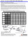
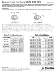
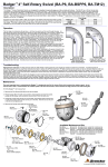
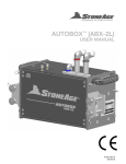
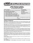
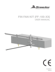
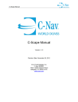
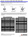
Banshee® Tube Spinner (BN9.5, BN13, BN18, BN24, BN33)
SAPATENTS.COM
The Banshees are self-rotating swivels designed for tube cleaning. The diameter of the tool and inlet nut connection
determine the model and part number. The tool can be used at operating pressures from 1000 psi to 22,000 psi,
depending on the inlet connection and head jetting.
Nozzle Heads:
Three standard head designs are available for most sizes. Refer to Table 2 for Head Pressure and Flow
Specifications.
85-105°
2X 145°
2X 135-145°
2X 90°
30°
30°
20°
15°
45°
POLISHER 042
60°
UNPLUGGER 043
UNIVERSAL 044
Each head is capable of a range of pressures and flows. The pull of the standard heads ranges from 3 to 5 pounds.
The nozzle heads are wear items that will need to be replaced after 20 to 60 hours, depending on water filtration and
operating pressure. The wrench flats provided on the Shaft, Head, Body & Nut should always be used when
maintaining these tools. Table 3 details the wrench size required for each tool part. These wrenches are available
from StoneAge.
Table 2- Head Options
Table 1- Tool Specifications
Part Number
Inlet Connection
Max Presure
BN9.5-P1
BN9.5-M7
BN9.5-MP4L
BN9.5-MP4R
1/16 NPT
M7-1.0
1/4-28 Left Hand
1/4-28 Right Hand
15kpsi / 1035 bar
22kpsi / 1500 bar
22kpsi / 1500 bar
22kpsi / 1500 bar
BN13-P2
BN13-BSPP2
BN13-MP4L
BN13-MP4R
BN13-MP6L
BN13-MP6R
1/8 NPT
1/8 BSPP
1/4-28 Left Hand
1/4-28 Right Hand
3/8-24 Left Hand
3/8-24 Right Hand
15kpsi / 1035 bar
18kpsi / 1250 bar
22kpsi / 1500 bar
22kpsi / 1500 bar
22kpsi / 1500 bar
22kpsi / 1500 bar
BN18-P4
1/4 NPT
BN18-BSPP4
1/4 BSPP
BN18-MP9L
9/16-18 Left Hand
BN18-MP9R
9/16-18 Right Hand
BN24-P6
3/8 NPT
3/8 BSPP
BN24-BSPP6
BN24-MP9L
9/16-18 Left Hand
BN24-MP9R
9/16-18 Right Hand
1/2 NPT
BN33-P8
BN33-BSPP8
1/2 BSPP
BN33-MP9 9/16 Medium Pressure
15kpsi / 1035 bar
20kpsi / 1400 bar
22kpsi / 1500 bar
22kpsi / 1500 bar
15kpsi / 1035 bar
22kpsi / 1500 bar
22kpsi / 1500 bar
22kpsi / 1500 bar
15kpsi / 1035 bar
22kpsi / 1500 bar
22kpsi / 1500 bar
Part
Pressure Range (psi)
Flow
BN9.5-A
-B
10,000 -15,000 psi
15,000 -22,000 psi
5-6 gpm
5-6 gpm
BN13 - A
-C
8,000 -15,000 psi
12,000 -22,000 psi
7-9 gpm
7-9 gpm
BN18 - A
-B
-C
-D
8,000 -15,000 psi
8,000 -15,000 psi
12,000 -22,000 psi
12,000 -22,000 psi
11-14 gpm
8-10 gpm
11-14 gpm
8-10 gpm
BN24 - A
-B
-C
-D
-E
-F
8,000 -15,000 psi
8,000 -15,000 psi
8,000 -15,000 psi
12,000 -22,000 psi
12,000 -22,000 psi
12,000 -22,000 psi
19-24 gpm
14-18 gpm
11-13 gpm
17-20 gpm
14-16 gpm
11-13 gpm
BN33 - A
-B
-C
-D
-E
-F
-G
-H
-I
8,000 - 15,000 psi
8,000 - 15,000 psi
8,000 - 15,000 psi
8,000 - 15,000 psi
8,000 - 15,000 psi
12,000 - 22,000 psi
12,000 - 22,000 psi
12,000 - 22,000 psi
12,000 - 22,000 psi
39-48 gpm
32-38 gpm
25-31 gpm
19-24 gpm
14-18 gpm
21-25 gpm
17-20 gpm
14-16 gpm
11-13 gpm
Caution!
Never use Pipe Wrenches or Pliers to install or
maintain the Banshee. After each use, always blow water out
of the tool and fill with light oil such as WD-40.
© 05/03/2013 StoneAge ®, All Rights Reserved
Banshee® Tube Spinner (BN9.5, BN13, BN18, BN24, BN33)
SAPATENTS.COM
Safe Practices for Operation and Maintenance of Banshee® Tools
This information is critical to ensure safe operation of the tool and to achieve maximum tool operational life. Tool
life can vary based on the type and frequency of cleaning operations, but improper maintenance can significantly
degrade the usable life of a tool. Most Banshee tool issues occurring within the expected reliable lifetime of the
Banshee result from users not adhering to the following recommended procedures.
Attention! Use the Right Tool for the Job
Use a correctly sized open end wrench to fit flats provided on the Inlet Nut when attaching tool to lance. Do not use
Pipe Wrench or Pliers with teeth as this can crush and/or crack the hardened steel body, leading to tool breakage in
operation. Recommended torque ranges and proper wrench sizes for tightening the heads to Banshee shafts are
shown in Table 3. All standard open end wrenches are available from StoneAge. Preset torque wrenches for Head
installation are also available from StoneAge.
Pressure Dump
The pressure dump mechanism is the most important safety device when flex lancing. The operator nearest the
nozzle should have control of the dump valve. If using multiple operators, each must have his own dump valve.
Hose
The high pressure hose should be as large as possible to minimize the pressure loss through the hose. Hose should
be inspected for excessive wear or damage prior to use. The high pressure hose and end fitting should be no larger
than the tool to be used on the end of it. There is an increased risk of hydraulic-ing when cleaning plugged tubes,
when using larger ends.
Stinger
A stinger is a rigid piece of pipe or tubing used between the end of the hose and the nozzle. It is typically 2 feet in
length and is primarily a safety device for hand flex lancing. When using stingers, the operator should be trained not
to use it as a pry-bar or to bang on the deposit, particularly with rotating tube nozzles. They may break or stop
rotating while being forced against the deposit. The coupling connecting the hose to the stinger should be of the
slim-line type and no larger in diameter than the nozzle body; a larger coupling diameter increases the chances of
material catching on the coupling and causing hydraulic-ing to occur.
Anti-Withdrawal Device
An anti-withdrawal device should be used when flex lancing. These devices provide a mechanical stop to prevent
the waterjet tool from exiting the tube and injuring the operator during cleaning operations.
Operation
We recommend that the entire system be flushed out before installing the Banshee on the end of the hose or
stinger. The swivels require a clean water supply for reliable operation; filtration of 25 micron or better is
recommended. Once the system is flushed, attach the Banshee and place it in an open tube while the operating
pressure is being set. When the tool is at operating pressure, the water exiting the tool through the leak paths will
keep external debris from entering the tool. If the tool is not under pressure, it should not be left inside a plugged
tube. Doing so could allow debris to enter and prevent rotation or cause damage to the tool. If the tool does not
rotate when the dump valve is closed, the operator should try closing the dump valve slowly a few times to build up
pressure slowly until normal operation is achieved. This also flushes debris out of the tool.
The drilled nozzle head will last between 20 and 60 hours. Worn jets decrease the cutting rate. The tool may begin
to hydraulic when cleaning plugged tubes. This occurs if the the jets are not effectively cutting the material into
smaller pieces. When using rotating nozzles in plugged tubes, do not jam the head into the deposit because this
will stop the rotation of the tool and impede the cutting ability. When the tool contacts the deposit, allow it to cut
away the material and advance at its own rate. If it stops advancing, pull back slightly on the hose to move the head
away from the deposit. This action also allows the jets to cut the deposit at different angles. The hose should be
gradually fed into and out of the tube, allowing time for the jets to do their work. Repeat this process until the tube is
unplugged.
When polishing tubes with scale, the tool has been observed passing through a 50 foot long scaled tube in 10
seconds. While this is sufficient when cleaning easy-to-remove deposits, we recommend feeding the tool through
the tube at a slower rate. This will ensure adequate cleaning. Unless the deposit is very easy to remove, this will
not completely remove the scale.
© 05/03/2013 StoneAge ®, All Rights Reserved
Banshee® Tube Spinner (BN9.5, BN13, BN18, BN24, BN33)
SAPATENTS.COM
Attention! Clean and Store the Tool Properly
Between jobs, the swivel should be blown out and filled with light oil. StoneAge recommends WD-40 to prevent
corrosion pitting. Pitting can cause premature tool failure due to cracking.
Maintenance
All sizes of the Banshee tool line have a tapered shaft that fits into a tapered body. Under operating conditions
these surfaces do not touch. Do not pull out on the head/shaft in order to rotate the tool, it will lock up. If this
happens, tap the head/shaft on a surface to knock it free. The operators should be cautioned not to pry sideways
on the tool. This may break the shaft just behind the head, particularly if a rigid stinger is being used in the inlet.
Check the nozzle orifices in the head for plugging; if one becomes plugged the swivel will likely not rotate. If this
does not solve the problem, the swivel should be disassembled and inspected. There are four small holes exiting
the tapered portion of the shaft; these should be checked for debris and cleaned out. Blow out the body and wipe
off the shaft to remove any debris.
Refer to Table 3 for recommended assembly torque ranges and proper wrench sizes.
Table 3- Recommended Torque Ranges and Required Wrench Sizes
PART
BN9.5
BN13
BN18
BN24
BN33
Shaft
Head
Body
Nut
Shaft
Head
Body
Nut
Shaft
Head
Body
Nut
Shaft
Head
Body
Nut
Shaft
Head
Body
Nut
WRENCH RECOMMENDED TORQUE RANGES (with anti-seize)
SIZE (in)
in-lbs
ft-lbs
N-m
3/16
5/16
11/32
5/16
13/64
3/8
7/16
7/16
5/16
9/16
9/16
5/8
1/2
13/16
13/16
13/16
9/16
1-1/8
1-1/8
1-1/8
36
40
3
3.3
4.1
4.5
194
216
16
18
22
24.4
63
70
5
5.8
7.1
7.9
270
300
23
25
30.5
33.9
180
200
15
16.7
20.3
22.6
540
600
45
50
61
67.8
432
480
36
40
48.8
54.2
756
840
63
70
85.4
94.9
486
540
41
45
54.9
61
1080
1200
90
100
122
135.6
BNxx 002 Inlet Nut
BNxx 001 Shaft
Head to Shaft torque
recommendationsee Table 3
BNxx 003 Body
Nut to Body torque
recommendationsee Table 3
Small holes in shaft
*BNxx is used to denote the
BN9.5, BN13, BN18, BN24 or BN33 tools
Head (see Head Options above)
Warning!
Use a correctly sized open end wrench to fit flats
provided on the Inlet Nut when attaching tool to lance. Do not use
Pipe Wrench or Pliers with teeth as this can crush and/or crack the
hardened steel body, leading to tool breakage in operation.
© 05/03/2013 StoneAge ®, All Rights Reserved