1
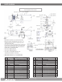
AUTOBOX® (ABX-2L-V2)
USER MANUAL
PL 602-V2 REV A
(10/2015)
TABLE OF CONTENTS
.MANUFACTURER’S INFORMATION.. . . . . . . . . . . . . . . . . . . . . . . . . . . . . . . . . . . . . . . . . . . . . . . . . . . . . . . . . . . . . . . . 3
SPECIFICATIONS. . . . . . . . . . . . . . . . . . . . . . . . . . . . . . . . . . . . . . . . . . . . . . . . . . . . . . . . . . . . . . . . . . . . . . . . . . . . . . . . . . . . . . . . . 3
DESCRIPTION OF EQUIPMENT AND INTENDED USE. . . . . . . . . . . . . . . . . . . . . . . . . . . . . . . . . . . . 3
KEY FEATURES. . . . . . . . . . . . . . . . . . . . . . . . . . . . . . . . . . . . . . . . . . . . . . . . . . . . . . . . . . . . . . . . . . . . . . . . . . . . . . . . . . . . . . . . . . . . 3
CE DECLARATION OF CONFORMITY. . . . . . . . . . . . . . . . . . . . . . . . . . . . . . . . . . . . . . . . . . . . . . . . . . . . . . . . . . . . 4
WARNING AND SAFETY INSTRUCTIONS. . . . . . . . . . . . . . . . . . . . . . . . . . . . . . . . . . . . . . . . . . . . . . . . . . . . . . . . 5
OPERATOR TRAINING. . . . . . . . . . . . . . . . . . . . . . . . . . . . . . . . . . . . . . . . . . . . . . . . . . . . . . . . . . . . . . . . . . . . . . . . . . . . . . . . . . 5
PERSONAL PROTECTIVE EQUIPMENT REQUIREMENTS.. . . . . . . . . . . . . . . . . . . . . . . . . . . . . . 5
SAFETY LABEL DEFINITIONS. . . . . . . . . . . . . . . . . . . . . . . . . . . . . . . . . . . . . . . . . . . . . . . . . . . . . . . . . . . . . . . . . . . . . . . 5
PRE-RUN SAFETY CHECK. . . . . . . . . . . . . . . . . . . . . . . . . . . . . . . . . . . . . . . . . . . . . . . . . . . . . . . . . . . . . . . . . . . . . . . . . . . 6
SYSTEM ASSEMBLY - OVERVIEW .. . . . . . . . . . . . . . . . . . . . . . . . . . . . . . . . . . . . . . . . . . . . . . . . . . . . . . . . . . . . . . . . . . 7
LIGHTWEIGHT POSITIONER - OVERVIEW . . . . . . . . . . . . . . . . . . . . . . . . . . . . . . . . . . . . . . . . . . . . . . . . . . . . . . 8
LIGHTWEIGHT POSITIONER CLAMP SELECTION.. . . . . . . . . . . . . . . . . . . . . . . . . . . . . . . . . . . . . . . . . 9
LIGHTWEIGHT POSITIONER SET-UP.. . . . . . . . . . . . . . . . . . . . . . . . . . . . . . . . . . . . . . . . . . . . . . . . . . . . . . . . . . . . 10
GUIDE ASSEMBLY - OVERVIEW . . . . . . . . . . . . . . . . . . . . . . . . . . . . . . . . . . . . . . . . . . . . . . . . . . . . . . . . . . . . . . . . . . . . . . 12
GUIDE ASSEMBLY SET-UP. . . . . . . . . . . . . . . . . . . . . . . . . . . . . . . . . . . . . . . . . . . . . . . . . . . . . . . . . . . . . . . . . . . . . . . . . . . 13
GUIDE ASSEMBLY TO LIGHTWEIGHT POSITIONER SET UP. . . . . . . . . . . . . . . . . . . . . . . . . . 14
AUTOBOX® (ABX-2L-V2) HOSE TRACTOR - OVERVIEW . . . . . . . . . . . . . . . . . . . . . . . . . . . . . . . . 15
AUTOBOX® (ABX-2L-V2) HOSE TRACTOR DOORS AND PINS. . . . . . . . . . . . . . . . . . . . . . . 16
AUTOBOX® (ABX-2L-V2) HOSE TRACTOR DRIVE ROLLERS. . . . . . . . . . . . . . . . . . . . . . . . . . 17
AUTOBOX® (ABX-2L-V2) HOSE TRACTOR TO GUIDE ASSEMBLY. . . . . . . . . . . . . . . . . . 18
CONTROL BOX - OVERVIEW. . . . . . . . . . . . . . . . . . . . . . . . . . . . . . . . . . . . . . . . . . . . . . . . . . . . . . . . . . . . . . . . . . . . . . . . . . . . 19
CONTROL BOX SET-UP.. . . . . . . . . . . . . . . . . . . . . . . . . . . . . . . . . . . . . . . . . . . . . . . . . . . . . . . . . . . . . . . . . . . . . . . . . . . . . . . 20
CONTROL BOX AIR SUPPLY FITTING. . . . . . . . . . . . . . . . . . . . . . . . . . . . . . . . . . . . . . . . . . . . . . . . . . . . . . . . . . . 21
CONTROL BOX TO AUTOBOX® (ABX-2L-V2) HOSE TRACTOR ASSEMBLY. . . . 22
OPERATION. . . . . . . . . . . . . . . . . . . . . . . . . . . . . . . . . . . . . . . . . . . . . . . . . . . . . . . . . . . . . . . . . . . . . . . . . . . . . . . . . . . . . . . . . . . . . . . . . . . . . . 23
COLLET INSERTION, HOSE, AND HOSE STOP INSTALLATION. . . . . . . . . . . . . . . . . . . . . . 23
CONTROL BOX, TEST RUN, AND RUN PROCEDURES. . . . . . . . . . . . . . . . . . . . . . . . . . . . . . . . . . 24
HIGH PRESSURE HOSE AND HOSE CLAMP.. . . . . . . . . . . . . . . . . . . . . . . . . . . . . . . . . . . . . . . . . . . . . . . . 25
STORAGE, TRANSPORTATION, AND HANDLING. . . . . . . . . . . . . . . . . . . . . . . . . . . . . . . . . . . . . . . . . . . . 25
MAINTENANCE. . . . . . . . . . . . . . . . . . . . . . . . . . . . . . . . . . . . . . . . . . . . . . . . . . . . . . . . . . . . . . . . . . . . . . . . . . . . . . . . . . . . . . . . . . . . . . . . . 26
PARTS DIAGRAMS. . . . . . . . . . . . . . . . . . . . . . . . . . . . . . . . . . . . . . . . . . . . . . . . . . . . . . . . . . . . . . . . . . . . . . . . . . . . . . . . . . . . . . . . . . . . 27
TERMS AND CONDITIONS. . . . . . . . . . . . . . . . . . . . . . . . . . . . . . . . . . . . . . . . . . . . . . . . . . . . . . . . . . . . . . . . . . . . . . . . . . . . . . . 33
2
866-795-1586 • WWW.STONEAGETOOLS.COM
MANUFACTURER’S INFORMATION
StoneAge Inc.
Andrew Birt Consulting Ltd.
466 S. Skylane Drive
UK
Durango, CO 81303, USA
Phone: 970-259-2869
Toll Free: 866-795-1586
www.stoneagetools.com
This manual must be used in accordance with all applicable national laws. The manual shall be regarded as a part of the machine
and shall be kept for reference until the final dismantling of the machine, as defined by applicable national law(s).
SPECIFICATIONS
AUTOBOX® (ABX-2L-V2) Hose Tractor Weight:
AUTOBOX® (ABX-2L-V2) Hose Tractor Size:
42 lbs (19.05 kg) (AUTOBOX® (ABX-2L-V2) box only)
7.2 in. Wide x 8.3 in. Tall x 16.7 in. Long
(183 mm Wide x 211 mm Tall x 424 mm Long)
3.0 ft/sec (914 mm/sec)
0.2 ft/sec (61 mm/sec)
60 lbs (30 lbs per lance) (27.2 kg, 13.6 kg per lance)
10 lbs (5 lbs per lance) (4.5 kg), (2.25 kg per lance)
18 in. (457 mm)
120 lbs (54.4 kg)
(Includes 6ft rails, horiz., vert., and idler carriage, and 4 clamps)
10 lbs (4.5 kg)
5/8-2.4 in. (16 mm- 61 mm)
43 lbs (19.5 kg) (Includes Control Box, FRL, and stand)
140 psi (0.97 MPa)
100 psi (0.70 MPa)
-20 °F to 140 °F (-29 °C to 60 °C)
Maximum Feed Rate:
Minimum Feed Rate:
Maximum Push/Pull Force:
Minimum Push/Pull Force:
Manway Access:
Lightweight Positioner Weight:
Guide Assembly Weight:
Pitch Adjustment Range:
Control Box Weight:
Maximum Air Supply Pressure:
System Operating Pressure:
Recommended Operational Temperature Range:
DESCRIPTION OF EQUIPMENT AND
INTENDED USE
KEY FEATURES:
The AUTOBOX® (ABX-2L-V2) System consists of the AUTOBOX®
(ABX-2L-V2) Hose Tractor, Control Box, Guide Assembly, and
Lightweight Positioner. This system was developed for “Hands Free”
heat exchanger tube cleaning applications. It is recommended to be
used with StoneAge’s Banshee line of self-rotary waterblast tools.
The AUTOBOX® (ABX-2L-V2) System was designed to accommodate
two simultaneous flex lances ranging in size from 3/2 to 8/4 matched
with the appropriate BN9.5, BN13, BN15, or BN18 size Banshees.
The AUTOBOX® (ABX-2L-V2) Hose Tractor utilizes six synchronized
drive rollers to control the rate at which the hose and Banshee tools
are advanced or retracted within the exchanger tubes.
The Guide Assembly provides anti-withdrawal protection, and precise
tube pitch adjustment. The Lightweight Positioner can be mounted to
a variety of heat exchanger tube bundles and has pneumatic powered
horizontal and vertical drives.
The Control Box is small and lightweight with an emphasis on
ergonomics. The AUTOBOX® (ABX-2L-V2) system was designed with
simplicity, safety, lightweight components, durability, and reliability in
mind. It can be easily carried to the job site and setup in minutes.
Lightweight Positioner
• Modular, lightweight design
• Quick install drive carriages
• Utilizes 2.5 in. (6 mm) box rail
• Stainless Steel air motors
• Variety of clamp and bolt-on attachment options are available
Guide Assembly
• Compact and lightweight design
• Turn knob control provides precise pitch adjustment
• Quick change guide tubes
• 17-4 SS hose stop collets
AUTOBOX® (ABX-2L-V2) Hose Tractor
• Six powered drive rollers ensure traction in all
operating conditions
• Quick change drive rollers (three sizes).
• Lightweight and compact design
• Can be used in dual or single lance applications
• Quick pin attachment to guide assembly
• Hinged side doors for easy access to rollers and
drive components
• Independent forward/reverse speed controls
Control Box
• Small, lightweight, ergonomic design that includes a
portable stand and filter-regulator-lubricator assembly
• Tractor controls: forward/reverse hose feed and clamp pressure
• Positioner controls: left/right and up/down
• Pneumatic dump control switch
866-795-1586 • WWW.STONEAGETOOLS.COM
3
CE DECLARATION OF CONFORMITY
In accordance with BS EN ISO/IEC 17050-1:2010
We:
StoneAge, Inc. 466 South Skylane Drive Durango, CO 81303, USA
Declare that:
Equipment: AUTOBOX® Hose Tractor
Model name: ABX-2L-V2 Is in accordance with the following Directives:
2006/42/EC Conforms to the Essential Health and Safety Requirements of the Machinery Directive
Has been designed and manufactured to the relevant parts of the following specifications:
EN ISO 12100:2010
Safety of machinery - General principles for design - Risk assessment and risk reduction
I hereby declare that the equipment named above has been tested and found to comply with the relevant sections of the
above referenced specifications and directives.
Signed ______________________________________________________
Date _
07/01/2015__________
Andrew Birt
Independent Dealer Manager
StoneAge, Inc., Worcester, UK
The technical file for the AUTOBOX® (ABX-2L-V2) User Manual is maintained at: StoneAge, Inc. 466 South Skylane Drive,
Durango, CO 81303, USA
4
866-795-1586 • WWW.STONEAGETOOLS.COM
WARNING AND SAFETY INSTRUCTIONS
OPERATOR TRAINING
Managers, Supervisors, and Operators MUST be trained in Health
and Safety Awareness of High-pressure Water Jetting and hold
a copy the Water Jetting Association (WJA) Code of Practice, or
equivalent (see www.waterjetting.org.uk).
Operators MUST be trained to identify and understand all applicable
standards for the equipment supplied. Operators should be trained
in manual handling techniques to prevent bodily injury.
StoneAge has designed and manufactured this equipment
considering all hazards associated with its operation. StoneAge
assessed these risks and incorporated safety features in the design.
StoneAge WILL NOT accept responsibility for the results of misuse.
Operators MUST read, understand, and follow the Operational and
Training Requirements (Section 7.0) of WJTA-IMCA’s Recommended
Practices For The Use Of High-pressure Water jetting Equipment, or
equivalent.
Operators MUST read, understand, and follow the Warnings,
Safety Information, Assembly, Installation, Connection, Operation,
Transport, Handling, Storage, and Maintenance Instructions detailed
in this manual.
The risk assessment MUST consider potential material or substance
hazards including:
• • IT IS THE RESPONSIBILTY OF THE INSTALLER/OPERATOR to
conduct a job specific risk assessment prior to use. Job specific risk
assessment MUST be repeated for each different set up, material,
and location.
• The risk assessment MUST conform to the Health and Safety at
Work Act 1974 and other relevant Health and Safety legislation.
• • • • • • • • • PERSONAL PROTECTIVE EQUIPMENT REQUIREMENTS
Use of Personal Protective Equipment (PPE) is dependent on
the working pressure of water and the cleaning application.
Managers, Supervisors, and Operators MUST carry out a job
specific risk assessment to define the exact requirements for PPE.
See Protective Equipment for Personnel (Section 6) of WJTAIMCA’s Recommended Practices For The Use Of High-pressure
Waterjetting Equipment for additional information.
Hygiene - Operators are advised to wash thoroughly after all
waterjetting operations to remove any waterblast residue which may
contain traces of harmful substances.
First aid provision - users MUST be provided with suitable first aid
facilities at the operation site.
Aerosols
Biological and microbiological (viral or bacterial) agents
Combustible materials
Dusts
Explosion
Fibers
Flammable substances
Fluids
Fumes
Gases
Mists
Oxidizing Agents
PPE may include:
• Eye protection: Full face visor
• Foot protection: Kevlar® brand or steel toe capped,
waterproof, non-slip safety boots
• Hand protection: Waterproof gloves
• Ear protection: Ear protection for a minimum of 85 dBA
• Head protection: Hard hat that accepts a full face visor and
ear protection
• Body protection: Multi-layer waterproof clothing approved for
waterjetting
• Hose protection: Hose shroud
• Respiratory protection: May be required; refer to job specific
risk assessment
SAFETY LABEL DEFINITIONS
The AUTOBOX® (ABX-2L-V2) Hose Tractor
has the potential to cause serious injury
if fingers, hair, or clothing become caught
between the
hose rollers or drive belts.
DO NOT OPERATE WITH THE DOORS
OPEN. ENSURE THAT ALL FOUR
DOOR PINS ARE SECURED PRIOR TO
OPERATION.
Maximum operating air pressure is
100 psi (0.7 MPa). Never exceed
140 psi (0.97 MPa) supply pressure.
Exceeding 140 psi (0.97 MPa) supply
pressure may result in injury to the
Operator and/or damage to the
equipment.
866-795-1586 • WWW.STONEAGETOOLS.COM
5
WARNING AND SAFETY INSTRUCTIONS
WARNING
Operations with this equipment can be potentially hazardous.
Caution MUST be exercised prior to and during machine and water
jet tool use. Please read and follow all of these instructions, in addition
to the guidelines in the WJTA Recommended Practices handbook,
available online at www.wjta.org. Deviating from safety instructions
and recommended practices can lead to severe injury and/or death.
Refer to WJTA-IMCA’s, Recommended Practices For The Use Of
High pressure Waterjetting Equipment and/or The Water Jetting
Association’s, WJA Code of Practice for additional safety information.
• Complete a job specific risk assessment and act on the resulting
actions.
• Adhere to all site specific safety procedures.
• Ensure the waterblasting zone is properly barricaded and that
warning signs are posted.
• Ensure the work place is free of unnecessary objects (e.g. loose
parts, hoses, tools).
• Ensure all Operators are using the correct Personal Protective
Equipment (PPE).
• Do not exceed the maximum operating pressure specified for
any component in a system.
• The immediate work area MUST be marked off to keep out
untrained persons.
• Inspect the equipment for visible signs of deterioration,
damage, and improper assembly. Do not operate if damaged,
until repaired.
• Make sure all threaded connections are tight and free of leaks.
• Check that the air hoses are properly connected and tight.
• Users of the AUTOBOX® (ABX-2L-V2) Hose Tractor MUST be
trained and/or experienced in the use and application of high
pressure technology and cleaning, as well as all associated
safety measures, according to the WJTA Recommended
Practices for the use of High pressure Water jetting Equipment.
• Check all hoses and accessories for damage prior to use. Do
not use damaged items. Only high quality hoses intended for
waterblast applications should be used as high pressure hoses.
• Check all high pressure threaded connections for tightness.
• 6
PRE-RUN SAFETY CHECK
An anti-withdrawal device (back-out preventer) MUST be used
at all times. The back-out prevention device is the Hose Stop
Collet located within the Hose Guide Assembly. StoneAge
offers several different size Hose Stop Collets. The Collet Size
Reference guide is located on the Hose Guide Assembly.
• The Control Box should be located in a safe location where the
Operator has good visibility of the tool entering the exchanger
tubes. The AUTOBOX® (ABX-2L-V2) Hose Tractor and Control
Box MUST be supervised at all times and should never be left
unattended.
• Do not fully release the hose clamp (decreasing pressure to
zero) during operation, or the AUTOBOX® (ABX-2L-V2) Hose
Tractor will release the hose and may create a dangerous
runaway hose condition, which can result in severe injury and/
or death.
• Always de-energize the system before opening the door to
service or replace any parts. Failure to do so can result in severe
injury and/or death.
• When moving the AUTOBOX® (ABX-2L-V2) Hose Tractor lift with
care to prevent bodily injury.
• Do not operate the AUTOBOX® (ABX-2L-V2) Hose Tractor while
either side door is open.
• **Ensure
that an anti-withdrawal device (back-out
preventer), whip checks (hose whips), and all other
applicable safety devices are installed and set-up
properly.**
• Ensure the doors of the AUTOBOX® (ABX-2L-V2) Hose Tractor
are closed and securely latched.
• Test the Control Box before operating the AUTOBOX® (ABX2L-V2) Hose Tractor with high pressure water to verify the control
valves move the hose in the intended direction, and that the high
pressure dump valve and hose clamp are working properly.
• Ensure that Operators never connect, disconnect, or tighten
hoses, adapters, or accessories with the high pressure water
pump unit running.
• Ensure no personnel are in the hydroblasting zone.
866-795-1586 • WWW.STONEAGETOOLS.COM
SYSTEM ASSEMBLY - OVERVIEW
LIGHTWEIGHT POSITIONER, GUIDE ASSEMBLY,
AUTOBOX® (ABX-2L-V2) HOSE TRACTOR AND CONTROL BOX SYSTEM ASSEMBLY
LIGHTWEIGHT POSITIONER
(SEE PAGES 8, 9, 10, 11)
CONTROL BOX
(SEE PAGES 19, 20, 21, 22)
AUTOBOX® (ABX-2L-V2)
HOSE TRACTOR
(SEE PAGES 15, 16, 17, 18)
HOSES RUN TO
HIGH PRESSURE
WATER SUPPLY
GUIDE ASSEMBLY
(SEE PAGES 12, 13, 14)
NOTE: Heat exchanger tube
bundle face, shown for
graphic representation only.
Not included in assembly.
866-795-1586 • WWW.STONEAGETOOLS.COM
7
LIGHTWEIGHT POSITIONER - OVERVIEW
LIGHTWEIGHT POSITIONER
RAIL STOP ASSEMBLIES
RAIL EXTENSIONS
(2,4, OR 6 FT LENGTHS)
(610 mm, 1219 mm, OR 1829 mm)
HORIZONTAL
DRIVE
ASSEMBLY
VERTICAL
SLOTTED
RAIL
POSITIONER
CONTROL LINE
ASSEMBLY
HORIZONTAL
SLOTTED RAIL
25 FT / 7620 mm
STANDARD
LENGTH
CLAMP TYPES
(LWP 625 KIT
INCLUDES ALL KITS
SHOWN HERE)
VERTICAL
DRIVE
ASSEMBLY
NON-SLOTTED RAIL
SLOTTED
QUICK CLAMP
(LWP 620 KIT
CONTAINS 4)
QUICK CLAMP
(LWP 621 KIT
CONTAINS 4)
RAIL STOP
ASSEMBLY
8
BLANK HORIZONTAL
ASSEMBLY
866-795-1586 • WWW.STONEAGETOOLS.COM
PLATE CLAMP
(LWP 622 KIT
CONTAINS 2)
LIGHTWEIGHT POSITIONER CLAMP SELECTION
CLAMP SELECTION
Is dependent upon the heat exchanger geometry, bolt holes, hole spacing,
and flange accessibility.
CLAMP TYPES
(LWP 625 KIT
INCLUDES ALL KITS
SHOWN HERE)
QUICK CLAMPS
Use if heat exchanger flange provides a robust clamping surface or if
flange holes are inaccessible. Align clamps on the surface of the flange to
maximize flange engagement to clamps. (Figure 2)
SLOTTED QUICK AND PLATE CLAMPS
Use if heat exchanger flange has bolt holes that are easily accessible.
Use quick clamps or plate clamps, depending on the spacing of the hole
pattern. (Figures 1 & 3)
SLOTTED
QUICK CLAMP
(LWP 620 KIT
CONTAINS 4)
QUICK CLAMP
(LWP 621 KIT
CONTAINS 4)
FIGURE 1
FIGURE 2
PLATE CLAMP
(LWP 622 KIT
CONTAINS 2)
FIGURE 3
866-795-1586 • WWW.STONEAGETOOLS.COM
9
LIGHTWEIGHT POSITIONER SET-UP
LIGHTWEIGHT POSITIONER STEP BY STEP SET-UP
1. Mount the appropriate frame Positioner Clamps to the tube
bundle as shown on the previous page. (Shown in Figure 1 with
Slotted Quick Clamps) Positioner Clamps should be aligned
horizontally with the direction of the tube rows. (Figure 1)
NOTE: Heat exchanger tube bundle face, shown for graphic
representation only. Not included in assembly.
FIGURE 1
2. Insert the Top Rail (slots facing out) into the upper mounting
brackets. If the rail is not closely aligned with the tube rows,
loosen one of the upper mounting brackets and adjust until
the top rail is parallel with the horizontal tube rows. Tighten the
clamps securing the rail to the mounting brackets. Ensure upper
mounting brackets are securely clamped or bolted to the tube
bundle flange. (Figure 2)
FIGURE 2
3. Insert the Lower Rail (non-slotted) into the lower mounting
brackets. It is not critical that this rail is aligned as precisely as
the top rail, but it should be close to parallel with the top rail
for best performance. Tighten the clamps securing the rail to
the mounting brackets. Ensure lower mounting brackets are
securely clamped or bolted to the tube bundle flange. (Figure 3)
FIGURE 3
4. Loosen the Quick Adjust Handle and pull the gearbox away
from the carriage plate. This will allow the Horizontal Drive
Carriage to slide onto the rail without pneumatic power, to
rotate the drive. Center the carriage on the top rail and push
the gearbox back toward the carriage plate. This will engage
the gear into the rail slots. Verify the gear is engaging the slots
correctly and tighten the quick adjust handle. (Figure 4)
FIGURE 4
10
866-795-1586 • WWW.STONEAGETOOLS.COM
LIGHTWEIGHT POSITIONER SET-UP
5. Slide the Idler Carriage onto the Lower Non-Slotted Rail.
(Figure 5)
FIGURE 5
6. Loosen the Large Adjustable Handle for the Vertical Rail
Clamp. Align the Idler Carriage with the vertical rail clamp on
the horizontal carriage. Install the Vertical Rail with (slots
facing out) down through the horizontal carriage clamp
and between the rollers on the idler carriage. Adjust the
position of the vertical rail as required and secure the clamp
on the horizontal carriage by tightening the large adjustable
handle. (Figure 6)
FIGURE 6
7. Loosen the Quick Adjust Handle and pull the gearbox
away from the carriage plate. This will allow the Vertical
Drive Carriage to slide onto the rail without pneumatic
power to rotate the drive. Center the carriage on the vertical
rail and push the gearbox back toward the carriage plate.
This will engage the gear into the rail slots. Verify the gear
is engaging the slots correctly and tighten the quick adjust
handle. (Figure 7)
FIGURE 7
8. Install the four Rail Stops at both ends of the top, slotted,
horizontal rail, and both ends of the vertical slotted rail.
(Figure 8)
NOTE: Verify the mounting brackets and rail clamps are
securely tightened, and the drive carriages are securely
engaged, and the adjustable handles are tightened.
Never loosen the vertical gearbox once the guide
assembly and tractor are installed, as it may result in the
carriage falling vertically down. This may cause damage
to the equipment and/or injury.
FIGURE 8
866-795-1586 • WWW.STONEAGETOOLS.COM
11
GUIDE ASSEMBLY - OVERVIEW
GUIDE ASSEMBLY
GUIDE TUBES
(MULTIPLE SIZES
AVAILABLE)
HOUSING
TUBE CLAMP
GUIDE TUBE
ADAPTER SCREWS
COLLET REFERENCE
GUIDE
COLLET
(MULTIPLE SIZES
AVAILABLE)
MOUNTING
BRACKET
PITCH ADJUST KNOB
QUICK RELEASE PIN
HOSE STOP CLAMPS
(MULTIPLE SIZES AVAILABLE)
12
866-795-1586 • WWW.STONEAGETOOLS.COM
GUIDE ASSEMBLY SET-UP
GUIDE ASSEMBLY
1. Select the appropriate Guide Tube size and length for the
application. The length of the Guide Tubes for an exchanger
bundle with no channel head is 12.5 in. (318 mm). The guide
tube assembly has approximately 5 in. (127 mm) of adjustment.
A deeper channel head will require extended Guide Tubes.
The depth of the channel head added to the 12.5 in. (318 mm)
length will give the desired tube length. Longer guide tubes
are available if required for use with channel heads. Note: The
Banshee tool should not have excessive clearance if the correct
length Guide Tube size is used.
WARNING
Appropriate size Collet selection is CRITICAL to ensuring
proper backout prevention of the tool.
*NOTE: BN9.5 guide tubes ( Ø.625 in. / 6 mm O.D.) require
StoneAge (SA) PART NUMBER
GUIDE TUBE REFERENCE CHART
SA PART NUMBER
2. To remove the existing Guide Tubes, loosen the Tube Clamp
Bolt and the two 3/16 in. Socket Head Cap Screws (SHCS)
located on top of the Guide Assembly. After selecting the
appropriate Guide Tubes, install the Guide Tubes into the Guide
Assembly.
3. Secure the Guide Tubes by tightening the two 3/16 in. SHCS.
an ABX 114 adapter. BN18 guide tubes require an ABX 124
to be installed into the Guide Assembly.
SA TOOL
INSIDE DIAMETER, LENGTH
ABX 115-12
*BN9.5
.459 in / 12 mm, 12.5 in. / 318 mm
ABX 115-36
*BN9.5
.459 in / 12 mm, 36 in. / 914 mm
SA PART NUMBER
COLLET SIZE
ABX 116-12
BN13
.546 in / 14 mm, 12.5 in. / 318 mm
ABX 121-297
.297 in. / 8 mm
ABX 116-36
BN13
.546 in / 14 mm, 36 in. / 914 mm
ABX 121-328
.328 in. / 8 mm
ABX 117-12
BN15
.674 in / 17 mm, 12.5 in. / 318 mm
ABX 121-406
.406 in. / 10 mm
ABX 117-36
BN15
.674 in / 17 mm, 36 in. / 914 mm
ABX 121-438
.438 in. / 11 mm
ABX 119-12
*BN18
.745 in / 19 mm, 12.5 in. / 318 mm
ABX 121-460
.460 in. / 12 mm
ABX 119-36
*BN18
.745 in / 19 mm, 36 in. / 914 mm
ABX 121-484
.484 in. / 12 mm
ABX 121-516
.516 in. / 13 mm
StoneAge (SA) PART NUMBER
HOSE STOP CLAMP REFERENCE CHART
SA PART
NUMBER
HOSE DIAMETER
HS 121-27-34
.27-.34 in. / 7-9 mm
HS 121-34-42
.34-.42 in. / 9-11 mm
HS 121-42-50
.42-.50 in. / 11-13 mm
HS 121-50-56
.50-.56 in. / 13-14 mm
HS 121-56-61
.56-.61 / 14-16 mm
3
StoneAge (SA) PART NUMBER
COLLET REFERENCE CHART
ABX 121-547
.547in. / 14 mm
ABX 121-594
.594 in. / 15 mm
ABX 121-625
.625 in. / 16 mm
1
2
866-795-1586 • WWW.STONEAGETOOLS.COM
13
GUIDE ASSEMBLY TO LIGHTWEIGHT POSITIONER SET UP
ATTACH GUIDE ASSEMBLY TO LIGHTWEIGHT POSITIONER
1. Using a 9/16 in. wrench, loosen all four rail clamp bolts located on the vertical carriage. Install the Guide Assembly into the rail
clamps and adjust position until the Guide Tubes are approximately 1/2 in. (13 mm) away from the tube sheet face. Tighten the
four rail clamp bolts.
2. Turn the pitch adjustment knob until the guide tubes are at the same pitch as the tubes in the bundle. Adjust the Tube Clamp
Bolt until the Guide Tubes are resting in the bottom of the “V” blocks. Make any fine adjustment to the Guide Tube pitch if
required and tighten the Tube Clamp Bolt.
NOTE: Over-tightening the Tube Clamp may damage thin wall guide tubes.
1
2
ABX 114 ADAPTER FOR BN9.5
( Ø.625 in. / 6 mm O.D.)
Guide Tubes
ABX 124 ADAPTER FOR BN18
( Ø.875 in. / 22 mm O.D.)
Guide Tubes
NOTE:
Adjust position until
the Guide Tubes are
approximately 1/2 in.
(13 mm) away from the
tube sheet face.
14
866-795-1586 • WWW.STONEAGETOOLS.COM
ABX-2L HOSE TRACTOR - OVERVIEW
AUTOBOX® (ABX-2L-V2) HOSE TRACTOR
COLOR CODED
JIC FITTINGS
WITH DUST CAPS
HANDLE
DOOR PIN
FORWARD
AND REVERSE
SPEED
CONTROLS
MOUNTING
BRACKET
MOUNTING
BRACKET
QUICK
RELEASE
PIN
DRIVE ROLLERS
DOOR
QUICK
RELEASE
PINS
MOUNTING
BRACKET
FOR GUIDE
ASSEMBLY
SERIAL
NUMBER
PLATE
PNEUMATIC SUPPLY LINES
25 FT / 7620 mm
866-795-1586 • WWW.STONEAGETOOLS.COM
15
ABX-2L HOSE TRACTOR - DOORS AND PINS
DOOR
Always run the AUTOBOX® (ABX-2L-V2) Hose Tractor with the doors closed and locked.
DOOR PIN
The Door Pin is a spring plunger with a pull ring. To unlock the door, pull and twist the pull
ring, then release it so that it is no longer in the groove. Close the door by raising it into
position. To lock the door, pull and twist the pull ring, then release it into the groove of the pin.
UNLOCKED
NOTE: Make sure to lock both doors on each side of the Hose Tractor before operating
AUTOBOX® (ABX-2L-V2) Hose Tractor.
OPEN DOOR
POSITION
LOCKED
DOOR
PIN
DOOR
PINS
CLOSED DOOR
POSITION
16
866-795-1586 • WWW.STONEAGETOOLS.COM
ABX-2L HOSE TRACTOR - DRIVE ROLLERS
WARNING
Always de-energize the system before servicing or replacing any parts. Failure to do so can result in severe injury and/or death.
Keep hands, hair, and clothing clear of rotating parts.
TO REPLACE THE DRIVE ROLLERS:
1. Select the correct roller size for the particular hose being used:
• ABX 271 (DARK GRAY/BLACK) rollers should be used with 5 mm and 6 mm I.D. hoses.
The O.D. range for the ABX 271 roller is .44-.50 in (11 mm - 13 mm)
• ABX 272 (ORANGE) rollers should be used with 3 mm and 4 mm I.D. hoses.
The O.D. range for the ABX 272 is .27-.41 in (7 mm - 10 mm)
• ABX 273 (BLUE) rollers should be used with 8 mm I.D. hoses.
The O.D. range for the ABX 273 is .52-.61 in (13 mm - 16 mm)
2. Slowly run the Drive Rollers in order to orient the key ways of the Drive Rollers upward and the spring plungers downward.
NOTE: Rollers should be removed with the keyway facing up to prevent losing keys.
3. Use a small common screwdriver or similar tool to depress the ball spring plunger, and pull the rollers straight out from the shafts.
4. Prior to reinstalling the Drive Rollers onto the shafts, apply a liberal coat of Anti-seize to the shaft OD and keys.
We recommend Mariners Choice Never-Seez®.
5. Install the Drive Rollers by sliding into place until the spring plungers snap out.
NOTE: Drive Rollers should be installed with the keyway facing up to prevent losing keys.
6. Once the correct Drive rollers are installed, close and lock the doors. The Hose Tractor can now be installed onto the Guide Assembly.
ABX 271 (DARK GRAY/BLACK)
ABX 273 (BLUE)
ABX 272 (ORANGE)
KEY WAY
SPRING PLUNGER
ORIENTATION
DRIVE
ROLLERS (X6)
866-795-1586 • WWW.STONEAGETOOLS.COM
17
ABX-2L HOSE TRACTOR TO GUIDE ASSEMBLY
ATTACH AUTOBOX® (ABX-2L-V2) HOSE TRACTOR TO GUIDE ASSEMBLY
1. Remove the lower quick release pin from the AUTOBOX® (ABX-2L-V2) Hose Tractor.
2. Slide the mounting bracket over the block on the Guide Assembly and lay the pin onto the top slot on the Guide Assembly block.
3. Install the lower pin through the mounting bracket on the Hose Tractor and the block on the Guide Assembly.
2
3
1
The tractor is now
securely mounted to the
Guide Assembly
18
866-795-1586 • WWW.STONEAGETOOLS.COM
CONTROL BOX - OVERVIEW
CONTROL BOX
TOP VIEW
MOMENTARY
PNEUMATIC
DUMP CONTROL
HOSE FEED
LEVER
HOSE CLAMP
PRESSURE REGULATOR
HOSE CLAMP
PRESSURE GAUGE
POSITIONER
CONTROLS
CONTROL BOX
CONTROL BOX
REAR VIEW
FRONT VIEW
POLE MOUNT
MAIN BOX
FRAME
WITH THUMB SCREW
1/4” (6 mm) PUSH CONNECT
PNEUMATIC DUMP
VERTICAL
CONTROL FITTING
POSITIONER
FITTINGS
WITH DUST CAPS
PRESSURE
REGULATOR
FILTER,
REGULATOR,
LUBRICATOR
INLET AIR
FITTING
TRIPOD
LEGS
INLINE OILER
FEED
ADJUSTMENT
AIR SUPPLY
FITTING
COLOR CODED
JIC FITTINGS
WITH DUST CAP
WITH DUST CAPS
HORIZONTAL
POSITIONER
FITTINGS
WITH DUST CAPS
866-795-1586 • WWW.STONEAGETOOLS.COM
COLOR CODED
JIC FITTING
WITH DUST CAP
19
CONTROL BOX SET-UP
ASSEMBLE CONTROL BOX, FRL, AND TRIPOD BASE
1. Setup the tripod base in a location with good visibility to the
bundle face, but at a safe distance away from waterblast zone.
2. Slide the vertical tube into the tripod base. Secure with the
supplied thumbscrew knob. Note: The vertical tube has a hole
through one wall that the thumbscrew must engage.
4. Slide the Control Box over the vertical tube. The Control Box
has a stop that keeps it located at the top of the vertical tube.
Secure with the supplied thumbscrew knob.
5. Install and tighten the short 1/2 in. (13 mm) I.D. hose between
the FRL and the Control Box.
3. Slide the Filter, Regulator, Lubricator (FRL) assembly over the
vertical tube down to the tripod base. Secure with the supplied
thumbscrew knob.
Note: The vertical tube has a hole through one wall that
the thumbscrew must engage.
FILTER, REGULATOR,
LUBRICATOR, ASSEMBLY
(FRL)
THUMBSCREW
KNOB
(ALIGN WITH
PRE-DRILLED
HOLE ON
TUBE INSERT)
4
3
2
5
1
THUMBSCREW
KNOB
(ALIGN WITH
PRE-DRILLED
HOLE ON
TUBE INSERT)
TUBE
INSERT
THUMBSCREW
KNOB
20
866-795-1586 • WWW.STONEAGETOOLS.COM
CONTROL BOX AIR SUPPLY FITTING
WARNING
AIR SUPPLY AND LUBRICATOR SETTING
1.The Control Box is supplied with a twist claw style inlet
coupling (Chicago style) located on the side of the FRL
Assembly. Connect a compatible compressed air line (not
included) according to the Manufacturer’s instructions. If
another pneumatic connection is preferred, this fitting can
be removed and any male 1/2 in (13 mm) NPT fitting may
be used.
Maximum operating air pressure is 100 psi (0.7 MPa). Never
exceed 140 psi (0.97 MPa) supply pressure. Exceeding 140 psi
(0.97 MPa) supply pressure may result in injury to the Operator
and/or damage to the equipment.
2.Using the regulator adjust the operating air pressure to 100
psi (0.7 MPa) for the application.
AIR SUPPLY FITTING
A universal AIR SUPPLY FITTING (Chicago style) is located on the
FRL. Connect a compatible compressed air line (not included) according
to the Manufacturer’s instructions. If another pneumatic connection is
preferred, this fitting can be removed and any male ½ in (13 mm) NPT
fitting may be used.
ADJUST INLINE OILER
TO FEED 1 DROP OF OIL
EVERY 30-60 SECONDS
FOR HIGH SPEED OR
CONTINUOUS DUTY
USAGE
PNEUMATIC DUMP CONTROL FITTING AND LINE
A MOMENTARY PNEUMATIC DUMP CONTROL is located on the
Control Box panel and can be set up to control an air actuated dump valve.
To utilize the toggle, the end user will need to install 1/4 in. (6 mm) O.D.
nylon tubing (not included) between the PNEUMATIC DUMP CONTROL
FITTING and the pneumatic dump valve.
PNEUMATIC DUMP
CONTROL FITTING
¼ IN OD TUBING
(NOT INCLUDED)
CONTROL BOX REAR VIEW
866-795-1586 • WWW.STONEAGETOOLS.COM
21
CONTROL BOX TO AUTOBOX® (ABX-2L-V2) HOSE TRACTOR ASSEMBLY
PNEUMATIC SUPPLY LINE CONNECTIONS
1. Remove the dust caps from the Joint Industry Council (JIC)
fittings of the Control Box and the AUTOBOX® (ABX-2L-V2)
Hose Tractor.
2. Connect the AUTOBOX (ABX-2L-V2) Hose Tractor to the
Control Box with two 1/2 in. (13 mm) JIC hoses and one 1/4
in. (6 mm) JIC hose. Verify the Control Box rotates the rollers
in the appropriate direction and that the clamp functions
correctly.
®
4. Connect the vertical positioner drive air motor to the Control
Box with two 1/4 in. (6 mm) JIC hoses. Verify the Control
Box moves the vertical carriage in the appropriate direction.
5. Test the Control Box before operating the AUTOBOX® (ABX2L-V2) Hose Tractor with high pressure water to verify the
control valves move the hose in the intended direction, and
that the dump valve is working properly.
3. Connect the horizontal positioner drive air motor to the
Control Box with two 1/4 in. (6 mm) JIC hoses. Verify the
Control Box moves the horizontal carriage in the appropriate
direction.
CLAMP
REVERSE
LEFT
UP
RIGHT
DOWN
FORWARD
Note: The 4 Positioner control lines are not color
coded. Colors are shown in manual for clarity.
3
REAR VIEW
4
2
22
866-795-1586 • WWW.STONEAGETOOLS.COM
OPERATION
COLLET INSERTION, HOSE, AND HOSE STOP INSTALLATION
1. Remove Quick Release Pin and pull out existing Collet.
1
2. Insert Banshee tool on hose through the AUTOBOX® (ABX-2L-V2)
Hose Tractor, and hose guide assembly. Be sure that the Banshee
tool and hose end pass the location of the Collet.
3. Select the appropriate Collet for the hoses to be used. (See
“Recommended Collets For Common Hose Sizes” plaque on the
ABX-100 Hose Guide.)
4. Install the Collet and quick release pin.
5. Pull on the hoses from the back of the AUTOBOX® (ABX-2L-V2)
Hose Tractor to ensure that the Collet does not allow the
Banshee to back out of the Guide or Hose Tractor.
6. To install hose stops, push tool through until the tips are 1-2”
(25-51 mm) past the end of the tube bundle. Loosely install the
stop, then push toward the mounting bracket and tighten in place.
WARNING
Appropriate size Collet selection is CRITICAL to ensuring proper
anti-withdrawal prevention of the tool.
2
3
COLLET
REMOVED
BANSHEE TOOL WITH HOSE END MUST
BE PAST THE COLLET SLOT BEFORE
INSERTING THE COLLET
4
COLLET
INSERTED
5
6
866-795-1586 • WWW.STONEAGETOOLS.COM
23
OPERATION
CONTROL BOX
• The HOSE FEED LEVER will move the hose in the forward (feeding) and reverse (retracting) directions. The OFF position is at the spring
centered middle position and will stop the Drive Rollers from turning. The speed controls are located on the AUTOBOX® (ABX-2L-V2) Hose
Tractor. Speed is independently adjustable for Forward/Reverse. Minimum speed is .2ft/sec (61 mm/sec). Maximum speed is 3.0ft/sec (914
mm/sec).
• To use the MOMENTARY PNEUMATIC DUMP CONTROL, hold it in the High Pressure On position to route the high-pressure water to
the tool. Release the knob to divert the high-pressure water away from the tool.
• To de-energize the system, release the HOSE FEED LEVER and the MOMENTARY PNEUMATIC DUMP CONTROL. This will stop
the Drive Rollers from moving and reroute the high-pressure water away from the AUTOBOX® (ABX-2L-V2) Hose Tractor.
TEST RUN PROCEDURE
• Perform the PRE-RUN SAFETY CHECK (SEE PAGE 6).
• Ensure appropriate Collet is installed and hose clamp pressure is set at 20-30psi (.14-.20 MPa)
• Operate the high-pressure hose and waterjet tool at full pressure to test the clamp force. Proper clamp force will provide good control of the
hose in forward and reverse directions.
• Adjust the hose feed speed controls. Proper forward and reverse speeds will vary, depending on the type of material being removed and the
tube size. Adjustment of the hose feed speed controls may be necessary during operation in order to optimize cleaning and overall productivity.
• Operate the high-pressure water at full pressure and use the MOMENTARY PNEUMATIC DUMP CONTROL to verify that the dump valve
is working properly.
RUN PROCEDURE
24
• After assembling and verifying, the AUTOBOX® (ABX-2L-V2) Hose Tractor system is ready for operation.
• Once all hose connections have been secured and verified, it is recommended to flush the hoses and verify the dump valve is working properly before installing the Banshee tools.
• After flushing the hoses, install the Banshee tools and insert both tools into the back of the AUTOBOX® (ABX-2L-V2) Hose Tractor. It may be
necessary to twist the hoses slightly as the tools and hose ends are manually pushed through the Drive Rollers.
• Once the Banshees are inside the Guide Tubes, install the Collet (anti-withdrawal protection). The appropriate Collet must be verified,
installed, secured, tested, and performance confirmed before operating at high pressure.
• Adjust the clamp pressure to 20-30 psi. (.14-.20 MPa). Align the Guide Tubes with an open set of tubes in the heat exchanger bundle.
• Feed forward and advance the hoses into the tube bundle at low pressure and wait for the tools to exit the far side of the heat exchanger.
• Set the forward hose stops in the desired position to ensure the entire tube is cleaned, but that the hose crimp does not fully exit the tube.
• Retract the hoses into the Guide Tubes.
• Close the dump and gradually increase the pump to the desired operating pressure.
• Feed forward and advance the hoses into the tube bundle. Dump and make any desired changes to forward and/or reverse operating
speeds.
• If the Drive Rollers are slipping excessively, increase the clamp pressure. It is recommended to operate the clamp pressure as low as possible
without excessive slippage. Optimal clamp pressure is achieved when the Drive Rollers slip ½ to 1 full rotation after hitting the hose stops
(forward) or the Collet engages the hose crimp (reverse). It is recommended to use hose supplied with the secondary crimp so the (anti-withdrawal protection) Collet does not impact the pressure containing crimp.
• Operate the left/right and up/down positioner functions to begin high pressure cleaning at the preferred location on the tube bundle.
• Always align the Guide Tubes as closely as possible with the heat exchanger tubes before advancing the hoses
• When operating the AUTOBOX® (ABX-2L-V2), an obstacle or restriction within a heat exchanger tube may be encountered. When this occurs, the AUTOBOX® (ABX-2L-V2) is designed to slow and stall the air drive motor, stopping the advancement of the hose, lance, and Banshee tool. The operator should stop forward feed and reverse the lance feed direction, backing the tool away from the obstruction. Repeat
the back and forth operation, until the resistance or obstruction is cleared via the cleaning action of Banshee tool at the end of the hose. The
AUTOBOX® (ABX-2L-V2) is not designed for Drive Roller slip. If slippage occurs, gradually increase the clamp force using the HOSE CLAMP
PRESSURE REGULATOR on the Control Box.
866-795-1586 • WWW.STONEAGETOOLS.COM
OPERATION
HIGH-PRESSURE HOSE
The AUTOBOX® (ABX-2L-V2) Hose Tractor is designed to be used with Parker Pro-Lance® and/or Spir Star Blast-Pro® hose
ends. Standard hose ends may not fit into Hose Tractor and/or Guide Tubes.
Note: MAXIMUM hose end diameter must NOT exceed .62 in. (16 mm)
• Only high quality hoses intended for waterblast applications should be used as high-pressure hoses. Pressure rating of
high-pressure hoses MUST NEVER be exceeded.
• Verify that the high-pressure hose is properly installed in the back-out preventer. Operate the high-pressure hose and waterjet tool
at full pressure to test the clamp force. Proper clamp force will provide good control of the hose in forward and reverse directions, and keep the
hose running through the Drive Rollers.
The AUTOBOX® (ABX-2L-V2) Hose Tractor MUST be supervised at all times. This device is not intended to push the hose and waterjet tool. Once the waterjet tool has pulled the hose to its capacity, slack will form in the hose between the device and the back-out preventer.
• NOTICE
Do not use a shrouded hose or hose with a steel protective cover. This will cause severe damage to the Drive Rollers.
Open the door to install the high-pressure hose. The HOSE CLAMP PRESSURE REGULATOR on the Control Box MUST be turned
to zero pressure to open the Drive Rollers for easy hose installation. Insert the hose, equipped with the waterjet tool, between the Drive
Rollers. Increase the pressure on the HOSE CLAMP PRESSURE REGULATOR to extend the clamp rollers and clamp the hose. Close
and lock the door before operating the AUTOBOX® (ABX-2L-V2) Hose Tractor.
Test the Control Box before operating the AUTOBOX® (ABX-2L-V2) Hose Tractor with high-pressure water to verify the control
valves move the hose in the intended direction, and that the dump valve is working properly.
• HOSE CLAMP
• The Drive Rollers are controlled by turning the HOSE CLAMP PRESSURE REGULATOR. Use the HOSE CLAMP PRESSURE GAUGE
to record desired pressure for future use. Clamp force will not damage hoses. Proper clamp force will provide good control of the hose in
forward and reverse directions, and will keep the hose running through the Drive Rollers.
WARNING
• Do not fully release the hose clamp (decreasing pressure to zero) during operation, or the AUTOBOX® (ABX-2L-V2) Hose Tractor will release
the hose and may create a dangerous runaway hose condition, which can result in severe injury and/or death.
WARNING
Crush Hazard. Keep hands, hair, and clothing clear of drive rollers and belts. Contact with moving parts can result in severe injury.
CLAMP FORCE
STORAGE, TRANSPORTATION, AND HANDLING
When moving the AUTOBOX® (ABX-2L-V2) Hose Tractor, lift with care to prevent bodily injury.
The AUTOBOX® (ABX-2L-V2) Hose Tractor is shipped in a custom wooden crate and should be stored upright in the same crate between
jobs.
When storing the unit, use compressed air to blow out the air lines to remove debris and moisture. Use mild soapy water to clean the
machine in order to remove corrosive materials.
Apply a small amount of air tool oil directly into the forward and reverse fittings. Then, briefly operate the controls at slow speed for a short
duration in each direction to coat the interior parts of the motor. Install the dust caps onto all three fittings to keep moisture and dirt out.
866-795-1586 • WWW.STONEAGETOOLS.COM
25
MAINTENANCE
Maintenance Item
Frequency
Forward, reverse, and clamp fittings Before each use
Forward and reverse fittings
After each use
Maintenance Required
Inspect threads on fittings for wear or damage.
Apply a small amount of air tool oil directly into the forward and reverse
fittings. Then, briefly operate the controls at slow speed for a short duration
in each direction to coat the interior parts of the motor. Install the dust caps
onto all three fittings to keep moisture and dirt out.
NOTICE
Do not add oil to the clamp fitting, as oil may accumulate in the air cylinders
and prevent them from fully retracting.
Drive Rollers
After each use
The Drive Rollers are very durable and should last several hundred hours.
However, it is recommended to inspect all Drive Rollers for wear and/or
cracks at the completion of each job. Replacement is required when wear
begins to affect the hose feed in forward or reverse, or when it affects the
hose alignment. It is recommended to replace all six Drive Rollers at the
same time to maintain optimal performance.
Belt
After each use
Check and adjust belt tension with the Rollers in the MAX open position. It
may be necessary to install a hose or other material to hold the rollers open.
NOTE: Do not use any materials with sharp edges, as they will damage the
rollers. To inspect press down between the two idlers with 5 lbs of force
on the belt. The belt should deflect .25 in. ± .05 in. (6 mm ±1mm). If the
belt deflects more than .30 in. (8 mm) it should be tightened. (See Diagram
below)
NOTICE
Do not use any materials with sharp edges to hold the Drive.
All components the hoses pass
through
TO REPLACE THE BELT:
-Using a 9/16” Socket,
loosen the hex head
bolt and slide the idler
sprocket to the right.
-Remove the worn belt.
-Install the new belt in
the wrap pattern shown
in the diagram.
After each use
Most wear parts are made from 17-4 PH stainless steel and should have a
very long life. However, as wear occurs the rounded edges could become
sharp and damage hoses. Any components showing excessive wear should
be replaced.
SETTING TENSION:
Adjust belt tension with the Drive Rollers in the
MAX open position. It may be necessary to
install a hose or other material to hold the rollers
open. The level of acceptable deflection can be
measured off the top of the countersink of the
screw shown below. .20-.30 in. (5-8 mm)
DUST
CAPS
FORWARD
REVERSE
.28”± For Reference
CLAMP
Contact StoneAge for Safety Data Sheets for material usage, a complete list of spare part numbers, and service instructions for
the AUTOBOX® (ABX-2L-V2) Hose Tractor and Control Box.
26
866-795-1586 • WWW.STONEAGETOOLS.COM
PARTS DIAGRAM
AUTOBOX® (ABX-2L-V2) HOSE TRACTOR
#
1
2
3
4
5
6
7
8
9
10
11
12
13
14
15
16
17
18
DESCRIPTION
ABX 203 CE Serial Plate
ABX 205 Side Plate Inlet
ABX 206 Side Plate Outlet
ABX 207 Plate, Top
ABX 208 Guard, Back Assy
ABX 210 Plate, Bottom
ABX 211 Door Assy
ABX 215 Pull Handle Rubber Grip Grey
ABX 217 Hose Guide Plate, Inner
ABX 218-001 Wear Ring
ABX 220 Plate, Outer
ABX 221 Plate, Inner
ABX 222 Plate, Stiffener
ABX 223 Shaft, Link
ABX 224 Link Bar
ABX 225 Spacer, Link
ABX 226 Shaft, Drive Roller
ABX 227 Spacer, Top Shaft
QTY
1
1
1
1
1
1
1
2
1
2
1
1
2
3
4
2
6
6
19
20
21
22
23
24
25
26
27
28
29
30
31
32
33
34
ABX 228 Bearing .500 ID x 1.125 OD
Sealed Permalube
ABX 229 Ball Plunger
ABX 231 Drive Aluminum Sprocket 32T
x .75
ABX 232 Cap, Air Motor Shaft
ABX 233 Cylinder
ABX 234 Rod End
ABX 235 Plate Bearing
ABX 236 Plate, Air Cylinder Clevis
ABX 237 Cylinder Pivot Plate
ABX 238 Headless Clevis Pin .50 OD x
1.25 SS
ABX 239 Sleeve Bearing .500 oD x .6875
OD
ABX 240 Shaft, Idler Nut
ABX 242 Drive Belt
ABX 243-001 Hose Guide Block
ABX 247 Flow Control Valve MASC200-08
ABX 248 Idler Nut
14
6
1
1
1
1
1
1
1
1
2
2
1
3
2
1
35
36
37
38
39
ABX 249 Retaining Ring, HD Ext SS
ABX 250 Air Motor, Globe
ABX 252 Plate, Air Motor Bearing
ABX 253 Step Key
ABX 255 Pad, Bearing Plate RH
6
1
1
1
2
40
ABX 256 Pad, Bearing Plate LH
2
41
42
43
44
ABX 257 Bearing 19mm x 37mm x 9mm
ABX 258 Shim Washer
ABX 259 FTG, P4M x PL5F 45° Elbow
ABX 260 FTG, P4M x PL8mmF 90° Elbow
ABX 261 FTG, PL8mmF to P4M Straight
Adpt.
ABX 262 FTG, PL8mmM to PL8mmF 90°
Elbow
ABX 263 FTG, PL8mmM to PL8mmF 90°
Elbow
ABX 265 Manifold
ABX 266 Filter, .25 NPT
ABX 267 Retaining Ring, SL External SS
1
2
2
2
45
46
47
48
49
50
866-795-1586 • WWW.STONEAGETOOLS.COM
2
2
2
1
2
15
27
PARTS DIAGRAM
AUTOBOX® (ABX-2L-V2) HOSE TRACTOR
CONTINUED...
NOTE: DRIVE ROLLERS, MANIFOLD,
AND SHAFT ASSEMBLIES ARE
DETAILED ON THE NEXT PAGE
#
51
52
53
54
55
56
57
58
59
60
61
28
DESCRIPTION
ABX 268-BK-1 Black Tube 8mm Air Motor
Fwd
ABX 268-BK-2 Black Tube 8mm Air Motor
Fwd
ABX 268-R-1 Red Tube 6mm Air Motor
Rev
ABX 268-R-1 Red Tube 6mm Air Motor
Rev
ABX 270-B-1 Clamp Tube .025 OD
ABX 272 Drive Roller, 70A Small Hose
ABX 280 Drive Aluminum Sprocket 26T
x .50
ABX 281 Idler Aluminum Sprocket 26T
x .50
ABX 283 Plate, Spacer
ABX 285 FTG, Elbow 90° Elbow P4M x
J4 SS
ABX 286 FTG, Elbow 90° Elbow P4M x
J8 SS
QTY
1
62
63
64
1
65
1
66
67
68
69
70
71
72
73
74
75
76
77
78
79
1
1
2
6
2
1
1
2
ABX 290 Rear Mount Inside Assembly
ABX 291-001 Mounting Bracket
ABX 298 Quick Pin 17-4 SS .38 x 3.0
ABX 566 Spring Plunger, Pull Ring
Locking
BR 167 90° Dust Cap
BR 168 90° Dust Cap
BRLM 191 Spring Pin, .125 x .75
CB 558 Ftg, Elbow P4PL4
GB 325-02 Bolt, Hex .25-20 x .50 SS
GB 325-03 Bolt, Hex .25-20 x .75 SS
GB 337-06 Bolt, Hex .37-16 x 1.50 SS
GB 337-07 Bolt, Hex .37-16 x 1.75 SS
GK 125-125-0750-SE-SS Key
GK 188-188-1250-SE-SS Key
GN 337-L Nylok Nut SS
GN 350-H-20 Hex Nut SS
GP 011-B Blue ID Band
GP 011-BK Black ID Band
866-795-1586 • WWW.STONEAGETOOLS.COM
1
2
4
80
81
82
1
2
4
84
85
86
GP 011-R Red ID Band
GS 316-09 SHCS .16-32 X 2.25 SS
GS 319-05 SHCS .19-24 X 1.25 SS
GS 325-03 SHCS .25-20 X .75 SS (TB
050)
GS 325-035 SHCS .25-20 X 0.88 SS
GS 325-09 SHCS .25-20 X 2.25 SS
GSF 319-02 FHCS .19-24 X .50 Lg SS
4
83
2
1
3
1
2
2
1
1
6
6
1
1
1
1
87
GSF 319-025 FHCS .19-24 X .63 Lg SS
4
88
GSF 325-02 FHCS .19-24 X .50 Lg SS
8
89
GSF 325-025 FHCS .19-24 X .63 Lg SS
28
90
91
92
93
GSF 3M6-16-1.00 FHCS M6X1.00X16 SS
GSF 3M6-20-1.00 FHCS M6X1.00X20 SS
GSSH 0312-0375-SS Shoulder Screw
GW 337-F Flat Washer SS
HRS 563 Ftg., P2 x .25 OD Nylon Push
90°
1
4
4
1
94
2
4
6
8
1
PARTS DIAGRAM
AUTOBOX® (ABX-2L-V2) HOSE TRACTOR
SUB ASSEMBLIES
NOTE: PART NUMBERS, DESCRIPTIONS,
AND QUANTITIES ARE LOCATED ON
THE PREVIOUS TWO PAGES
3X UPPER DRIVE ROLLER ASSEMBLY
ABX 271 (DARK GRAY/BLACK) ROLLERS
ARE INCLUDED IN THE
AUTOBOX® (ABX-2L-V2) EPP-001
EXTRA PARTS PACKAGE
ABX 273 (BLUE ROLLERS)
ARE INCLUDED IN THE
AUTOBOX® (ABX-2L-V2) EPP-001
EXTRA PARTS PACKAGE
MANIFOLD ASSEMBLY
3X LOWER DRIVE ROLLER ASSEMBLY
866-795-1586 • WWW.STONEAGETOOLS.COM
29
PARTS DIAGRAM
ABX 290 REAR MOUNT ASSEMBLY
NOTE:
1. GREASE O-RING ID AND OD DURING ASSEMBLY.
#
1
2
3
4
5
6
30
PART NUMBER
ABX 216-001
ABX 230
ABX 292-001
ABX 293
ABX 294
GSF 319-025
DESCRIPTION
HOSE GUIDE PLATE, OUTER
SPIRAL INTERNAL RETAINING RING, .625 BORE, SS
REAR MOUNTING BRACKET, INSIDE
SPACER, ORING
ORING, SHOCK ABSORBER
FHCS .19-24 X .63 Lg SS
866-795-1586 • WWW.STONEAGETOOLS.COM
QTY
1
4
1
12
10
2
PARTS DIAGRAM
AUTOBOX® (ABX-100-XX) GUIDE ASSEMBLY
ACCESSORY PARTS GUIDE
TABLE 1: GUIDE TUBES WITH REDUCERS/ ADAPTERS
(XX=LENGTH IN INCHES)
PART NUMBER
ABX 114
ABX-115-XX
ABX-116-XX
ABX-117-XX
ABX-119-XX
ABX-124
DESCRIPTION
REDUCER (REQUIRES ABX 115)
GUIDE TUBE, .459 ID (REQUIRES ABX 114)
GUIDE TUBE, .546 ID
GUIDE TUBE, .674 ID
GUIDE TUBE, .745 ID (REQUIRES ABX 124)
ADAPTER (REQUIRES ABX 124)
QTY
2
2
2
2
2
2
TABLE 3: HOSE STOP CLAMPS
TABLE 2: HOSE STOP COLLETS
PART NUMBER
DESCRIPTION
QTY
ABX 121-297
HOSE STOP COLLET .297 in. / 8 mm
1
ABX 121-328
HOSE STOP COLLET .328 in. / 8 mm
1
ABX 121-406
HOSE STOP COLLET .406 in. / 10 mm
1
ABX 121-438
HOSE STOP COLLET .438 in. / 11 mm
1
ABX 121-460
HOSE STOP COLLET .460 in. / 12 mm
1
ABX 121-484
HOSE STOP COLLET .484 in. / 12 mm
1
ABX 121-516
HOSE STOP COLLET .516 in. / 13 mm
1
ABX 121-547
HOSE STOP COLLET .547in. / 14 mm
1
ABX 121-594
HOSE STOP COLLET .594 in. / 15 mm
1
ABX 121-625
HOSE STOP COLLET .625 in. / 16 mm
1
PART NUMBER
DESCRIPTION
QTY
HS 121-27-34
HOSE STOP CLAMP ASSEMBLY, .27-34
2
HS 121-34-42
HOSE STOP CLAMP ASSEMBLY, .34-42
2
HS 121-42-50
HOSE STOP CLAMP ASSEMBLY, .34-42
2
HS 121-50-56
HOSE STOP CLAMP ASSEMBLY, .50-56
2
PART NUMBER
DESCRIPTION
QTY
HS 121-56-61
HOSE STOP CLAMP ASSEMBLY, .56-61
2
ABX-100-8
HOSE STOP CLAMP ASSEMBLY, .27-.34
1
TABLE 4: GUIDE ASSEMBLY
866-795-1586 • WWW.STONEAGETOOLS.COM
31
PARTS DIAGRAM
AUTOBOX® (ABX-100-8) GUIDE ASSEMBLY
MAIN ASSEMBLY PARTS GUIDE
NOTE:
1. REAM OR DRILL BUSHING TO .375/.376 AFTER INSTALLATION.
2. KNOB INSTALLATION: SCREW KNOB ONTO SHAFT UNTIL IT JUST
BOTTOMS OUT ON PLASTIC WASHER. THEN BACK OFF TO FIRST
SPOT FOR PIN INSTALLATION.
3. TO ASSURE THE V-BLOCKS ARE LOCATED PROPERLY, THREAD THEM
ON THE CENTER SCREW AND MAKE THEM BUTT UP AGAINST EACH
OTHER. ADJUST THEIR POSITION AS NECESSARY TO LOCATE THE
MATING PLANE AT THE DIMENSION SHOWN.
4. RED LOCTITE 262® OR EQUIVALENT.
5. BLUE LOCTITE 242® OR EQUIVALENT.
6. BLUE GOOP IS A SWAGELOK® BRAND ANTI-SEIZE.
AN EQUIVALENT ALTERNATIVE IS ACCEPTABLE.
7. ADAPTER ONLY USED WITH 5/8” (16 mm) OD GUIDE TUBES.
8. ADAPTER ONLY USED WITH 7/8” (22 mm) OD GUIDE TUBES.
#
1
2
3
4
5
6
7
8
9
10
11
12
13
14
15
16
32
PART NUMBER
ABX 101-001
ABX 102
ABX 103
ABX 104
ABX 105
ABX 106
ABX 107
ABX 108
ABX 109
ABX 110
ABX 111
ABX 112
ABX 113-001
ABX 114
ABX 118
ABX 120-001
DESCRIPTION
HOUSING
INSERT THREAD CLAMP WITH HELICOIL
MACHINED BOLT .50-13 MALE
BAR CLAMP
BLOCK, DETENT
SCREW, CENTER
BARREL NUT, .38-24 RH
BARREL NUT, .44-24 LH
V-BLOCK, GUIDE TUBE .38
V-BLOCK, GUIDE TUBE .44
KNOB, MODIFIED
WASHER, THRUST
COUPLING
REDUCER, .459 ID GUIDE TUBE
CAP, HOSE GUIDE
MOUNTING BRACKET, INSIDE
QTY
1
1
1
1
1
1
1
1
1
1
1
1
2
2
2
1
17
18
19
20
21
22
23
24
25
26
27
28
29
30
31
32
ABX 124
ABX 130-001
ABX 131
ABX 132
ABX 133
ABX 135
ABX 136
ABX 138
ABX 139
GS 325-06
GSB 313-0075
GSB 319-015
GSF 316-015
GSF 325-025
GSF 337-03
GW 319-L
866-795-1586 • WWW.STONEAGETOOLS.COM
ADAPTER, .745 ID GUIDE TUBE
QUICK-RELEASE PIN
FLANGED BUSHING
BALL PLUNGER
SCREW, BHCS, FLANGED
WASHER, PLASTIC
SPRING PIN
SCREW, SHOULDER
COLLET REFERENCE PLATE
SHCS .25-20 X 1.50 SS (TB 044)
BHCS 6-32 X 1.88 LG SS
BHCS .19-24 X .38 LG SS
FHCS .16-32 X .38 LG SS
FHCS .25-20 X .63 LG SS
FHCS .37-16 X .75 LG SS
LOCK WASHER SS
1
1
2
2
1
1
1
1
1
2
4
1
6
2
4
1
TERMS AND CONDITIONS
1. Acceptance of Terms and Conditions. These Terms and Conditions
shall operate as Seller’s acceptance of Buyer’s purchase order, and such
acceptance is made expressly conditional on assent by Buyer to the
Terms and Conditions. Such assent shall be deemed to have been given
unless written notice of objection to any of such Terms and Conditions
(including inconsistencies between Buyer’s purchase order and this
acceptance) is given by Buyer to Seller promptly on receipt hereof.
Seller desires to provide its Buyer with prompt and efficient service.
However, to negotiate individually the terms of each sales contract
would substantially impair Seller’s ability to provide such service.
Accordingly, products furnished and services rendered by Seller are
sold only on the Terms and Conditions stated herein. Notwithstanding
any Terms or Conditions on Buyer’s order, Seller’s performance of any
contract is expressly made conditional on Buyer’s agreement to Seller’s
Terms and Conditions of sale unless otherwise specifically agreed to in
writing by Seller. In the absence of such agreement, commencement of
performance, shipment and/or delivery shall be for Buyer’s convenience
only and shall not be deemed or construed to be an acceptance of
Buyer’s Terms and Conditions. PRODUCTS SOLD BY SELLER ARE
DESIGNED AND INTENDED TO BE USED AT HIGH PRESSURES AND
SPEEDS, AND MAY BE DANGEROUS IF OPERATED IMPROPERLY OR
WITHOUT THE USE OF APPROPRIATE SAFETY DEVICES AND GUARDS.
BUYER IS CAUTIONED TO CAREFULLY READ AND UNDERSTAND
THESE TERMS AND CONDITIONS, AS THEY HAVE IMPORTANT LEGAL
CONSEQUENCES.
2. Payment/Prices. Unless other arrangements have been made in
writing between Seller and Buyer, payment for product delivered shall be
made upon receipt of invoice. The prices shown on the face hereof are
those currently in effect. Prices invoiced shall be per price list in effect at
the time of shipment. Prices are subject to increase for inclusion of any
and all taxes which are applicable and which arise from the sale, delivery
or use of Seller’s products or services and for the collection of which
Seller is or may be responsible to any governmental authority unless
acceptable exemption certificates are provided by Buyer in accordance
with law. Buyer shall pay all charges for transportation and delivery and
all excise, order, occupation, use or similar taxes, duties, levies, charges
or surcharges applicable to the equipment or services being purchased,
whether now in effect or hereafter imposed by any governmental
authority, foreign or domestic.
3. Warranty. Subject to the limitations and conditions hereinafter set
forth, Seller warrants to the original Buyer that its products are free from
defects in workmanship and material for a period of one (1) year from
shipment date. Seller’s obligation under this warranty shall be limited
to repairing, replacing or issuing a credit for, at Seller’s option, any
products or services it finds to be defective in material or workmanship.
In no event shall Seller be liable for any incidental, consequential or
indirect damages of any kind. THIS WARRANTY SHALL BE IN LIEU
OF ANY OTHER WARRANTY, EXPRESSED OR IMPLIED, INCLUDING
ANY WARRANTY FOR MERCHANTABILITY OR FITNESS FOR ANY
PARTICULAR PURPOSE. No statement or recommendation made by
Seller or its representative to Buyer or User shall constitute a warranty by
Seller or a waiver or modification to any of the provisions hereof or create
any liability for Seller. All warranty claims are subject to the exclusions
and limitations set forth below:
a. The warranty shall not apply if the product or service (1) has been
subject to misuse, negligence or accident; (2) has not been installed or
operated in accordance with Seller’s recommendations; (3) has been
operated under more severe conditions than those specified for the
particular product or service; (4) has been operated beyond the rated
capacity of the product; or (5) has been repaired or altered outside
Seller’s facilities or in any way so as, in Seller’s judgment, to affect its
stability or reliability.
b. Products that Seller furnishes, but does not manufacture, carry
only the warranty of the Manufacturer of such products. Where other
Manufacturers’ or Suppliers’ products used in Seller’s products or
services prove defective, Seller’s liability shall exist only to the extent
that Seller is able to recover from such Manufacturers or Suppliers for
such defects.
c. Any warranty granted by Seller to the Buyer shall be deemed void
if any goods covered by such warranty are used for any purpose not
recommended or permitted. In addition, the Buyer shall indemnify
Seller and hold Seller harmless from and against any and all claims,
damages, losses, costs, expenses and other liability of whatever nature
that Seller suffers or incurs by reason of any such unintended use.
d. Notice of defective product or service must be given in writing to
Seller by Buyer or User within fifteen (15) business days following
receipt of goods. Buyer or User shall keep such products or services
in an unaltered condition for examination by Seller’s representative. No
goods may be returned for credit or adjustment without prior written
permission from Seller.
4. Product Liability. Buyer specifically acknowledges that the products
being purchased may be operated at high speeds and/or pressures,
and that as such they may be inherently dangerous if not used correctly.
Buyer shall be solely responsible for the safe operation of the products
at all times and for determining the safety devices and guards that
may be required for the safe operation of the products. Buyer shall
undertake to specify and order all safety devices and guards necessary
for the safe operation of the equipment covered. All safety devices and
guards offered in Seller’s quotations are recommended for purchase.
Seller may provide necessary safety devices and guards not offered in
this quotation at an extra price in accordance with the specifications
of Buyer. Buyer shall at all times use and require its contractors to use
all necessary and appropriate safety devices, guards and proper safe
operating procedures. Buyer shall ensure that proper Operator training
is provided. Buyer shall not remove or modify any such devices, guards
or warning signs and shall insist on safe operating practices on the part
of its personnel. In no event shall Seller be responsible for any injuries to
persons or property caused by defects in any equipment, including by
way of illustration and not limitation, any pumps, compressors, fittings,
connections, components, piping or hoses up to the point that same are
connected to the product. Buyer agrees to indemnify and to save Seller
harmless from any and all liability or obligation incurred by or against
Seller, including costs and attorneys’ fees, to or by any persons injured
directly or indirectly in the operation of the equipment furnished under
the following conditions:
866-795-1586 • WWW.STONEAGETOOLS.COM
33
TERMS AND CONDITIONS
a. if Buyer fails to purchase and use necessary and appropriate safety
devices and guards as determined and/or recommended by Seller;
b. if Buyer fails to maintain in good working order such safety devices
and guards as are purchased from Seller;
c. if Buyer adds, omits, repairs, modifies, replaces or substitutes any
components on the equipment without permission from Seller;
d. if Buyer exceeds at any time the maximum safe loads, pressures or
speeds recommended by Seller for the equipment furnished hereunder
without the specific written consent of Seller; or
e. if Buyer otherwise fails to operate the product or equipment in
accordance with Seller’s printed instructions or otherwise negligently
operates the equipment.
5. Delivery. Seller is not obligated to make delivery by a specified
date, but will always use its best efforts to make delivery within the
time requested. All deliveries are based on F.O.B. Seller’s factory,
unless specifically agreed otherwise, and Buyer shall pay all shipping
costs and insurance from that point. Seller, in its sole discretion, will
determine and arrange the means and manner of transportation of
the products. Responsibility of Seller shall cease and Buyer assumes
all risk of loss or damages upon Seller’s delivery to and receipt by a
common carrier. Carriers shall be responsible for goods lost or damaged
in transit and Buyer shall immediately notify the carrier in writing of
such loss or damage. At Buyer’s request Seller will offer its assistance.
THE PROPOSED SHIPMENT DATE IS AN ESTIMATE. UNDER NO
CIRCUMSTANCES SHALL SELLER HAVE ANY LIABILITY WHATSOEVER
FOR LOSS OF USE OR FOR ANY DIRECT OR CONSEQUENTIAL
DAMAGES RESULTING FROM DELAY REGARDLESS OF THE
REASON(S). Shortages or errors must be reported within fifteen (15)
business days from receipt of shipment to secure adjustment. No
merchandise may be returned without securing written approval from
Seller. Seller will notify Buyer promptly of any material delay and will
specify the revised delivery date as soon as practicable. Seller shall
not be liable for any delay in delivery or performance, or for any failure
to manufacture, deliver or perform due to (a) any cause beyond its
reasonable control; (b) any act of God, act of Buyer, act of civil or military
authority, governmental priority, strike or other labor disturbance, flood,
epidemic, war, riot, delay in transportation or car shortage; or (c) inability
on account of any cause beyond the reasonable control of Seller to obtain
necessary materials, components, services or facilities. In the event of
any such delay, the date of delivery or of performance shall be extended
for a period equal to the time lost by reason of the delay.
limit or waive Seller’s right thereafter to enforce and compel strict
compliance with every Term and Condition thereof. If any provisions of
these Terms and Conditions are held to be invalid or unenforceable, such
invalidity or unenforceability shall not affect the validity or enforceability
of the other portions hereof.
8. Disputes. Buyer and Seller shall attempt in good faith promptly
to resolve any dispute arising under these Terms and Conditions by
negotiations between representatives who have authority to settle the
controversy. If unsuccessful, Buyer and Seller shall further attempt in
good faith to settle the dispute by nonbinding third-party mediation, with
fees and expenses of such mediation apportioned equally to each side.
Any dispute not so resolved by negotiation or mediation may then be
submitted to a court of competent jurisdiction in accordance with the
terms hereof. These procedures are the exclusive procedures for the
resolution of all such disputes between the parties. All sales, agreements
for sale, offers to sell, proposals, acknowledgments and contracts of
sale, including, but not limited to, purchase orders accepted by Seller,
shall be considered a contract under the laws of the State of Colorado
and the rights and duties of all persons, and the construction and effect
of all provisions hereof shall be governed by and construed according to
the laws of such state. A state or federal court located within the State
of Colorado shall have sole and exclusive jurisdiction over any litigation
concerning any such matters as well as any alleged defects of any
products or equipment covered thereby or damages sustained as a result
of such alleged defects. If any litigation is commenced between Seller
and Buyer, or their personal representatives, concerning any provision
hereof, the party prevailing in the litigation shall be entitled, in addition
to such other relief that is granted, to a reasonable sum as and for their
attorneys’ fees and costs in such litigation or arbitration.
STONEAGE TRADEMARK LIST
View the list of StoneAge’s trademarks and service marks and learn how
the trademarks should be used. Use of StoneAge trademarks may be
prohibited, unless expressly authorized.
http://www.StoneAgetools.com/trademark-list/
STONEAGE PATENT DATA
View the list of StoneAge’s current U.S. patent numbers and descriptions.
http://www.sapatents.com
6. Technical Advice. All technical advice, recommendations and
services of Seller are intended for use by persons having adequate skill,
at their own risk, and Seller assumes no responsibility, and Buyer hereby
waives all claims against Seller, for results obtained or damages incurred
from the use of Seller’s advice, recommendations and services.
7. Modification. These Terms and Conditions are intended by Seller
and Buyer to constitute a final, complete and exclusive expression of
agreement and cannot be supplemented or amended without Seller’s
prior written approval. Seller’s waiver of any breach, or failure to enforce
any of the Terms and Conditions at any time, shall not in any way affect,
34
866-795-1586 • WWW.STONEAGETOOLS.COM
NOTES
This page is intentionally left blank.
866-795-1586 • WWW.STONEAGETOOLS.COM
35
1-866-795-1586 • www.STONEAGETOOLS.com
© 2015 StoneAge, Inc. All Rights Reserved