1
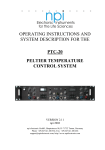
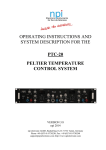
OPERATING INSTRUCTIONS AND
SYSTEM DESCRIPTION FOR THE
MTC-20/2S
TEMPERATURE CONTROL SYSTEM
VERSION 2.7
npi 2006
npi electronic GmbH, Hauptstrasse 96, D-71732 Tamm, Germany
Phone +49 (0)7141-9730230; Fax: +49 (0)7141-9730240
[email protected]; http://www.npielectronic.com
MTC-20/2S User Manual
_______________________________________________________________________________________________________________
Table of Contents
1. Safety Regulations .............................................................................................................. 3
2. MTC-20/2S Components.................................................................................................... 4
3. MTC-20/2S System ............................................................................................................ 4
3.1. System Description...................................................................................................... 4
3.2. Description of the Front Panel..................................................................................... 5
3.3. Rear Panel Elements.................................................................................................... 8
3.4. Electronic Control and Protection Circuits ................................................................. 9
3.5. Modes of Operation ..................................................................................................... 9
Modes of Operation Overview .................................................................................... 10
3.6. Setting the DESIRED TEMPERATURE .................................................................... 10
4. Grounding ........................................................................................................................... 11
5. Connection of the Sensor / DIN Connector ........................................................................ 11
6. Operating guide – Tuning procedure .................................................................................. 13
7. Literature............................................................................................................................. 16
8. Technical Data .................................................................................................................... 16
___________________________________________________________________________
version 2.7
page 2
MTC-20/2S User Manual
_______________________________________________________________________________________________________________
1. Safety Regulations
VERY IMPORTANT: Instruments and components supplied by npi electronic are NOT
intended for clinical use or medical purposes (e.g. for diagnosis or treatment of
humans), or for any other life-supporting system. npi electronic disclaims any
warranties for such purpose. Equipment supplied by npi electronic must be operated
only by selected, trained and adequately instructed personnel. For details please consult
the GENERAL TERMS OF DELIVERY AND CONDITIONS OF BUSINESS of npi
electronic, D-71732 Tamm, Germany.
1)
GENERAL: This system is designed for use in scientific laboratories and must be
operated by trained staff only. General safety regulations for operating electrical devices
should be followed.
2)
AC MAINS CONNECTION: While working with the npi systems, always adhere to the
appropriate safety measures for handling electronic devices. Before using any device
please read manuals and instructions carefully.
The device is to be operated only at 115/230 Volt 60/50 Hz AC. Please check for
appropriate line voltage before connecting any system to mains.
Always use a three-wire line cord and a mains power-plug with a protection contact
connected to ground (protective earth).
Before opening the cabinet, unplug the instrument.
Unplug the instrument when replacing the fuse or changing line voltage. Replace fuse
only with an appropriate specified type.
3)
STATIC ELECTRICITY: Electronic equipment is sensitive to static discharges. Some
devices such as sensor inputs are equipped with very sensitive FET amplifiers, which can
be damaged by electrostatic charge and must therefore be handled with care. Electrostatic
discharge can be avoided by touching a grounded metal surface when changing or
adjusting sensors. Always turn power off when adding or removing modules,
connecting or disconnecting sensors, headstages or other components from the
instrument or 19” cabinet.
4)
TEMPERATURE DRIFT / WARM-UP TIME: All analog electronic systems are
sensitive to temperature changes. Therefore, all electronic instruments containing analog
circuits should be used only in a warmed-up condition (i.e. after internal temperature has
reached steady-state values). In most cases a warm-up period of 20-30 minutes is
sufficient.
5)
HANDLING: Please protect the device from moisture, heat, radiation and corrosive
chemicals.
6)
INSTRUMENT COOLING: To prevent damage from overheated components, adequate
airflow around the heat sink in the rear of the instrument must be ensured.
___________________________________________________________________________
version 2.7
page 3
MTC-20/2S User Manual
_______________________________________________________________________________________________________________
2. MTC-20/2S Components
The following items are shipped with the MTC-20/2S system:
MTC-20/2S desktop cabinet
Power cord
User manual
Optional accessories:
Miniature temperature sensor
Subminiature temperature sensor
PT 100 temperature sensor
Recording chamber
ALA DIN connector cable assembly
Heated perfusion tube
Thermal foil
3. MTC-20/2S System
3.1.
System Description
The MTC-20/2S temperature control system is designed for heating purposes in
electrophysiological experiments. The MTC-20/2S system is housed in small desktop cabinet
that can be placed close to the microscope, with built-in power supply and cooling elements
for the power devices. The system guarantees low noise operation and has special protection
features to prevent the preparation from damage.
The MTC-20/2S incorporates two electronic thermometers for small semiconductor sensors
(R2252, i.e. the sensor has a resistance of 2252 Ω at 25 °C), two digital temperature displays
(XX.X °C), a set-point control with digital readout (XX.X °C), a PI (proportional-integral)
controller with adjustable parameters, an output power control unit and a high-power output
stage (DC, continuous operation) for resistive ( i.e. heat only) loads with electronic protection
circuits. The power output is short circuit protected, the output power is limited electronically.
Maximal output voltage is approximately 12 V, the current is limited to 1 A.
The system can be connected to the thermistors / heating elements in two ways:
Using separate cables for the sensors and the heating element or
Using the ALA DIN cable assembly that connects both, sensors and heating elements
A large variety of sensors and thermal elements are available (see also Optional accessories
in chapter 2). Please contact npi for details.
___________________________________________________________________________
version 2.7
page 4
MTC-20/2S User Manual
_______________________________________________________________________________________________________________
3.2.
Description of the Front Panel
Figure 1: MTC-20/2S front panel view
In the following description of the front panel elements each element has a number that is
related to that in Figure 1. The number is followed by the name (in uppercase letters) written
on the front panel and the type of the element (in lowercase letters). Then, a short description
of the element is given.
(1) DESIRED TEMP./°C potentiometer
Potentiometer to set the working temperature of the controller system. If the
display mode switch (11) is in position SETPOINT the preset value is
monitored on display A (2). Range: +25 °C….+50 °C.
(2) Display A
Digital display to indicate the DESIRED TEMPERATURE, the
temperature determined by SENSOR A or the voltage at the POWER
OUTPUT connectors (18/19). The function is selected by the display
mode switch (11).
___________________________________________________________________________
version 2.7
page 5
MTC-20/2S User Manual
_______________________________________________________________________________________________________________
(3) ALARM LED
This LED lights if temperature SENSOR A (13) is not connected, broken or shortcircuited. The POWER OUTPUT (18 / 19) shuts down if this LED is on and the
MODE switch (14) is set to SENSOR A.
(4) GAIN potentiometer
Potentiometer (logarithmic scale) to change the GAIN parameter (amplification of
the error signal, see chapter 3.4) of the temperature controller (PI controller),
range: 10 to ∞.
(5) INTEGRATION potentiometer
Potentiometer to set the INTEGRATION parameter (time constant) of the
temperature controller (PI controller), time range: 50 ms - 20 s.
(6) Display B
Digital display to indicate the temperature determined by sensor B
(16).
(7) ALARM LED
This LED lights if temperature SENSOR B (16) is not connected, broken or shortcircuited. The POWER OUTPUT (18 / 19) shuts down if this LED is on and the
MODE switch (14) is set to SENSOR B.
(8) LIMITER potentiometer
Potentiometer to set the voltage range of the POWER OUTPUT (18 / 19),
100% = 12 Volt.
(9) HEAT LED
This LED indicates the status of the POWER OUTPUT (18 / 19)
(LED on = heating).
___________________________________________________________________________
version 2.7
page 6
MTC-20/2S User Manual
_______________________________________________________________________________________________________________
(10) COMMAND INPUT 10mV/°C connector
BNC connector to set the working temperature of the controller system by an
external voltage signal. This input is scaled with the factor 10mV / °C.
(11) SENSOR A / SETPOINT / PWR OUT switch (display mode switch)
Switch to select the mode of display A (2):
SENSOR A (upper position):
SETPOINT (middle position):
PWR OUT ( (lower position):
the temperature determined by SENSOR A
(13) is displayed (XX.X °C)
the value preset at the DESIRED
TEMPERATURE
potentiometer (1) is displayed (XX.X °C)
the voltage at the POWER OUTPUT (18 /
19) is displayed.
(12) OUTPUT A 10mV/°C connector
BNC connector monitoring the temperature determined by SENSOR A (13),
sensitivity: 10mV / °C.
(13) SENSOR A connector
8-pole connector for temperature SENSOR A.
This connector also provides the POWER OUTPUT (18 / 19) for the heating unit
(max. 12V DC and 1A) for devices with the ALA DIN connector cable assembly.
(e.g. HPT-2A, see www.alascience.com).
(14) MODE switch
Switch to select the operation modes of the MTC-20/2S. Four modes
are available:
SENSOR A: the temperature determined by SENSOR A (13) is
used for the control system
DIRECT:
the voltage at the POWER OUTPUT (18 / 19) can be
set directly from the DESIRED TEMPERATURE
potentiometer (1) (0-12 V, no control)
EXT. SENSOR (EXTERN SENSOR): an external thermometer
connected to BNC (15) (sensitivity 1mV/°C) can be
used for the controller loop
SENSOR B: temperature determined by SENSOR B (16) is used as
feedback temperature in the controller loop.
___________________________________________________________________________
version 2.7
page 7
MTC-20/2S User Manual
_______________________________________________________________________________________________________________
(15) EXT. SENSOR 1mV/°C connector
BNC connector to connect external thermometer with a voltage output of 1mV/°C
(see (14)).
(16) SENSOR B connector
8-pole connector for temperature SENSOR B.
This connector also provides the POWER OUTPUT (18 / 19) for the heating unit
(max. 12V DC and 1A) for devices with the ALA DIN connector cable assembly.
(e.g. HPT-2A, see www.alascience.com).
(17) OUTPUT B 10mV/°C connector
BNC connector monitoring the temperature determined by SENSOR B (16),
sensitivity: 10mV / °C.
(18) / (19) POWER OUTPUT Max. 1A DC connectors
Banana jack connectors for the heating unit. This output supplies a
maximum voltage of 12V DC and a maximum current of 1 A.
POWER OUTPUT is also available at the SENSOR A (13) and SENSOR B
connectors (16) for devices with the ALA DIN cable assembly.
3.3.
Rear Panel Elements
POWER: The PWR switch turns on/off the power supply (115/ 230 V AC, max. 50 W). The
selector for the line voltage and the connector for the power cord are located on the rear panel
of the instrument.
FUSE: Line fuse: 0.8 A slow (115 V) or 0.4 A slow (230 V). It must be replaced only by
specified type. Please disconnect mains power plug when replacing fuse.
Caution: The instrument may be damaged if the wrong line fuse is installed e.g. 0.4 A if the
MTC-20/2S is operated at 115 V!
___________________________________________________________________________
version 2.7
page 8
MTC-20/2S User Manual
_______________________________________________________________________________________________________________
3.4.
Electronic Control and Protection Circuits
CONTROL LOOP
The sensor / thermometer, PI-controller, output power stage and heating element form a
closed loop control system. The desired temperature signal is compared with the output signal
obtained from the thermometer giving an error signal. This signal is amplified in the PI
controller and transferred to the output stage where it is converted to a high-power output
signal applied to the heating element (see also Figure 4).
ELECTRONIC PROTECTION CIRCUITS
Each system is equipped with two protection systems:
1. Sensor inputs: an electronic shut-off function disconnects the output if the sensor is
disconnected, broken or short-circuited.
2. Output protection: the output current and voltage are limited electronically.
Important: The sensor used for the control must be in good thermal connection with the
heating wire. If not overheating and damage may occur.
ALARM circuit
The internal thermometer (R2252 sensor) inputs are protected by the sensor alarm circuit (see
above). If this thermometer is used as input device for the PI controller, the ALARM circuit
disconnects the power output if the sensor is damaged or not connected. This state is indicated
by the red ALARM LED. If the DIRECT mode or EXT mode is used, the ALARM circuit is
disabled.
ACCURACY
Measuring accuracy of the internal thermometer is 0.1 °C, controller accuracy is 0.5 °C or
better (depending on the amount of heated solution).
3.5.
Modes of Operation
The system can be used in the following modes of operation:
DIRECT mode
DIRECT mode (no temperature control): the MODE switch (14, Figure 1) is set to the
DIRECT position. The control unit is not active, i.e. the output voltage is preset directly at the
DESIRED TEMP. control (1, Figure 1). With the setting from 25 to 50 the output voltage
increases linearly from 5 V to 12 V. The ALARM circuit (see below) is disabled in this mode.
The MTC-20/2S is designed with an unipolar output. If a resistive load is used, the system
can be used for heating purposes in all modes (SENSOR and DIRECT).
___________________________________________________________________________
version 2.7
page 9
MTC-20/2S User Manual
_______________________________________________________________________________________________________________
Internal SENSOR mode
In this mode the output voltage is controlled by the PI controller (PI [proportional-integral
controller system] activated). The temperature signal which is used for the control unit is
selected by the MODE switch.
The SENSOR A or SENSOR B position selects one of the internal thermometers
(SENSOR A or SENSOR B) which use a small semiconductor sensor. The measured
temperature is shown at the respective digital display unit (2 or 6, Figure 1
respectively, XX.X °C).
If no sensor is connected or if the sensor is damaged or short circuited the internal
shut-off unit disconnects the power output. This state is indicated by the red ALARM
LED (3 or 7, Figure 1 respectively) located just above the sensor connectors.
EXT. SENSOR mode
This mode can be used to connect an external thermometer. The calibration of the external
input (SENS. INPUT BNC, (15, Figure 1)) is 1 mV / °C. If this option is used the internal
ALARM circuit is disabled.
Modes of Operation Overview
DIRECT MODE:
output voltage is set directly by the DESIRED TEMP. °C control.
Internal SENSOR mode: output voltage is controlled by the PI controller using SENSOR A
or SENSOR B.
EXT. SENSOR mode:
output voltage is controlled by the PI controller using an external
thermometer.
POWER OUTPUT is always available at POWER OUTPUT, SENSOR A and SENSOR B.
3.6.
Setting the DESIRED TEMPERATURE
There are two ways to set the DESIRED TEMPERATURE:
1. The easiest way is to use the potentiometer DESIRED TEMP. / °C. The temperature
can be set with this potentiometer from +25.0 °C to +45.0 °C. If the MTC-20 leaves
this temperature window the internal shut-off unit disconnects the power output. This
could be the case if the sensor is broken or short-circuited.
2. If the user wants to have external control (e.g. with a computer system) or to set the
temperature to lower (<25 °C) values, the DESIRED TEMPERATURE can be set
using the COMMAND INPUT 10mV / °C connector (10, Figure 1). The COMMAND
INPUT is scaled 10mV / °C, i.e. +370 mV at this connector would set the DESIRED
TEMPERATURE to +37 °C.
Important: The set value of the temperature is always the sum of the setting at DESIRED
TEMP. / °C potentiometer and the voltage at COMMAND INPUT 10mV / °C connector, i.e.
if DESIRED TEMP. / °C is set to +25.0 °C and the voltage at COMMAND INPUT 10mV /
°C is +150 mV the temperature will be set to +40 °C !!
___________________________________________________________________________
version 2.7
page 10
MTC-20/2S User Manual
_______________________________________________________________________________________________________________
4. Grounding
To avoid ground loops, the internal ground of the system is floating, i.e. it is not connected to
the protective earth of the mains while the cabinet is always connected to protective earth
(green / yellow wire). The system can be grounded either via a BNC cable connected to
INPUT or OUTPUT (10 mV / °C) or via the blue OUTPUT (= GND) connector.
5. Connection of the Sensor / DIN Connector
Figure 2: How to connect the temperature sensor (non DIN cable)
Figure 3: Connector pinout of the DIN connector (pins 1 and 3 are connected internally)
___________________________________________________________________________
version 2.7
page 11
MTC-20/2S User Manual
_______________________________________________________________________________________________________________
Figure 4: Block diagram of the MTC-20/2S
___________________________________________________________________________
version 2.7
page 12
MTC-20/2S User Manual
_______________________________________________________________________________________________________________
6. Operating guide – Tuning procedure
After unpacking the instrument please check the appropriate voltage at the voltage selector at
the back panel. Also check that the sensor used for the control is in good thermal connection
with the heating wire.
Important: Make sure that the SENSOR or the external SENSOR, respectively, and the
heating device that is controlled by this SENSOR are using the same channel. Otherwise the
heating device may be damaged due to overheating.
In the following it is assumed that you use heating devices delivered by npi or ALA Scientific
Instruments. with 12V operating voltage. Please follow these instructions step by step to
avoid problems in adjusting the instrument.
•
Turn all potentiometers to the most left position
•
switch the MODE selector to the position SENSOR A or B depending on which sensor is
used as feedback temperature in the controller loop
•
set the DESIRED TEMPERATURE to e.g. 37 °C
DESIRED TEMP./°C
35 37 40
30
45
25
50
•
turn on the MTC-20/2S and wait at least 15 minutes to warm up the instrument. The
temperature display should show the actual temperature at the sensor
•
turn the LIMITER to 100%
LIMITER
50 %
0
100 %
Note: If you use heating wires with 6V operating voltage turn the LIMITER to 50% to
protect the wire from damage.
If the difference between the actual and the desired temperature is more than 10 °C the
HEAT-LED will light up slightly.
•
turn the GAIN to a position as shown below
GAIN
10
∞
___________________________________________________________________________
version 2.7
page 13
MTC-20/2S User Manual
_______________________________________________________________________________________________________________
The actual temperature at the sensor now approaches the desired temperature but will not
reach 37 °C because the control loop is not yet well adjusted. The actual temperature should
arrest at 1 to 2 °C below the desired temperature. Please wait until this steady state value is
reached. This may last several minutes. If this value is not reached set the GAIN to higher
levels until - in this example – 35 °C to 35.5 °C is reached. If you don’t get a steady state
value, set the LIMITER to 80-90% (or 30-40%, respectively) and wait again.
Now turn on the INTEGRATION and set it to a low level
INTEGRATION
OFF
MAX.
The actual temperature at the sensor will now reach the desired temperature possibly after a
small overshoot. Wait again until the steady state value is reached.
•
If the desired temperature is not reached first set the GAIN to a slightly higher level and
then – if necessary – raise the INTEGRATION
Note: The speed of the control circuit (and therefore the time in which the actual
temperature reaches the DESIRED TEMPERATURE) is highly dependent on the first
settings of GAIN and INTEGRATION. Thus, when beginning to use the MTC-20/2S we
recommend to try out several first settings of GAIN and INTEGRATION to find out which
settings are best for your experimental conditions.
If you use a perfusion system it is recommended to heat the solution approximately to the
desired temperature before perfusing the bath either with a heating foil wrapped around the
supplying tube (available from npi) or by heating up the supplying bowl.
As mentioned above it is very important that the sensor element and the heating element are
in good thermal connection.
___________________________________________________________________________
version 2.7
page 14
MTC-20/2S User Manual
_______________________________________________________________________________________________________________
In Figure 5 the time course of temperature regulation of the MTC-20/2S is shown. As
resistive load a bulb (12V, 21W) was used. The temperature sensor was fixed directly on the
bulb and sensor and bulb were wrapped with foam. Starting temperature was 27,3 °C. Starting
conditions were: LIMITER set to 0, GAIN set to 0, INTEGRATION off.
temperature (°C)
39
37
35
3
2
33
31
29
27
1
25
0
100
200
300
400
500
600
700
800
900
1000
time (s)
Figure 5: Time course of temperature regulation of the MTC-20/2S.
1: LIMITER was set to 100%, GAIN was set to a low level
2: GAIN was set to a slightly higher value (about 10% of the whole scale)
3: INTEGRATION was turned on at a low level
___________________________________________________________________________
version 2.7
page 15
MTC-20/2S User Manual
_______________________________________________________________________________________________________________
7. Literature
Kettenmann, H. and R.
Wiley-Liss, New York 1992
Grantyn
(eds.)
Practical
Electrophysiological
Methods,
Froehr, F. and F. Orttenburger Introduction to Electronic Control Engineering,
Siemens AG, Berlin and Munich 1982
8. Technical Data
Sensor input:
for semiconductor 2252 Ω at 25 °C (standard) or platinum
100 Ω at 0 °C, accuracy typically 0.1 °C at 25 °C, with
electronic protection
Sensor input (EXT. Mode):
sensitivity: 1 mV/°C
ALARM and SHUTOFF:
disconnects POWER OUTPUT if temperature is below +3 °C
(not connected or broken sensor) or above +45 °C (short
circuited sensor)
Digital displays:
3 1/2 digits, XX.X °C (temperature of SENSOR A or B) or
XX.X V (voltage at POWER OUTPUT)
COMMAND INPUT:
BNC connector, analog input, sensitivity. 10 mV/°C
Set value control:
potentiometer, range: up to 45.0 °C, XX.X °C or 0-100% of
output voltage (DIRECT mode)
Temperature OUTPUT (A, B): BNC connector, analog outputs, sensitivity. 10 mV/°C,
output impedance: 250 Ω
POWER OUTPUT:
12 V / 1 A, short circuit protected, continuous DC
Limiter:
potentiometer for the maximum output voltage with a linear
range from 0 – 100 %
Control:
PI (proportional-integral) controller, accuracy typically
±0.2 °C
GAIN:
potentiometer, logarithmic scale, range: 10-10k
INTEGRATION:
potentiometer, logarithmic scale, time range: 50 ms - 20 s
Measuring accuracy:
0.1 °C at 25 °C
Power requirements:
115 / 230V AC, 60 / 50 Hz, fuse 0.8 / 0.4 A slow
Dimensions:
desktop cabinet, 246 mm, 260 mm, 90 mm
___________________________________________________________________________
version 2.7
page 16