1
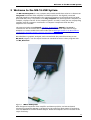
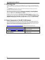
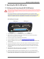
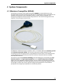
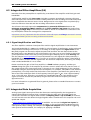
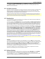
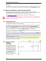
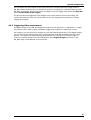
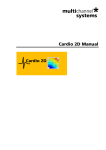
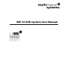
ME-16-USB System User Manual
Information in this document is subject to change without notice.
No part of this document may be reproduced or transmitted without the express written
permission of Multi Channel Systems MCS GmbH.
While every precaution has been taken in the preparation of this document, the publisher and the
author assume no responsibility for errors or omissions, or for damages resulting from the use of
information contained in this document or from the use of programs and source code that may
accompany it. In no event shall the publisher and the author be liable for any loss of profit or any
other commercial damage caused or alleged to have been caused directly or indirectly by this
document.
© 2006 Multi Channel Systems MCS GmbH. All rights reserved.
Printed: 2006-08-31
Multi Channel Systems
MCS GmbH
Aspenhaustraße 21
72770 Reutlingen
Germany
Fon
+49-71 21-90 92 5 - 0
Fax
+49-71 21-90 92 5 -11
[email protected]
www.multichannelsystems.com
Microsoft and Windows are registered trademarks of Microsoft Corporation. Products that are
referred to in this document may be either trademarks and/or registered trademarks of their
respective holders and should be noted as such. The publisher and the author make no claim to
these trademarks.
Table of Contents
1
Important Information and Instructions
4
1.1
Operator's Obligations
4
1.2
Guaranty and Liability
4
1.3
Important Safety Advice
5
2
Welcome to the ME-16-USB System
7
2.1
ME Product Line
8
2.2
Single Components of the ME-16-USB-System
8
3
Operating the ME-16-USB System
9
3.1
Setting up and Connecting the ME-16-USB System
9
3.2
Driver Installation
10
3.3
Software Installation
10
4
System Components
11
4.1
Miniature Preamplifier (MPA8I)
11
4.2
Integrated Filter Amplifiers (FA)
22
4.3
Integrated Data Acquisition
22
4.4
Digital Input/Output, System Synchronization
24
5
Troubleshooting
26
5.1
About Troubleshooting
26
5.2
No Computer Connection / No Recording Possible
26
5.3
Triggering / Digital Input Does not Work
27
6
Appendix
28
6.1
Pin Layout
28
6.2
Contact Information
30
6.3
Ordering Information
31
ME-16-USB System User Manual
1 Important Information and Instructions
1.1 Operator's Obligations
The operator is obliged to allow only persons to work on the device, who
•
are familiar with the safety at work and accident prevention regulations and have been instructed
how to use the device;
•
are professionally qualified or have specialist knowledge and training and have received
instruction in the use of the device;
•
have read and understood the chapter on safety and the warning instructions in this manual and
confirmed this with their signature.
It must be monitored at regular intervals that the operating personnel are working safely.
Personnel still undergoing training may only work on the device under the supervision of an
experienced person.
1.2 Guaranty and Liability
The General conditions of sale and delivery of Multi Channel Systems MCS GmbH always apply.
The operator will receive these no later than on conclusion of the contract.
Multi Channel Systems MCS GmbH makes no guaranty as to the accuracy of any and all tests and
data generated by the use of the device or the software. It is up to the user to use good
laboratory practice to establish the validity of his findings.
Guaranty and liability claims in the event of injury or material damage are excluded when they
are the result of one of the following.
•
Improper use of the device
•
Improper installation, commissioning, operation or maintenance of the device
•
Operating the device when the safety and protective devices are defective and/or inoperable
•
Non-observance of the instructions in the manual with regard to transport, storage, installation,
commissioning, operation or maintenance of the device
•
Unauthorized structural alterations to the device
•
Unauthorized modifications to the system settings
•
Inadequate monitoring of device components subject to wear
•
Improperly executed and unauthorized repairs
•
Unauthorized opening of the device or its components
•
Catastrophic events due to the effect of foreign bodies or acts of God
4
Important Information and Instructions
1.3 Important Safety Advice
Warning: ME/MEASystems include several instruments as individual components. Each
instrument is shipped with a separate user manual. The information in the individual user
manuals fully apply to the complete system. This manual is only to be understood as an
additional information. Read all user manuals thoroughly before setting up the system.
Warning: Obey always the rules of local regulations and laws. Only qualified personnel
should be allowed to perform laboratory work. Work according to good laboratory practice
to obtain best results and to minimize risks.
The product has been built to the state of the art and in accordance with recognized safety
engineering rules. The device may only
•
be used for its intended purpose;
•
be used when in a perfect condition.
•
Improper use could lead to serious, even fatal injuries to the user or third parties and damage to
the device itself or other material damage.
Warning: The devices and the software are not intended for medical uses and must not be
used on humans.
Malfunctions which could impair safety should be rectified immediately.
High Voltage
Electrical cords must be properly laid and installed. The length and quality of the cords must be in
accordance with local provisions.
Only qualified technicians may work on the electrical system. It is essential that the accident
prevention regulations and those of the employers' liability associations are observed.
•
Each time before starting up, make sure that the mains supply agrees with the specifications of
the products.
•
Check the power cords for damage each time the site is changed. Damaged power cords should
be replaced immediately and may never be reused.
•
Check the leads for damage. Damaged leads should be replaced immediately and may never be
reused.
•
Do not try to insert anything sharp or metallic into the vents or the case of the products.
•
Liquids may cause short circuits or other damage. Keep the devices and the power cords always
dry. Do not handle it with wet hands.
5
ME-16-USB System User Manual
Requirements for the installation
•
The equipment shall be correctly earthed or connected to ground.
•
The analog inputs should be closed or connected to active signals.
•
Connections to all inputs and outputs shall be made with screened cables specified by Multi
Channel Systems. The screen has to be connected to a solid earth or chassis connection. ESD
voltages at open lines may cause malfunction during operation.
•
The products shall only be operated from approved power packs (if necessary).
Requirements for the operation
•
Any physical damage of the MPA8I cable, such as a broken cable, causes a physical damage of the
miniature preamplifier that cannot be repaired.
•
Protect the MPA8I from heat. Do not autoclave!
•
You can clean the connectors of the MPA8I with distilled water in an ultra sonic bath, but keep
the cable away from the fluid. Dry the device with compressed air.
•
Use and keep the MPA8I always in a dry environment. Do not expose it to fluids or vapor for a
longer period of time.
6
Welcome to the ME-16-USB System
2 Welcome to the ME-16-USB System
The ME-16-USB System is a very compact and portable stand-alone solution. It features an
integrated 16-channel filter amplifier and data acquisition. The digitally converted
electrode signals are transmitted to the connected computer via universal serial bus (High
Speed USB 2.0). Thus, it is possible to use any computer as a data acquisition computer, for
example, a laptop. The size of the complete system is so small, it easily fits into a laptop bag
together with the computer. Interference of computer components with the data
acquisition are excluded.
The system includes two 8-channel miniature preamplifiers (MPA8I). The MPA8I is
connected to the microelectrodes for providing the initial tenfold amplification stage.
Adapters to contact standard microelectrodes such as Michigan probes from NeuroNexus
Technologies and the 8-Trode from ALA Scientific Instruments Inc. are available as
accessories.
Recorded data is graphed, analyzed, and reviewed with the powerful and easy-to-use
MC_Rack program. You can export the data in standard formats to other programs with
the MC_DataTool.
Figure 1 ME-16-USB System
With integrated 16-channel filter amplifier and data acquisition, and two 8-channel
miniature preamplifiers MPA8I. A 16-channel acute probe from NeuroNexus is hooked up
onto two MPA8Is via an MP-16-ADPT adapter. Probes and adapters are not included in the
scope of delivery.
7
ME-16-USB System User Manual
2.1 ME Product Line
The ME-16-USB System is the first of a new generation of universal recording systems that
do not need an external data acquisition card. Data transfer to any computer is realized via
USB.
The standard ME product line is based on a data acquisition card, the MC_Card, that is
installed in the data acquisition computer.
With the ME (multielectrode) and STG (stimulus generator) product lines, Multi Channel
Systems provides complete solutions for stimulation, recording, and data acquisition
from up to 128 channels, data analysis and export.
All ME products are intended for extracellular electrophysiological recordings in vivo,
and special in vitro applications. Typical applications include simultaneous spike and local
field potential recording; multi-unit and single-unit recording from awake behaving
animals, and multitrode (for example, Michigan probes, 8-Trode, or tetrode) recordings.
2.2 Single Components of the ME-16-USB-System
The following components are part of the ME-16-USB-System. Please make sure that you
have carefully studied the documentation on the single components before setting up your
system. All user manuals can be found on the installation volume shipped with the system.
Updated versions can also be downloaded from the MCS web site.
Web link to the user manuals download page on www.multichannelsystems.com
Product
User Manual / Reference
2 x 8-channel 10x miniature preamplifiers (MPA8I) ME-16-USB-System User Manual or
MPA8I User Manual
16-channel filter amplifier and data acquisition
ME-16-USB-System User Manual
Data acquisition and analysis software MC_Rack
and MC_DataTool
MC_Rack User Manual / Help and
MC_Rack Tutorial
8
Welcome to the ME-16-USB System
3 Operating the ME-16-USB System
3.1 Setting up and Connecting the ME-16-USB System
Warning: Please read the separate user manuals of all devices before installation, especially the
warnings and safety information. Make sure all devices are switched off before you connect them
to the power supply. Damage to the devices and even fatal injuries may result from improper
installation or use.
Note: Using a USB hub for connecting the ME-16-USB System to the computer is not
recommended. The system needs a broad bandwidth for the data transmission. Recording
might not be possible, especially if a second device that sends or receives continuous data
streams, for example a web cam or USB speakers, is connected to the same USB port.
1. Provide a power supply in the immediate vicinity of the installation site.
2. Place all devices on a stable and dry surface, where the air can circulate freely and the
devices are not exposed to direct sunlight.
3. Set up the computer (with installed MC_Rack program).
4. Set up the MPA8I as described in chapter Setting Up and Connecting the MPA.
5. Connect the MPA8Is to the main unit of the ME-16-USB System. Close all unused inputs with
terminal plugs.
6. Connect the USB output connector to a free USB 2.0 port of the data acquisition computer.
7. Connect the main unit to a power outlet of the same electrical system (connected to the
same ground/earth wire) as all other components of the setup, for example, the computer
or shielding.
8. Check the power LED on the front panel. It should light up as soon as the power line is
connected. If not, check the power source and cabling.
9. (Install the MC_Rack program from the installation volume if it is not already installed.)
10. Start the MC_Rack program and select the ME-16-USB System as the data source. Please see
the MC_Rack Help / User Manual for more details on how to define the data source.
9
ME-16-USB System User Manual
3.2 Driver Installation
The ME-16-USB System is a plug and play device. The driver is automatically installed
together with the MC_Rack program.
The Windows operating system detects a new hardware when the ME-16-USB System is
connected to the computer, if the program has not been installed beforehand. Simply
cancel the driver installation and proceed with the installation of the MC_Rack program.
Important: Please make sure that you have full control over your computer as an
administrator. Otherwise, it is possible that the installed hardware does not work
properly.
3.3 Software Installation
Please check the system requirements before you install the MC_Rack software. MCS cannot
guarantee that the software works properly if these requirements are not fulfilled. Please
see the MC_Rack Help or User Manual for more information. It is recommended that you
check the MCS web site for software updates on a regular basis.
Important: Please make sure that you have full control over your computer as an
administrator. Otherwise, it is possible that the installed software does not work properly.
11. Double-click Setup.exe on the installation volume.
The installation assistant will show up and guide you through the installation procedure.
12. Follow the instructions of the installation assistant.
The ME-16-USB System driver and MC_Rack are installed (or updated) automatically.
10
System Components
4 System Components
4.1 Miniature Preamplifier (MPA8I)
The 8-channel miniature head stage preamplifiers MPA8I is connected directly to the
microelectrodes in the test model to provide the first amplification stage of 10. Adaptors for
standard multielectrodes such as Michigan probes or the 8-Trode are available. The
miniature preamplifiers small size allows easy placement. The metal housing prevents the
amplifier from picking up external noise.
The MPA8I is a differential (type I) amplifier, that is, it includes additional common ground
and reference electrode inputs. The reference electrode is ideally identical to the
recording electrodes and placed into a comparable but inactive area or tissue. Background
or noise signals that are picked up by both the reference electrode and the recording
electrodes are removed.
The metal case provides electrical shielding. Electrode damage is prevented by the very
low bias current. The high input impedance ensures stable long-term recordings:
Ideally, the input impedance would be infinite. As low voltages are generally recorded, a
high current would flow if the input impedance were low. As a result, the amplifier would
not be able to deliver the current, and the voltage would break down. The miniature
preamplifier has a high input impedance to avoid this problem.
11
ME-16-USB System User Manual
4.1.1 Setting Up and Connecting the MPA
4.1.2 General Setup Recommendations
In the following, you find general recommendations for the installation. If you are using
Michigan probe or 8-Trode adapters available from MCS, please refer to the following
chapters for more information.
Important: It is important that the complete setup refers to a single common ground.
The reference input has always to be connected. It is recommended to use a reference
electrode. However, if you are not using a reference electrode, connect the reference input
to ground (GND). Otherwise, noise picked up by the reference input will be subtracted from
the recording signals. This will either lead to signal loss or to a very high noise level.
13. Ground the animal with a ground electrode of large surface area, for example, a liquid
gel adhesive electrode, that is connected to the ground of the setup, for example, a
large metal table or a Faraday cage, to avoid pickup of noise from the environment. The
ground electrode is best positioned in an electrically inactive region (not near muscle, nor
heart), for example, at the belly.
14. Connect the GND input or the metal case of the miniature preamplifier to the common
ground of the setup. (The GND input is internally connected to the metal case.)
15. Connect the reference electrode to the reference input of the miniature preamplifier.
Generally, a reference electrode is inserted into non-active tissue of the experimental
model. The reference electrode should be identical to the recording electrode so that both
electrodes see the same background noise. This is necessary because despite the grounding,
the animal’s body often has not exactly a potential of zero, due to the electrode impedance,
for example. The background noise is then subtracted from the recording signal, increasing
the signal to noise ratio. Please note that this may not work if the complete setup is not
properly grounded.
16. Connect the recording electrodes to the recording channels of the miniature
preamplifier. You can either use single electrodes or multitrodes with the miniature
preamplifier. MCS provides adapters for standard probes.
17. Connect all unused recording channels to the REF input or to the reference electrode
(or to the amplifier’s ground if that is not possible) to avoid noise pickup. As the total
amplifier gain generally lies in the range of 1000, even very small noise signals may
generate high noise signals.
12
Setting Up and Connecting the MPA
18. If you are not using a Faraday cage, it might be necessary to shield the complete setup with
aluminum foil or similar to prevent electrical interference from the outside. Connect the
aluminum foil to the ground of the setup (for example, the metal table).
Troubleshooting: If you observe problems with noise, check that the ground of the setup is
connected to exactly the same ground as the data acquisition computer. For example,
connect the metal table to the ground/earth wire of a free power outlet (of the same
electrical system), as the computer is generally connected to ground/earth via the power
plug, too. Also, connect the data acquisition computer’s metal case with a thick
ground wire to the ground of the setup (for example, the metal table), preferably with a
4 mm plug.
4.1.3 Testing the Noise Level of the Setup
A terminal plug that connects all inputs to ground,
and a model test probe that mimics the electrode
impedance are provided for testing the noise level of
the setup. Please note that all instruments were
thoroughly tested at the factory site before delivery. The
tests suggested below are mainly intended for
optimizing and troubleshooting your setup, to exclude
any damage that might have occurred during
transportation, or to fulfill your own guidelines, for
instance. It will take only a few minutes time and can
save you time and trouble in the long run. Multi Channel
Systems recommends running these tests before you
start your real experiments.
1. Shorten the inputs of one MPA8I with the terminal plug, and connect the model test probe
to the other MPA8I as shown in the picture (do not mismatch the polarity).
2. Connect the MPA8I with the test model probe to channels 1–8.
3. Connect the MPA8I with the terminal plug to channels 9–16.
4. Make sure that all other connections are appropriate, and that your setup has an
appropriate grounding and shielding as recommended in the chapter General Setup
Recommendations.
13
ME-16-USB System User Manual
Setting up MC_Rack
Please refer to the MC_Rack User Manual for more information.
1. Start MC_Rack.
2. Open the file MPA8I_NoiseTest.rck on the installation volume (see folder Tutorial). This
rack contains the virtual MC_Card instrument with a continuous raw data display and an
Analyzer to measure the peak-to-peak amplitude.
3. Click Start to start the recording.
— OR — Set up the rack on your own:
1. Click Set Channel Layout on the Edit menu. Select a 1-dimensional layout. Select the
number of electrode channels (at least 16).
2. Add the ME-16-USB to your virtual rack.
3. In the tree view pane of the virtual rack, select the ME-16-USB, and click the Hardware
tab. Enter the total amplifier gain according to the specifications of the instruments. For
example, for a miniature preamplifier with a gain of 10 and a following filter amplifier with
a gain of 100, the total gain is 1000.
4. Select an input voltage range of –819.2–818.8 mV and a sampling rate of 10000 Hz.
5. On the Edit menu, click Add Data Display to add a raw data display to your virtual rack.
5. In the virtual rack tree view pane, select the Display 1 and click the Layout tabbed page.
Set up a channel map with channels 1–16.
6. Adjust the display ranges to 500 ms and +/–50 µV.
7. On the Edit menu, click Add Analyzer to add an Analyzer to the virtual rack. Select all or
two typical channels on the Channels tabbed page. Select the Peak-Peak Amplitude
parameter on the Analyzer tabbed page.
8. On the Edit menu, click Add Parameter Display to add a Parameter Display to the
virtual rack.
9. In the virtual rack tree view, select the Display 2 and click the Layout tabbed page. Set up
a channel map with all channels that were assigned to the Analyzer.
10. Click the Ranges tabbed page and enter 0–10 s for the x range and 0–100 µV for the
y range.
14
Setting Up and Connecting the MPA
Typical Results
Typical results of this test are shown in the following screen shot.
Figure 2 Noise level test with MPA8I.
The noise level is 60 µV peak to peak with the provided test model probe (channels 1–8) and
20 µV peak to peak with grounded inputs (channels 9–16). The top window shows raw data;
the bottom window shows the extracted peak-to-peak amplitudes of channels 1 and 9. (The
miniature preamplifier was shielded by a metal case connected to the ground/earth of the
test lab.)
15
ME-16-USB System User Manual
4.1.4 Connecting Michigan Probes from NeuroNexus
→ Insert one pin array of the Michigan Probe adapter into one MPA8I, and the other into the
second MPA8I. Make sure that the orientation of the MPA8I is correct (see illustration).
Figure 3 Channel assignment, output pins.
Shown are the output pins of the adapter that are connected to the miniature preamplifiers
MPAI when looking directly at the pins. The numbered channels are the ground channels
(G), the reference channel (R), and the 8 recording channels (1-8) of the MPA8I.
16
Setting Up and Connecting the MPA
Figure 4
Channel assignment, input pins.
Shown are the input pins of the adapter that are connected to the probe. The
labelled channels are the ground channel (G), the reference channel (R), and the
8 recording channels (1-8) of the MPA8I. Please see the MPA8I User Manual for
details.
G and R have been connected together as factory-default settings. You can
change this connection to meet your requirements.
Important: Operation of the MPA8I is differential. The reference channel R has to
be used for obtaining a proper signal.
17
ME-16-USB System User Manual
4.1.5 Connecting 8-Trodes from ALA
The 8-Trode adapter (8-Trode-ADPT) allows a direct connection of the 8-Trode (from ALA
Scientific Instruments Inc., New York) for acute and chronic implantations to an 8-channel
miniature preamplifier (MPA8I).
Figure 5
8-Trode adapter pin assignment.
Shown are the input pins of the adapter that are connected to the probe, and the
output pins that are connected to the MPA8I. The labelled channels are the
ground channel (GND), the reference channel (R), and the 8 recording channels
(1-8) of the MPA8I.
→ Connect the 8-Trode adapter to the miniature preamplifier on one side and to the 8-Trode
on the other side, as shown in the photograph below.
The MPA8I has two ground inputs. The two ground outputs of the 8-Trode-adapter are
only required for connecting these two inputs to the ground of the adapter, they have no
additional function.
A 0 Ohm resistor is connected between the reference (R) input and output. This means,
the reference input is connected to ground, and all signals are measured against the
general ground of the setup. If the resistor is removed, the input is measured against the
input of the R pin, that is, the noise measured with the R electrode is subtracted from the
input signals of the 8 channels.
18
Setting Up and Connecting the MPA
4.1.6 Service and Maintenance
Cleaning the Connectors
Warning: It is recommended to avoid the use of cleaning solutions to avoid corrosion. If a
wet cleaning is required, use distilled water. Make sure that only the connectors touch the
liquid; do not submerge the miniature preamplifier or the cable. Otherwise, you can fatally
damage the electronics.
→ Clean the connectors with 70 % alcohol and cotton swabs from time to time.
→ If this does not provide satisfying results, insert only the connectors into a small beaker with
acetone or alcohol and sonicate for 10–20 s in an ultrasonic bath. Air-dry the miniature
preamplifier for about 5 min before use.
→ You can also clean the connectors with distilled water in an ultra sonic bath. Dry the
connectors with compressed air immediately after sonication and let the amplifier air dry
for at least 6 h before use.
Sterilization
Warning: Do not autoclave or sterilize miniature preamplifiers by high heat (above 70 °C)
or vapor. The resin is not heat-stable and may deform under heat. Vapor can lead to a
corrosion of the electronics.
Miniature preamplifiers can be sterilized with standard methods that are not based on high
heat or vapor, for example, with 70 % ethanol, UV-light, or by thermal sterilization in an
oven at 56 °C with an incubation time of 8 hours.
19
ME-16-USB System User Manual
4.1.7 MPA8I Pin Layout
Power Supply
Supply voltage is applied to the output connector pins 8 and 15. The voltage source should
supply a stable noise-free voltage. Do not exceed the maximum voltage.
Pin 8: –3 V to –8 V
Pin 15: +3 V to +8 V
Warning: Do not mismatch the polarity of the power supply. A false connection may damage
the unit.
Input Connector
Please note that the black side is considered the top side.
1
Ground (GND)
2
Reference input
3 ... 10
Recording channels 1 to 8
11
Ground (GND)
Output Connector (Male)
1
3
2
9
10
4
11
5
12
6
13
7
14
8
15
1
Ground (GND)
9
Signal ground*
2, 10, 3, 11, 4, 12, 5, 13
Recording channels 1-8
6, 14, 7
Ground (GND)
15
Positive supply voltage
8
Negative supply voltage
* = Connected to the ground of the amplifier. The signal ground is used as the reference for
the following filter amplifier.
20
MPA8I Pin Layout
Test Model Probe
Test signal IN: You can use the jumper to connect the signal input pin (Signal IN) to
ground (standard situation for a noise level test), or you can connect a data source, for
example, a sine wave generator to the input (and the ground of the test signal to the signal
ground input) to test the signal distribution. The input signal is distributed across all
recording channels.
REF IN: The standard situation in an experiment should be that the reference electrode has
properties identical or close to the recording electrodes. You can remove the jumper to
connect the reference output of the test model probe to the same resistors as the recording
channels to mimic the experimental situation, or you can use the jumper to connect the
reference output to ground.
DC resistance
Dynamic resistance
Capacitance
4.7 MOhm
330 kohm
150 pF
21
ME-16-USB System User Manual
4.2 Integrated Filter Amplifiers (FA)
Raw data from the preamplifiers is amplified by a 16-channel filter amplifier with fixed gain and
bandwidth.
A differential amplifier with input type I includes a common ground and a common reference
electrode input. The reference electrode is ideally identical to the recording electrodes and placed
into a comparable but inactive area or tissue. Background or noise signals that are picked up by
both the reference electrode and the recording electrodes are removed.
The reference electrode input also compensates the potential difference between the
miniature preamplifier (MPA) output and the filter amplifier (FA) input that results from
the supply voltage drop in the line from the MPA to the FA. If two MPAs are connected to the
FA, the amplifier offsets are averaged for compensation.
Important: It is very important that the reference electrode inputs are always connected. Connect
it to ground when you are not using a reference electrode.
4.2.1 Signal Amplification and Filters
The filter amplifier combines a band pass filter and the signal amplification in one instrument.
The broad bandwidth of 1–5000 Hz is suitable for a broad range of applications, such as spike and
field potential recording from neurons or recording of cardiac signals. The digital filter of the
MC_Rack program can be used to adjust the pass band and filter the raw data. Please see the
MC_Rack Help or User Manual for more information. This way, you are very flexible in designing
your experiments. Please note that you may need a higher sampling rate to avoid aliasing. See
also the chapter Data Acquisition for more information. For slow signals like field potentials, a
bandwidth of 1–300 Hz is appropriate. If you like to record fast signals like spikes, a pass band of
300 Hz to 3 kHz is suitable. Cardiac signals have fast and slow components; therefore, you usually
need a wider bandwidth of 1 Hz to 3 kHz.
Please note that the gain of the filter amplifier is a fixed hardware property; and that you
cannot change the gain of the amplifier by software controls. Please also note that the ratio of
the output signal to the input signal, that is, the gain, is not a fixed parameter for the complete
bandwidth. The gain that was specified for the amplifier, for example, 100 (1000 in total with the
preamplifier), is not fully reached at the borders of the amplifier's pass band. The general rule is,
that at the lower and upper limit of the frequency band, the gain is 2 / 2 , that is approximately
70 %, of the full gain. Therefore, you should use a bandwidth that is at a safe distance of the
signals of interest. Outside the pass band, the gain decreases with the frequency and finally
approaches zero.
For more information on gain and filters in general, please refer to standard literature or contact
your local retailer.
4.3 Integrated Data Acquisition
Analog input signals are acquired from the data source and digitized by the integrated 16channel analog-digital converter that is integrated into the main unit. Recorded signals are
converted in real time into digital data streams at sampling rates of up to 50 kHz per channel.
You will not miss even the fastest biological signals. Data is transferred to the computer via a Full
Speed USB 2.0 port.
A 16-bit digital (TTL) input/output channel is available. You can use the digital TTL inputs for
example for synchronizing stimulation and recording, or for synchronizing the ME System with
other systems, video tracking, for example. The digital TTL outputs can be used for triggering
other systems and instruments, for example, for applying a feedback.
22
System Components
You configure the input voltage range from +/- 400 mV to +/- 4V and the sampling rate with
the software controls in the MC_Rack program. Please refer to the MC_Rack Help or User
Manual for more information.
4.3.1 DC Offset Correction
An offset correction is generally not necessary, because the intrinsic DC offsets of the ME-16-USB
System is very low in comparison to the signals of interest. You can use the MC_Rack offset
correction feature to remove even this low offset and reset all channels to zero. Please refer to
the MC_Rack Help or User Manual for more information.
Note: If you observe a large offset on any channel(s), you should contact your local retailer for
troubleshooting. The offset correction is not intended for removing large offsets, because the
offset correction will decrease the input voltage range.
4.3.2 Sampling Rate
It is recommended to adjust the sampling rate according to your signals, because the higher the
sampling rate, the bigger the file size will be.
As a rule of thumb, the sampling rate should equal five times the highest signal frequency
for a good digitized representation of the continuous analog signals. If the sampling rate is too
low, you will miss signals and/or see artifacts. For example, this means approximately 15 kHz for
spike recording, or 10 kHz for cardiac signals (which have fast and slow waveform components).
Please note that the sampling rate also depends on the amplifier’s bandwidth. According to the
Nyquist-Shannon sampling theorem, the sampling rate should be at least twice the bandwidth
of the analog (hardware) low pass filter, that is 10 kHz sampling rate when using a filter
amplifier with a cutoff frequency of 5 kHz. The 1/2 bandwidth frequency is also called Nyquist
frequency. You should not lower the sampling rate when using a low-pass digital filter. This is
the case because the whole amplifier bandwidth is recorded and then high frequency noise is
removed with the digital low pass filter after recording. Frequencies (noise) that are above half
the sampling rate (for example above 2.5 kHz at a 5 kHz sampling rate) will be transformed into
lower frequencies. This is called aliasing. The resulting low-frequency noise passes the digital low
pass filter and increases your noise level. You may ignore these recommendations if saving hard
disk space is more important for your application than the noise level.
Note: The sampling frequency should be at least five times the highest signal frequency and at
least twice the bandwidth of the filter amplifier.
Example:
You have a broadband filter amplifier with a bandwidth of 1 Hz to 5 kHz. The expected signals
have a maximum frequency of 1 kHz. Therefore, you want to filter the data with a digital low pass
filter and a cutoff frequency of 1 kHz. A sampling rate of 5 kHz (five times the highest signal
frequency) would be required for faithfully reproducing the signals, but you should use a
sampling rate of at least 10 kHz because the sampling rate should equal twice the bandwidth of
the analog filter, regardless of the digital filter properties.
If you had an amplifier with a cutoff frequency of 1 kHz instead, no digital filter would be
required, and a sampling rate of 5 kHz would be sufficient.
4.3.3 Software Package
With the high-performance data acquisition and analysis program MC_Rack, you can flexibly
manage all data streams. For example, you can display the raw data of all channels while
recording only the raw data of the channels of interest and the extracted parameters of all
channels. This saves computer performance and hard disk space.
23
ME-16-USB System User Manual
MC_Rack is not limited to special applications, but can be flexibly adapted to a wide range of
applications.
The mcd data format is support by several third party programs for further analysis. You can also
easily convert recorded data to universal formats such as ASCII with the MC_DataTool program.
4.4 Digital Input/Output, System Synchronization
TTL stands for Transistor-Transistor Logic. A TTL pulse is defined as a digital signal for
communication between two devices. A voltage between 0 V and 0.8 V is considered as a logical
state of 0 (LOW), and a voltage between 2 V and 5 V means a 1 (HIGH).
See Digital IN/OUT Connector in the Appendix for information on the pin layout.
Warning: A voltage that is higher than +5 Volts or lower than 0 Volts, that is, a negative voltage,
applied to the digital input would destroy the electronics. Make sure that you apply only TTL
pulses (0–5 V) to the digital inputs.
4.4.1 Triggering MC_Rack
The digital input accepts TTL pulses. This feature can be used for triggering MC_Rack, for example
for synchronizing stimulation and data acquisition.
For example, you can connect the Sync Out of an STG (stimulus generator) to one of the digital
input bits. If you use only one instrument for triggering, connect it to bit 0, for example. In
MC_Rack, add a Trigger Detector to your virtual rack, and select the Digital Data D1 input
stream as the Trigger. Select the appropriate logical state (generally HIGH) for triggering. Mask
all unused bits. The standard settings of the Trigger Detector are for using bit 0.
Please see the documentation on the Trigger Detector instrument and on triggered data in the
MC_Rack Help or User Manual for more details.
Important: It is recommended to set the duration of a TTL pulse according to the sampling rate.
The TTL pulse must be long enough to cover at least one data point. For example, if you have a
sampling rate of 10 kHz, a data point is recorded each 100 µs. Therefore, TTL input pulses must be
at least 100 µs long to make sure that it is detected by the system. MC_Rack will miss some or all
pulses if the pulse duration is shorter.
Please mask unused (not connected) digital input channels in the MC_Rack program to ignore
undefined states of the open inputs that can cause unwanted trigger events. Please see the
MC_Rack User Manual for more details.
4.4.2 Custom Switch for
"RemoteControlling"
You can connect any device
that produces TTL outputs,
for example a switch, to one
of the digital input bits. This
means you can use a trigger
for remote controlling the
recording with MC_Rack, or
for synchronizing systems, if
the data acquisition
computer is not within reach
during an experiment.
24
System Components
You can define the time length of the cutouts that are recorded around the trigger event in
MC_Rack. Please note that it is not possible to start the recording of a continuous data file with
MC_Rack on a trigger, but you can start a new data file on the trigger event (select the Recorder
option Create New File On Trigger).
The picture shows a suggested circuit diagram for a switch used for remote controlling. The
resistor and capacitor work as a low-pass filter on the TTL signal and are necessary to reduce
ringing of the signal.
4.4.3 Triggering Other Instruments
The digital output of the ME-16-USB System sends 20 ms TTL pulses (0 V = LOW and 5 V = HIGH).
This feature can be used to apply a feedback triggered by a signal or a parameter stream.
For example, you can connect the Trigger In of an STG (stimulus generator) to the digital output.
You can also use the digital output for a synchronization of the ME-16-USB System with other
systems, for example, for video tracking (provided that the other system of choice is able to
receive TTL pulses). Please see the documentation on the Digital Output instrument in the
MC_Rack Help or User Manual for more details.
25
ME-16-USB System
5 Troubleshooting
5.1 About Troubleshooting
The following hints are provided to solve special problems that have been reported by users. Most
problems occur seldom and only under specific circumstances. Please check the mentioned possible
causes carefully when you have any trouble with the product. In most cases, it is only a minor
problem that can be easily avoided or solved.
If the problem persists, please contact your local retailer. The highly qualified staff will be glad to
help you. Please inform your local retailer as well, if other problems that are not mentioned in this
documentation occur, even if you have solved the problem on your own. This helps other users,
and it helps MCS to optimize the instrument and the documentation.
Please pay attention to the safety and service information in the separate user manuals of the
related products and in the software help. Multi Channel Systems has put all effort into making
the product fully stable and reliable, but like all high-performance products, it has to be handled
with care.
5.2 No Computer Connection / No Recording Possible
You cannot establish a connection to the computer. The ME-16-USB channel layout is not available
in MC_Rack. When loading a previously saved virtual rack file, you will get an error message and
the simulator will be started automatically.
Or you get an error message when starting the recording in MC_Rack after a successful computer
connection.
Possible causes:
?
The power LED is not lighting. The supply power is not connected or there is a technical problem
with the instrument.
→ Check the power source and the cable connections. If this does not solve the problem, contact
your local retailer for support.
?
The power LED is lighting. The USB port might not support USB 2.0 or might not be working.
→ Check the USB port. Only full speed USB 2.0 ports can be used. Try another USB 2.0 port.
?
You can establish a connection, but get an error message when starting the recording in
MC_Rack. The bandwidth of the USB port is not sufficient for recording. This can be the case if the
ME-16-USB System is connected via a USB hub, and a second device that sends or receives
continuous data streams, for example a web cam or USB speakers, is connected to the same USB
port.
→ Connect the ME-16-USB System directly to a USB port, not via a hub.
26
Troubleshooting
5.3 Triggering / Digital Input Does not Work
You have connected a TTL source (for example, the Sync Out of a stimulus generator) to the
digital input of the ME-16-USB System, and configured the virtual rack in MC_Rack for triggering
displays or data acquisition by the TTL source, but you do not see any sweeps.
Possible causes:
?
The TTL source does not generate true TTL signals (5 V), or the TTL pulse duration is too short in
combination with the sampling rate, so that the pulse is missed in-between two data points.
→ The ME-16-USB System can only accept TTL signals (CMOS 5 V TTL level) as a digital input stream.
The TTL pulse needs to be optimized according to the sampling rate. Otherwise, a detection of the
trigger cannot be guaranteed.
?
The software settings for the Trigger Detector do not match with the hardware configuration.
→ In MC_Rack, add a Trigger Detector to your virtual rack, and select the Digital Data D1 input
stream as the Trigger. Check the pin layout of the digital IN/OUT connector and make sure that
the same bit input that is connected is selected in the software. (The standard settings of the
Trigger Detector are for using bit 0.) Mask all unused bits. Select the appropriate logical state
(generally HIGH) for triggering. Please see the MC_Rack Help or User Manual for more details.
27
ME-16-USB System
6 Appendix
6.1 Pin Layout
6.1.1 MPA8I Inputs
28
Appendix
6.1.2 Digital IN/OUT Connector
29
ME-16-USB System
6.2 Contact Information
Local retailer
Please see the list of official MCS distributors on the MCS web site.
User forum
The Multi Channel Systems User Forum provides an excellent opportunity for you to exchange
your experience or thoughts with other users worldwide.
Web link to the User Forum
Mailing list
If you have subscribed to the ME-System Mailing List, you will be automatically informed about
new software releases, upcoming events, and other news on the product line. You can subscribe
to the list on the MCS web site.
www.multichannelsystems.com
30
Ordering Information
6.3 Ordering Information
Please contact your local retailer for pricing and ordering information.
6.3.1 ME-USB Systems
Product
Product Number
Description
ME recording system
with 16 analog channels and
filter amplifier with fixed gain
ME-16-USB-System
Stand-alone system for extracellular
recordings, complete with 2 x MPA8I,
integrated FA16I, integrated 16-ch.
data acquisition, USB 2.0 data transfer
to computer, and software package
Product
Product Number
Description
Data acquisition system
with 16 analog channels
ME16 System
Data acquisition system
with 32 analog channels
ME32 System
Complete with data acquisition
computer with MC_Card and IPS10W,
and software package
Data acquisition system
with 64 analog channels
ME64 System
Data acquisition system
with 128 analog channels
ME128 System
ME recording system
with 16 analog channels and
filter amplifier with fixed gain
ME16-FA-System
Complete with 2 x MPA8I, SC8x8, FA16I,
data acquisition computer with
MC_Card and IPS10W, and software
package
ME recording system
with 32 analog channels and
filter amplifier with fixed gain
ME32-FA-System
Complete with 2 x MPA32I, SC2x32,
FA32I, data acquisition computer with
MC_Card and IPS10W, and software
package
ME recording system
with 64 analog channels and
filter amplifier with fixed gain
ME64-FA-System
Complete with 2 x MPA32I, SC2x32,
FA64I, data acquisition computer with
MC_Card and IPS10W, and software
package
ME recording system
with 128 analog channels and
filter amplifier with fixed gain
ME128-FA-System
Complete with 4 x MPA32I, 2 x SC2x32,
2 x FA64I, data acquisition computer
with MC_Card and IPS10W, and
software package
ME recording system
with 16 analog channels and
filter amplifier with
programmable gain
ME16-PGA-System
Complete with 2 x MPA8I, SC8x8,
PGA16, data acquisition computer with
MC_Card and IPS10W, and software
package
ME recording system
with 32 analog channels and
filter amplifier with
programmable gain
ME32-PGA-System
Complete with 2 x MPA32I, SC2x32,
PGA32, data acquisition computer with
MC_Card and IPS10W, and software
package
6.3.2 Standard ME Systems
31
ME-16-USB System
ME recording system
with 64 analog channels and
filter amplifier with
programmable gain
ME64-PGA-System
Complete with 2 x MPA32I, SC2x32,
PGA64, data acquisition computer with
MC_Card and IPS10W, and software
package
ME recording system
with 128 analog channels and
filter amplifier with
programmable gain
ME128-PGA-System
Complete with 4 x MPA32I, 2 x SC2x32,
2 x PGA64, data acquisition computer
with MC_Card and IPS10W, and
software package
6.3.3 Amplifiers
Product
Product Number
Description
Miniature preamplifier with 2
electrode inputs
MPA2I
Miniature preamplifier with 8
electrode inputs
MPA8I
Small sized and light weight
headstage with common ground and
additional indifferent reference
electrode input, input type I, gain = 10
6.3.4 Accessories
Product
Product Number
Description
16-ch. Michigan Probe adapter
MP-16-ADPT
Allows a direct connection of a 16channel Michigan probe to two
miniature preamplifiers MPA8I.
8-Trode adapter
8-Trode adapter
Allows a direct connection of the 8Trode from ALA Scientic Instruments
Inc. to the MPA8I.
Product
Product Number
Description
1-Channel stimulus generator
STG1001
2-Channel stimulus generator
STG1002
4-Channel stimulus generator
STG1004
8-Channel stimulus generator
STG1008
General purpose stimulators for a very
wide variety of applications. Flexible
and easy-to-use MC_Stimulus software
enables complex stimulus waveforms
(both current and voltage).
Stimulus isolation units are integrated
in the STG for each channel.
With additional digital trigger in- and
output.
4-Channel stimulus generator
STG2004
8-Channel stimulus generator
STG2008
6.3.5 Add-ons for stimulation
32
Advanced version with 4 additional
digital trigger in- and outputs. About
100 x faster download via USB. 16
times more memory for long-time
stimulation.
Ordering Information
6.3.6 Multielectrode Arrays
Multielectrode arrays are not available from Multi Channel Systems, but from several other
providers. The following are compatible with the miniature preamplifiers from Multi Channel
Systems. If you are interested in a particular probe that is not mentioned here, please ask Multi
Channel Systems or your local retailer for compatibility.
Product
Description
Supplier
Michigan probes
16-channel silicon probes
NeuroNexus Technologies
www.neuronexustech.com
8-Trode
Electrodes with eight pads, for in vivo acute
or chronic implantation
ALA Scientific Instruments, Inc.
www.alascience.com
33
Technical Specifications
Date of Print: 22.08.2006
ME-16-USB System
Operating temperature
Storage temperature
Relative humidity
10 °C to 50 °C
0 °C to 50 °C
10 % to 85 %, non-condensing
2 x 8-Channel Miniature Preamplifier (MPA8I):
Dimensions (W x D x H)
Weight
Maximum tensile strength of cable
Input connector type
Number of input channels
Input voltage
Input impedance
Input noise
Noise density
17 mm x 25 mm x 1.8 mm
1.3 g w/o cable and plug, 21 g with cable and plug
2 kg
Single-row precision sockets, 50 mil (1.27 mm) grid pattern, for 0.35-0.45 mm round pins)
8
± 500 mV (with respect to a supply voltage of 5 V)
1012 Ω parallel to 10 pF
< 1.5 µV RMS (1 Hz to 5 kHz, inputs short-circuited)
en = 15 nV / Hz
Bandwidth
Gain
DC to 50 kHz
10
16-Channel filter amplifier:
Number of input channels
Input voltage
Input impedance
Input noise
16
AC Coupled
2.2 MΩ
< 1 µV RMS (full bandwidth, inputs short-circuited)
Noise density @ 1 kHz
en = 9 nV / Hz
Bandwidth
1-5000 Hz *
Filter slope
80 db/decade
Gain
100 *
* Other gain and filter settings available on request.
16-Channel data acquisition:
Sampling frequency
Data resolution
Crosstalk (channel to channel)
Up to 50 kHz (software controlled)
16 bit
typically 0.01 %
Number of analog input channels
16
Number of digital input channels
Input signals
16
TTL (CMOS 5 V TTL level)
Number of digital output channels 16
TTL (CMOS 5 V output)
Output signals
Interface and connectors:
Analog inputs
16 Digital input and output bits
Data transfer
2 x 15 Pin SubD for MPA8I
37-Pin Sub D connector
USB 2.0 High Speed (true USB 2.0 transfer rate)
External power supply:
Input voltage range
Supply voltage
Supply current
110-240 V
9 V DC
200 mA
MC_Rack program:
Data Acquisition and analysis software
Operating system
Windows 2000, or XP with NTFS; English and German versions supported
Export features via MC_DataTool:
Data Export
Page 1 of 1
Axon Binary File (*.abf), ASCII file (*.txt), and binary file (*.raw) format
© 2006 Multi Channel Systems MCS GmbH