1
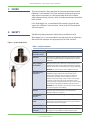
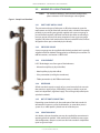
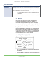
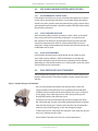
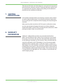
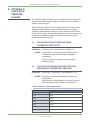
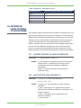
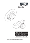
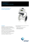
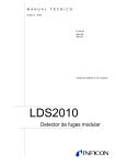
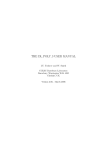
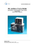
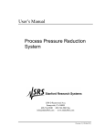
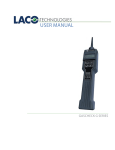
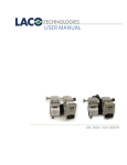
USER MANUAL
CALMASTER™ LEAK STANDARDS
CONTACT US
PHONE/FAX
Toll Free: 800.465.1004
Phone: 801.486.1004
Fax: 801.486.1007
ADDRESS
LACO Technologies, Inc.
3085 West Directors Row
Salt Lake City, UT 84104
WEB
www.lacotech.com
[email protected]
SMT-07-1014 rev A2
ii
© 2010 LACO TECHNOLOGIES, INC.
CONTENTS
1.
SCOPE ................................................................................... 1
2.
SAFETY ................................................................................. 1
3.
OVERVIEW............................................................................ 2
4.
BASIC OPERATION ............................................................. 4
5.
MAINTENANCE ................................................................. 10
6.
CALIBRATION OF LEAKS ................................................. 10
7.
SHIPPING INSTRUCTIONS .............................................. 11
8.
WARRANTY INFORMATION............................................ 11
9.
APPENDIX A: LEAKS WITH PRESSURE GAUGES......... 12
10. APPENDIX B: LEAKS FLOWING TO ATMOSPHERE ..... 13
iii
© 2010 LACO TECHNOLOGIES, INC.
LACO USER MANUAL - CALMASTER™ LEAK STANDARDS
1. SCOPE
This manual contains safety, operation, and maintenance information for
CalMaster™ Leak Standards. LACO leak standards are designed to ensure
safety when used properly. It is the responsibility of the user to follow
safety-related warnings, cautions, notes, and other requirements described
in this manual.
LACO Technologies, Inc. is committed to full customer support of every
aspect of its CalMaster™ Leak Standards. Call or email LACO for technical
sales and support.
2. SAFETY
The following safety precautions should always be followed. LACO
Technologies, Inc., is not responsible for damage to persons or equipment
that results from improper or inappropriate use of a leak standard.
Figure 1: Leak Standard Seal
Table 1: Safety Precautions
COMPONENT
PRECAUTION
TAMPERRESISTANT SEALS
Do not open or break tamper-resistant seals.
VENTING
When venting a refillable reservoir, point valve away from
face, body, and other people. For refill instructions, see 4.2
REFILLING.
PRESSURIZING
RESERVOIRS
DOT-approved reservoirs (which are clearly marked on the
outside of the bottle) can be safely pressurized to 1800 psig,
while all others have a maximum pressure rating of 400 psig.
WARNING Do not over-pressurize a refillable reservoir.
Special precaution should be taken regarding certain
LACO Technologies custom fill valves having metal/
solder tamper-resistant seals (see Figure 1). Under no
circumstances should this seal be broken, loosened,
melted, or removed. Doing so may result in serious injury
to persons or damage to property. Should this seal be
compromised by accidental or other means, contact LACO
Technologies immediately for further safety precautions.
MAINTAIN SEAL
INTEGRITY
WARNING Do not attempt to re-pressurize a reservoir that
was not designed for user-refilling.
GASSES
Do not use gas other than what is specified on the
calibration label and certificate.
HAZARDOUS
GASSES
Do not use toxic or hazardous gases with any leak standard.
LEAK STANDARD
CARE
Do not drop, throw, puncture, incinerate, or otherwise
compromise a pressurized reservoir. Do not re-pressurize a
reservoir that has been damaged.
TEMPERATURE
Do not heat reservoir above 50°C; do not cool below 0°C.
LEAK STANDARD
DAMAGE
If physical signs of damage to a leak standard are evident,
discontinue use and return it to the factory for repair.
1
© 2010 LACO TECHNOLOGIES, INC.
LACO USER MANUAL - CALMASTER™ LEAK STANDARDS
3. OVERVIEW
A leak standard is a device that, under prescribed conditions, emits a
controlled flow of a specified gas. This device consists of a leak element
(either a physical orifice or a gas-permeable membrane) that allows gas
to pass through to the outlet of the device at a controlled rate. That rate,
called the leak rate can be accurately quantified by means of calibration.
3.1
SPECIFICATIONS
Table 2: Leak Specifications
TEFLON
GLASS
CRIMPED
CAPILLARY
MICRO-TUBE
CAPILLARY
GAS
Helium
Helium
Helium/Other
gases*
Helium/Other
gases*
LEAK RATE
RANGE
10-8 to 10-3
atmcc/sec
10-10 to 10-7
atmcc/sec
10-7 to 10
atmcc/sec
10-9 to 1
atmcc/sec
0.1%/°C
(Reservoir-style)
TEMPERATURE
COEFFICIENT
2.0 % / ºC
DEPLETION
RATE
Target value: <3%/year; actual depletion rate is dependant on
pressure, reservoir size and leak rate.
CALIBRATION
UNCERTAINTY
Refer to section 3.1.10 Uncertainty
4.0 % / ºC
0.2 % / ºC
-0.5%/°C
(Open-style)
*Non-hazardous, non-radioactive
Most of LACO CalMaster™ leak standards now feature our proprietary
micro tube capillary leak elements. Our micro tube capillary has
undergone a rigorous validation process to verify the reliability of the leak
standard.
Table 3: Leak Element Comparison
LEAK
ELEMENT
GASES
LEAK
RATE
TEMP
COEF.
CLOGGING
VACUUM
RESPONSE
STABILITY DURABILITY
PRESSURE
RESPONSE
Glass
Helium Only 10-7 - 10-10
Permeation
4% per °C None
Fair
Excellent
Breakable
Fair
Teflon
Helium Only 10-4 - 10-8
Permeation
2% per °C None
Fair
Fair
Unbreakable
Fair
Metal
Capillary
All Gases
10-1 - 10-6
0.2% per
°C
Frequent
Excellent
Varies
Unbreakable
Excellent
Micro Tube
Capillary
All Gases
10-1 - 10-10
0.1 % per
°C
Very Rare
Excellent
Excellent
Unbreakable
Excellent
2
© 2010 LACO TECHNOLOGIES, INC.
LACO USER MANUAL - CALMASTER™ LEAK STANDARDS
3.2
MAKEUP OF A LEAK STANDARD
NOTE
For available CalMaster™ leak standard configurations,
please contact a LACO Technologies sales engineer.
Figure 2: Sample Leak Standard
3.2.1
INLET PORT OR FILL VALVE
The presence and types of inlet ports or fill valves depends upon the
requirements and style of the leak standard. Leaks standards that require
periodic re-pressurizing are typically supplied with a pressure gauge as
part of the leak standard, while leak standards that have an external gas
pressure source will not (with some exceptions) have a pressure gauge
supplied. Still, other leak standards have factory-sealed fill valves and are
designed to be re-pressurized only by the factory.
3.2.2
PRESSURE GAUGE
A pressure gauge may be supplied with the leak standard and is typically
supplied with leak standards designed to be re-filled by the customer. For
refill instructions, see Section 4.2 REFILLING.
3.2.3
LEAK ELEMENT
LACO Technologies uses four types of leak elements:
• Micro-tube capillary (a physical orifice)
• Metal capillary (a physical orifice)
• Glass permeation (a solid glass membrane)
• Teflon permeation (a solid Teflon membrane)
3.2.4
RESERVOIR.
All leak standards require a supply of gas; some have a built-in reservoir
that contain a supply of gas, while others, having no built-in reservoir,
need an independent, regulated supply. These are typically called openstyle leak standards.
3.2.5
OUTLET PORT/CONNECTION
Depending upon the leak style, the outlet port of the leak standard is
connected to a vacuum system, leak detector, or some other process
system. Or, a sniffer probe is placed near or inside the port.
3.2.6
ISOLATION VALVE
An isolation valve at the outlet port may be supplied for convenience in
operating the leak standard. Leak standards are available in many types
and configurations. Proper use and care of a leak standard is dependent
upon its type and style.
3
© 2010 LACO TECHNOLOGIES, INC.
LACO USER MANUAL - CALMASTER™ LEAK STANDARDS
4. BASIC
OPERATION
4.1
USING INFORMATION ON LABEL
All leak standards include a calibration label bearing important calibration
information; where size permits, important physical data regarding the
leak standard is also included. In all cases, such information is also found
on the calibration certificate.
Figure 3: Leak Calibration Label
3085 West Directors Row
Salt Lake City, UT 84104
Calibrated Leak Standard
801-486-1004 • lacotech.com
Mod No: Sample Leak
Temp: 23.0°C
Ser No: Sample SN
Temp Coef: 2.0%/°C
Cal No: 721338
Cal Gas: Helium
Cal Date: 1 Jan 2010
Depl Rate: 15%/year
Due Date: 1 Jan 2011
Leak Rate
(atmcc/sec)
5.00 x 10⁻⁷
±8.0% into vac
Table 4: Label Information
COMPONENT
DESCRIPTION
MODEL NUMBER
A number that denotes the specifications of the leak standard, including (but not limited to)
leak element type, calibration gas, nominal leak rate, number of calibration points, isolation
valve type, reservoir type, and connection type.
SERIAL NUMBER
A unique number that identifies the leak standard.
CALIBRATION NUMBER
A number unique to the calibration of the leak standard and its resulting data, and which
identifies that calibration.
CALIBRATION
TEMPERATURE
The temperature at which the calibration was performed. Because temperature affects leak
rate (see Temperature Coefficient below), calibration temperature is an important factor. Leak
standards should be used within a window of ±10°C of the calibration temperature.
TEMPERATURE
COEFFICIENT
A constant that allows for a leak rate correction when the leak standard is used at a
temperature other than the calibration temperature. The correction is made using the
following equation.
EQUATION 1:
WHERE:
QCOR is corrected leak rate (in the same leak rate unit that is on the label),
QCAL is leak rate on calibration label, CT is temperature coefficient on label
(%/°C), T is ambient temperature at time of leak standard use (°C), TCAL is
calibration temperature on label (°C).
4
© 2010 LACO TECHNOLOGIES, INC.
LACO USER MANUAL - CALMASTER™ LEAK STANDARDS
Table 4: Label Information
COMPONENT
TEMPERATURE
COEFFICIENT (CONT’D)
DESCRIPTION
EXAMPLE:
The label on a leak standard shows a leak rate of 2.00 x 10⁻⁶ atmcc/sec, a
calibration temperature of 23.0°C, and a temperature coefficient of 2.0%/°C;
the ambient temperature during use of the leak standard is 21.0°C. The
corrected leak rate value, according to the above equation, is:
CALIBRATION GAS
Gas used in the leak standard and gas used in calibration.
CALIBRATION
PRESSURE
Gas pressure needed to achieve the leak rate on the label. For open-style or refillable leak
standards, this pressure must be supplied during use. Do not exceed this pressure, as doing so
may damage the leak standard and/or cause personal injury.
Pressure in leak standards supplied with a pressure gauge should be monitored and refilled
using the supplied gauge as the pressure reference (not a different gauge), as calibration of
the leak standard was performed using the supplied gauge. Open-style leak standards not
supplied with a pressure gauge should be pressurized using a reference pressure gauge that
has been calibrated traceable to national and international standards (e.g. NIST). In many
cases, the calibration pressure is denoted in relative terms (e.g. PSIG), meaning atmospheric
pressure variations (due to elevation) affect this value. A correction factor to the pressure may
need to be applied in these cases.
The calibration certificate will note when a correction factor may be needed, and document
LF-110, “Addendum to Calibration Certificate—Leaks with Pressure Gauges” is included with
the certificate as a reference for making this correction. See Section 10. APPENDIX A: LEAKS
WITH PRESSURE GAUGES for details.
DEPLETION RATE
This applies to leak standards with reservoirs. Such leak standards have an included gas
supply that depletes over time. The leak rate of all leak standards is dependent largely upon
the pressure of the gas supply; as that supply diminishes, so does the leak rate. The depletion
rate on the label, expressed in terms of percent of leak rate per unit time, allows the user to
account for this depletion and estimate a corrected value (as well as determine an adequate
recalibration interval; see below). The correction is performed using the following equation.
EQUATION 2:
WHERE:
EXAMPLE:
QCOR is corrected leak rate (in the same leak rate unit as on the label),
QCAL is leak rate on calibration label,
DR is depletion rate on label (usually %/year),
T is approximate time in months since calibration.
The label on a leak standard shows a leak rate of 2.00 x 10⁻⁵ atmcc/sec, with a
depletion rate of 5.0%/year and a calibration date of Jan. 1, 2004. If the current
date is July 1, 2004, the corrected leak rate of the leak standard is
5
© 2010 LACO TECHNOLOGIES, INC.
LACO USER MANUAL - CALMASTER™ LEAK STANDARDS
Table 4: Label Information
COMPONENT
DESCRIPTION
DEPLETION RATE
(CONT’D)
Depletion rate is an important factor in determining recalibration intervals for leak standards.
In general, the higher the depletion rate, the lower the recalibration interval should be.
Many leak standards are equipped with an isolation valve; while storing such a leak standard
with the isolation valve closed may reduce the depletion rate in some cases, this technique
should not be considered an alternative to recalibration, or justification to disregard depletion
rate. Where depletion rate is a significant issue, a special valve, called a “zero-volume” valve, can
be supplied with new leak standards. When kept closed during non-use, a zerovolume valve
effectively reduces the depletion rate to zero.
LEAK RATE
The measured value of the leak rate of the leak standard, as determined by calibration. Leak
rate values are also expressed in terms of the outlet pressure conditions, which are typically
vacuum or atmosphere.
APPENDIX B: LEAKS FLOWING TO ATMOSPHERE describes corrections that may be required
for leaks flowing to atmospheric pressure. The table below includes conversions between
different leak rate units.
Table 5: Leak Rate Conversion
CONVERT FROM
MULTIPLY BY
CONVERT TO
atm-cc/sec
1.013
mbar-liter/sec
atm-cc/sec
0.76
torr-liter/sec
torr-liter/sec
1.33
mbar-liter/sec
Pa-M3/sec
9.87
atm-cc/sec
To convert from volumetric flow units to mass flow units use the following
Equation 3.
EQUATION 3:
WHERE:
EXAMPLE:
QMASS is the mass leak rate in grams/year,
QVOL is the volumetric leak rate in atmcc/sec,
MW is the molecular weight of the gas, grams/mole,
T is the absolute temperature, K (typically 298),
0.0821 is the ideal gas constant 31,500 converts seconds to years and cc
to liters.
A leak standard of R134a refrigerant has a volumetric leak rate of 1.00 x 10⁻⁵
atmcc/sec. It’s molecular rate is 102.03 grams/mole. Using equation 3 above,
the mass leak rate is 1.31 grams per year, or, dividing by the molecular weight,
MW, the molar leak rate is 0.013 moles per year at 298°K.
6
© 2010 LACO TECHNOLOGIES, INC.
LACO USER MANUAL - CALMASTER™ LEAK STANDARDS
Table 4: Label Information
COMPONENT
DESCRIPTION
UNCERTAINTY
Expressed as a percent of the leak rate. All measurements, including leak rate measurements,
have a degree of uncertainty associated with them. This number defines the window, centered
at the calibrated leak rate value, in which the true leak rate likely falls. For example, if a leak
standard has a calibrated leak rate of 2.00 x 10⁻⁷ cc/sec and its uncertainty is ±10%, the true
leak rate is likely between 1.80 x 10⁻⁷ and 2.20 x 10⁻⁷ cc/sec.
NOTE
The uncertainty is an expression of the calibration uncertainty, and is a
function of the calibration process, not a physical property of the calibrated
leak standard.
All LACO leak standards are backed our lifetime product warranty and include a NIST traceable,
A2LA accredited calibration certificates to ISO 17025-2005 and ANSI Z540-1-1994 standards.
For more information, see section Section 6. CALIBRATION OF LEAKS.
4.2
REFILLING
Leak standards with a built-in pressure gauge may require being
re-pressurized periodically (due to gas depletion; see above). Repressurization is recommended when the gas pressure shown on the
gauge is more than 2% change from the calibration pressure (as indicated
on the calibration label and certificate). Leak standards that do not have a
pressure gauge should not be refilled; rather, it should be returned to the
factory for recalibration.
If re-pressurization is necessary, the following steps should be carefully
followed to avoid damaging the leak standard, altering the calibration,
or causing personal injury. Only clean, dry gas of 99.99% purity or better
should be used. Ensure that all valves, hoses, and piping are clean and
particle free before using them to refill leak standards.
4.2.1
REFILLING WITH A VACUUM PUMP
Figure 4: Refilling a Leak Standard with a Vacuum Pump
Leak Standard
1. After ensuring that the fill valve is closed, remove the protective cap
from the valve.
2. Connect the fill valve to a configuration similar to the diagram above.
7
© 2010 LACO TECHNOLOGIES, INC.
LACO USER MANUAL - CALMASTER™ LEAK STANDARDS
3. With the vent valve and gas supply valve closed, start the vacuum
pump and open the vacuum valve; allow several seconds to adequately
evacuate all air from the system. Vacuums below 1 torr are sufficient.
4. Close the vacuum valve.
5. Open the fill valve on the leak standard.
6. Open the gas supply valve and slowly increase pressure using the
regulator until the leak standard pressure gauge indicates the desired
pressure. Let sit for 1-2 minutes to minimize thermal effects. Adjust
regulator if necessary.
7. Tightly close fill valve and close gas supply valve.
8. Slowly open vent valve to release pressure in the system
9. Remove the leak standard and replace protective cap on fill valve.
4.2.2
REFILLING WITHOUT A VACUUM PUMP
Figure 5: Refilling a Leak Standard without a Vacuum Pump
Leak Standard
NOTE
Use this procedure only if a vacuum pump is not available
1. After ensuring that the fill valve is closed, remove the protective cap
from the valve.
2. Loosely connect the fill valve to a configuration similar to the diagram
above.
3. With the fill valve closed, open the gas supply valve and purge the
connecting tube of air by allowing the calibration gas (at low pressure)
to flow through the line and the loose connection for several seconds.
4. Tighten the fill valve connection.
5. Adjust the regulator to the approximate pressure required in the leak
standard.
6. Open the fill valve and wait 1-2 minutes to minimize thermal effects.
7. Adjust pressure as needed.
8. Close fill valve.
9. Close regulator and remove leak standard.
8
© 2010 LACO TECHNOLOGIES, INC.
LACO USER MANUAL - CALMASTER™ LEAK STANDARDS
4.3
USE IN VACUUM AND SNIFFING APPLICATIONS
4.3.1
USE APPROPRIATE CONNECTIONS
Leak standards that leak into vacuum should be connected to the vacuum
system with an appropriate connection. For example, flange connections
should use a clean, properly sized and centered oring, with a proper clamp,
and tapered thread connections should be sealed with Teflon tape or other
thread-sealing substance.
4.3.2
LEAK STANDARD EXPOSURE
Avoid connecting leak standards to vacuum systems where an oil-sealed
rotary vane pump will be continually pumping on, or exposed to, the
leak standard. Over time oil may backstream from the pump to the leak
standard and contaminate it with oil. A leak standard that has oil at its
outlet port is likely contaminated and should be returned to the factory for
recalibration and/or repair.
4.3.3
USING SNIFFER PROBES
Leak standards that leak into air (atmosphere) can be subject to many
errors when used to calibrate a sniffer leak detector. An appropriate
sized probe should be used to minimize errors. Readings can be affected
depending on sniffer probe location, or if a sniffer probe is used with a leak
standard with vacuum connections.
4.4
DUAL RESERVOIR LEAK STANDARDS
Some halogen leak standards use a dual-reservoir to contain refrigerant in
both gas and liquid form. These leak standards require special instructions
and care.
Figure 6: Sample Halogen Leak Standard
• Pressure may be adjusted to obtain any leak rate that is within the
range specified on the calibration curve supplied with the calibration
certificate (and/or attached to the leak standard). Pressure, as indicated
on the gauge, must match the pressure value corresponding to the
desired leak rate from the calibration curve.
• To increase pressure: insure that the leak standard is upright and sitting
flat; slowly open the “Increase” valve while monitoring the pressure gauge;
when the desired pressure is reached, close the valve. Do not exceed the
maximum pressure of the gauge, as this may damage the gauge.
• To decrease pressure: slowly open the “decrease” valve; when the desired
pressure is reached, close the valve.
• Do not freeze; if possible, store and use at room temperature.
9
© 2010 LACO TECHNOLOGIES, INC.
LACO USER MANUAL - CALMASTER™ LEAK STANDARDS
• Do not expose to temperatures greater than 120°F, as explosion may
occur.
• Do not attempt to recharge the primary reservoir with refrigerant. If
recharging is necessary (as indicated by the inability to reach the highest
calibration pressure), return it to the factory.
• Take special care not to touch the leak port, as this may lead to plugging
of the capillary leak element.
5. MAINTENANCE
• Store leak standards at moderate temperatures; do not expose leak
standards to temperatures less than -20°C or greater than 150°C, or store
them for long periods of time at extreme temperatures.
• Store leak standards in a clean, dry area; protect from dust, moisture, oil,
and other potential contaminants. Place cap or other clean covering over
leak port during storage. Protective carrying/storage cases are available
from factory.
• Leak standards with a permeation leak element should be stored with
the isolation valve (if equipped with one) open.
• Do not attempt to clean a potentially contaminated leak element; if
operability is in question, return the item to vendor for repair evaluation.
• Ensure that flanges, threads, and other connecting surfaces are
protected from scratches, dings, etc.
6. CALIBRATION
OF LEAKS
All LACO leak standards are backed our lifetime product warranty and
include a NIST traceable, A2LA accredited calibration certificates to ISO
17025-2005 and ANSI Z540-1-1994 standards.
LACO uses several methods to measure and calibrate leak standards. The
calibration method selected for any given leak depends on the calibration
gas, range of the leak standard, the outlet conditions of the leak standard
(vacuum or atmospheric pressure), and the desired uncertainty.
LACO uses two types of calibration methods: primary, and secondary or
transfer standard methods. The primary calibration methods incorporate
measurements of basic physical properties such as time, volume, and
pressure. These methods measure the leak rate of the leak standard under
test by measuring the pressure or volume change induced by gas flowing
into a known system. The secondary calibration methods use a calibration
transfer standard that has been calibrated on a primary system or at a
primary standards laboratory.
10
© 2010 LACO TECHNOLOGIES, INC.
LACO USER MANUAL - CALMASTER™ LEAK STANDARDS
The leak rate of the leak standard under test is measured and compared to
that of the known reference standard. The actual calibration method used
on a particular leak standard is referenced by calling out the calibration
procedure on the certificate of calibration.
7. SHIPPING
INSTRUCTIONS
Leak standards equipped with a pressurized gas reservoir may be subject
to special shipping requirements. Consult local and federal requirements
to insure that you are in compliance when shipping and transporting leak
standards.
When returning a leak standard to LACO for repair or calibration contact
our sales team to obtain shipping information and a Return Materials
Authorization (RMA) number. Always package the leak standard in a sealed
package to protect it from dust and moisture.
8. WARRANTY
INFORMATION
CalMaster™ calibrated leak standards are warranted to be free from
defects over the lifetime of the standard. Pressure gauges are warranted
for one year. The warranty does not cover damage to leak standards due
to mishandling or improper use. The warranty is only valid while the leak
standard is calibrated at LACO Technologies, Inc. on the recommended
calibration interval, typically yearly. If a warranty request is made, LACO
Technologies, at its own discretion, will repair or replace the leak standard,
including labor and materials. Leaks that are found to be nonfunctional at
time of calibration shall be repaired free of charge. The customer, however,
is responsible for the calibration cost. The customer is responsible for any
and all shipping charges.
11
© 2010 LACO TECHNOLOGIES, INC.
LACO USER MANUAL - CALMASTER™ LEAK STANDARDS
9. APPENDIX A:
LEAKS WITH
PRESSURE
GAUGES
This appendix applies to calibrated leaks supplied with reservoir pressure
gauges and for calibrated leaks without reservoirs where the customer
supplies a pressure gauge.
The leak rate of gas leak standards is related to the absolute gas pressure
applied to the leak element. A typical bourdon tube pressure gauge
supplied on calibrated leaks measures gauge or relative pressure, which
changes with elevation. Use the following formulas to convert the pressure
reported on the calibration certificate to the correct pressure at your
elevation (barometric pressure).
9.1
CALCULATE ABSOLUTE PRESSURE FROM
CALIBRATION CERTIFICATE
EQUATION 4:
WHERE:
9.2
P(absolute, atm)= P(atmospheric) + P(leak)/14.7
P(atmospheric) = atmospheric (barometric) pressure
at calibration reported on calibration certificate in
atmospheres.
P(leak) = gas pressure reported on the calibration
certificate in psig.
CALCULATE THE GAUGE PRESSURE FOR LOCAL
ATMOSPHERIC (BAROMETRIC) PRESSURE
EQUATION 5:
WHERE:
P(leak, psig) = (P(absolute) – P(atmospheric)) x 14.7
P(absolute) = pressure calculated from Equation 4 in
atmospheres.
P(atmospheric) = local atmospheric pressure measured
from a barometer or Table 6 below, in atmospheres.
Table 6: Elevation vs. Atmospheric Pressure
ELEVATION (FEET)
AVERAGE ATMOSPHERIC PRESSURE (ATM)
0 (sea level)
1.00
1,000
0.964
2,000
0.930
3,000
0.896
4,000
0.864
5,000
0.832
6,000
0.802
12
© 2010 LACO TECHNOLOGIES, INC.
LACO USER MANUAL - CALMASTER™ LEAK STANDARDS
Table 6: Elevation vs. Atmospheric Pressure
ELEVATION (FEET)
AVERAGE ATMOSPHERIC PRESSURE (ATM)
7,000
0.771
8,000
0.742
9,000
0.715
10,000
0.688
10. APPENDIX B:
LEAKS FLOWING
TO ATMOSPHERE
This appendix applies to calibrated leaks that flow to atmospheric pressure
where the atmospheric pressure during the calibration of the leak may be
different compared to the atmospheric pressure during the use of the leak.
The leak rate of gas leak standards is related to the absolute gas pressure
applied to the leak element and the atmospheric pressure at the leak
outlet. A correction must be made to leaks used at a different atmospheric
pressure from the calibration atmospheric pressure. The atmospheric
pressure can generally be estimated by knowing the elevation. Use the
following formulas to correct the leak rate for your atmospheric conditions.
10.1 CONVERT PRESSURE TO ABSOLUTE PRESSURE
EQUATION 6:
WHERE:
P1= P(atmospheric) + P(leak)/14.7
P1= absolute pressure applied to the leak in atmospheres.
P(atmospheric) = atmospheric (barometric) pressure
at calibration reported on calibration certificate in
atmospheres.
P(leak) = gas pressure reported on the calibration
certificate in psig
10.2 CALCULATE THE LEAK CONSTANT, K
EQUATION 7:
WHERE:
Q = K ( P1 2 – P2 2 ) for viscous flow leaks,
or K = Q / ( P1 2 – P2 2 )
Q (atmcc/sec) = leak rate of the gas under calibration
conditions
P1 (atm) = absolute pressure applied to the upstream
side of the leak calibration certificate in atmospheres (see
Equation 6 above).
P2 (atm) = atmospheric pressure reported on the
calibration certificate.
K = leak constant
13
© 2010 LACO TECHNOLOGIES, INC.
LACO USER MANUAL - CALMASTER™ LEAK STANDARDS
10.3 CALCULATE THE CORRECTED LEAK RATE
Using Equations 6 and 7 above, the leak constant K, and Table 7 below,
calculate the corrected leak rate. Calculate P1 from equation 1 above using
atmospheric pressure from Table 6 below. Use atmospheric pressure from
Table 6 for P2.
Table 7: Leak Rate Calculation
STEP
DESCRIPTION
CALIBRATION
CERTIFICATE READS:
Leak Rate: 5.0 x 10⁻³ atmcc/sec
Pressure: 20 psig Air
Barometric Pressure: 0.85 atmospheres
CURRENT CONDITIONS:
Barometric Pressure: 1 atm (sea level)
STEP 1
P1 = (0.85) + 20/14.7 = 2.21 atm
STEP 2
At current conditions:
P1 = (1.0) + 20/14.7 = 2.36 atm
Q (corrected) = 1.20 x 10⁻³ (2.362 – 1.02)
STEP 3
= 5.49 x 10⁻³ atmcc/sec
14
© 2010 LACO TECHNOLOGIES, INC.